Sign In
Upload
Manuals
Brands
MG Manuals
Automobile
TF Series
MG TF Series Manuals
Manuals and User Guides for MG TF Series. We have
1
MG TF Series manual available for free PDF download: Workshop Manual
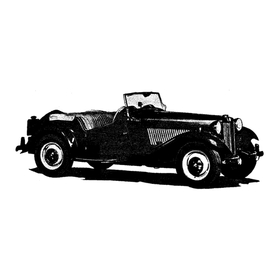
MG TF Series Workshop Manual (242 pages)
Brand:
MG
| Category:
Automobile
| Size: 27.73 MB
Table of Contents
Table of Contents
4
General Data
5
Gear Positions
9
The Instrument Panel
9
General Information (Series
9
Sidescreen Stowage
11
Folding the Hood
12
Jacking the Car
13
Warming up the Engine
13
Chassis and Engine Numbers
13
Engine Sectional View
14
Periodical Checks
16
Maintenance Attention
16
Frost Precautions
17
Sidescreen Stowage (Second Type)
18
General Data (Series TF)
20
Torque Spanner Date
23
The Engine
28
The Engine Components View and List
29
Engine General Description
31
The Lubrication System
31
Draining the Engine Sump
32
Removal and Replacement of the Engine Sump
33
Removal of the Oil Pump
34
Dismantling, Reassembling and Replacing the Oil Pump
34
Removal and Replacement of the Oil Pressure Relief Valve
35
Emergency Relief Valve
35
Removal and Replacement of the Main and Big-End Bearings
36
Removal and Replacement of the Rocker Assembly
37
Removal and Replacement of the Cylinder Head
37
Refitting the Cylinder Head
38
Removal and Replacement of the Piston Rings
39
Fitting the Gudgeon Pins
39
Dimantling and Reassembling Piston and Connecting Rod
39
Removal and Replacement of Pistons and Connecting Rods
39
Engine
39
Piston Sizes
40
Removal and Replacement of the Carburetors
41
Removal and Replacement of the Water Pump
41
Removal of the Timing Chain Case
41
Replacement of the Timing Chain Case
41
Removal of the Timing Chain
42
Replacement of the Timing Chain
42
Removal and Replacement of the Tappets
43
Removal and Replacement of the Camshaft
43
Removal of the Chain Tensioner
43
The Timing Chain Tensioner
43
Camshaft Bearings
44
Tappet Adjustment
44
Removing and Grinding the Valves
45
Grinding and Testing the Valves and Their Seatings
46
Removal and Replacement of Valve Guides
46
Removal and Replacement of Engine and Gearbox
47
Removal and Replacement of Flywheel
48
Removal and Replacment of Crankshaft
48
Internal Engine Components Diagram
49
Top Dead Centre Mark
51
Rear Main Bearing Oil Seal Cover
51
Oil Pressure
51
Regrinding the Crankshaft
51
The Engine Mounting and Control Link
52
Removing the Control Link
52
Refitting the Control Link
52
Locating Troubles
54
If Engine will Not Idle or Run Slowly
55
Excessive Oil Consumption
56
The Modified Oil Pump
58
Cylinder Head and Cylinder Block Modifications
58
Modified Oil Gauge Pipe Banjo
59
Modified Push-Rods and Adjusting Screws
59
The Modified Camshaft
59
The Fuel System
62
To Remove the Fuel Tank
62
Construction of the Fuel Pump
63
Action of the Fuel Pump
64
To Dismantle and Reassemble the Fuel Pump
64
Fuel System
64
Fuel Pump Adjustment
66
Tracing Fuel Pump Troubles
68
Failure to Deliver Fuel
69
Pump Noisy
69
Fuel Pump Maintenance
69
The Carburetters
70
Setting the Twin Carburetters
70
Carburetter Details
72
The Filter of the Carburetter
72
The Float Chamber
72
Centring the Jet
73
Sources of Caburetter Trouble
73
Water or Dirt in the Carburetter
73
Float-Chamber Flooding
73
Float Needle Sticking
74
The Carburetter Controls Diagram
75
The "TF" Carburetters
76
Removing the "TF" Fuel Tank
76
Late Type Fuel Pumps
76
The Ignition Equipment
77
Locating the Cause of Uneven Firing
78
Testing Low-Tension Circuit
78
High-Tension Cables
79
Attention to Sparking Plugs
79
Ignitjon Equipment C
79
Plug Inspection
80
Contact Breaker Mechanism
82
Removal of the Distributor
83
Distributor Lubrication
83
Ignition Timing Adjustment and Replacement of the Distributor
84
Dismantling the Distributor
85
The Condenser
85
Fitting New Distributor Bushes
85
Reassembling the Distributor
86
Replacement of Bearing Bushes
86
Distributor Components Diagram
87
Modified Distributor Fixing
88
Distributor with "High Lift" Cams
88
Draining and Filling the Cooling System
89
Cooling System Description
89
Cooling System (Series" to
89
To Remove the Radiator
90
Fan Belt Adjustment
90
The Water Pump - to Dismantle and Reassemble
90
The Fan and Water Pump Components Diagram
92
Cooling System ("TF" Series)
95
Cooling System (Series" TF ") DO
95
Cover Assembly
96
Release Bearing
96
Driven Plate Assembly
96
The Flywheel and Clutch
96
Flywheel and Clutch Adjustments
99
Running Adjustments
99
Removal of the Clutch
100
Dismantling the Clutch
100
Assembling the Clutch
100
Refitting the Clutch
101
Adjusting the Release Levers
101
Refacing the Driven Plate
102
Servicing the Clutch
102
Flywheel and Clutch E
102
Condition of Clutch Facing in Service
103
Spring Pressure
103
Driven Plates
103
Tolerances
103
Introduction of 8 In. Diameter Clutch
104
Introduction of a Clutch Control Rod
104
TD Series Gearbox and Clutch Diagram
105
The Gearbox
106
To Remove the Gearbox with the Engine in the Chassis
106
To Dismantle the Gearbox
106
To Dismantle the Mainshaft
108
Dismantling the Synchromesh Mechanism
108
The Gearbox Components Diagram
109
Reassembly of the Synchromesh Mechanism
111
Modified Synchromesh Hub
111
Speedometer Drive Modification
112
The Propeller Shaft
113
Attention to Universal Joints
113
Testing the Propeller Shaft for Wear
113
Removal of the Propeller Shaft
113
Dismantling the Propeller Shaft
114
To Examine and Check for Wear
114
Reassembling the Propeller Shaft
115
Replacement of the Propeller Shaft
116
The Rear Axle
117
The Rear Axle and Propeller Shaft Components Diagram
118
Removing and Replacing the Brake-Drum and Hub
120
Rear Axle Lubrication
120
Removal and Replacement of the Brake Plate Assembly
121
Removing and Replacing a Rear Axle Half-Shaft
122
Removing Rear Axle from Car
122
Important Points Concerning Axle Attention
123
Dismantling the Axle and Removing the Differential Assembly
124
Dismantling the Differential and Crown Wheel Assembly
124
Rear Axle Parts Examination
124
To Replace a Differential Cage
125
Assembling the Differential and Crown Wheel
126
Selecting an Axle Cover Spacer
126
To Replace a Pinion
127
To Fit a New Axle Casing
129
To Fit a New Axle Housing Cover
129
Replace Crown Wheel/Pinion Having Markings Different from the Original
129
Reassembling the Axle
130
Refitting the Rear Axle
130
Identification of "Unified" Screw Threads
132
The Rear Axle and Propeller Shaft Components (Series "TF") View
134
Dismantling and Reassembling the Springs
136
Removal and Replacement of the Rear Springs
136
The Rear Road Springs
136
Chassis, Suspension, Radiator, Fuel Tank, Exhaust System View
137
Maintenance of the Rear Springs
139
The Steering Gear Maintenance
140
The Steering Gear Components View
141
To Remove the Steering Wheel and Telescopic Extension
143
To Replace the Top and Bottom Steering Column Bushes
143
To Take out the Steering Column
143
Removal and Replacement of the Steering Gearbox
143
Dismantling the Steering Gearbox
144
Steering Ball Socket Assembly Threads
145
Steering Arm Ball Joints
145
Adjustment of the Rack Damper
145
Adjustment of the Inner Steering Ball Joint
145
Front Suspension
146
Checking and Adjusting Front Wheel Alignment
147
Checking the Wheel Camber, Castor Angle and Swivel Pin Angle
147
To Measure King-Pin Inclination
147
Removing the Front Suspension
148
Front Suspension Diagram
149
Hub Ball Bearings
150
Replacing the Front Suspension
150
Examination of Front Suspension Parts for Wear
150
To Dismantle the Swivel Pins
150
Reassembly of Swivel Pins
152
Removal and Replacement of the Brake-Drum and Hub
153
Replacement of the Front Hub
153
Removing and Replacing the Front Coil Spring
153
Fitting New Rubber Bushes to Lower Wishbone Inner Fulcrum
154
Grease Leakage from Front Hub
155
Modified Front Hub Grease Cap
155
The Hydraulic Dampers Maintenance
156
The Hydraulic Dampers Replenishing
156
Testing the Dampers
157
Removal of the Front Dampers
157
Removal and Replacement of Rear Hydraulic Dampers
157
Replacement of the Rear Damper Link Bearings (Girling)
158
To Dismantling the Links (Girling)
158
Fitting New Bearings to the Lever Arm and Lever Arm Link (Girling)
158
The Damper Settings
159
The Braking System
160
The Hydraulic System and Components Diagram
161
Braking System Maintenance
163
The Master Cylinder
163
Adjustment of the Brake Pedal
164
Brake-Shoe Adjustment
164
To Bleed the System (Expel Air)
165
Removal of the Master Cylinder
166
Assembling the Master Cylinder
166
Dismantling the Master Cylinder
166
Braking System
166
Replacing the Master Cylinder
167
Brake Assembly
167
Removal of the Wheel Cover
168
Dismantling the Wheel Cylinder
168
Assembling the Wheel Cylinder
168
Replacing of the Wheel Cylinder
168
The Hand Brake and Brake-Shoe Components Diagram
169
Rilining the Brake-Shoes
171
Removal of the Flexible Hose
171
Removal and Replacement of the Brake-Shoes
171
The Brake Fluid
172
The Hand Brake
172
Rear Brake Pipes
172
Braking Irregularities and Their Causes
172
Brakes Remain on
173
Unbalanced Braking
173
Brakes Grab
173
Electrical Equipment
174
Testing the Condition of the Battery
175
Battery Storage
175
Battery Maintenance
175
Preparation of Electrolyte
176
Duration and Rate of Initial Charge of the Battery
176
Battery Filling and Charging
176
The Dynamo
177
Removal and Replacement of the Dynamo
178
Dismantling the Dynamo
178
Servicing the Dynamo
179
Brushes
179
Commutator
179
Field Coils
179
Dynamo Reassembly
180
Armature
180
Bearings
180
The Starter
181
Removal and Replacement of Starter
181
The Starter Switch
182
The Starter Commutator and Brush Gear
182
The Starter Drive
182
Servicing the Starter
182
Starter Bearings
184
Starter Reassembly
184
How to Check and Adjust Electrical Setting
185
The Control Box
185
Regulator Adjustment
185
Cut-Out
186
Cleaning Contacts
186
Windscreen Wiper - Type CW
186
The Electric Horns
187
The Fuses
188
The Headlamps
189
Setting the Headlamps
189
Blown Fuses
189
Bulb Replacement
189
The Number-Plate Illumination Lamp
190
The Sidelamps
190
The Tail- and Stop-Lamps
190
The Panel Lamps
191
Removal of the Instrument Panel
191
The Ignition and Fuel Warning Lamps
191
Location and Remedy of Faults
191
The Charging Circuit
192
Battery in Low State of Charge
192
Battery Overcharged
192
The Lighting Circuits Troubles
193
The Starter Motor Troubles
193
Modified Dipping Switch
193
The Headlamp Beam Warning Light
193
Wiring Diagram
194
The "Correct-Acid-Level" Device
197
Modified Tail- and Stop-Lamps
197
The Headlamps (Tf)/The Light Units (TF)
198
Removing the Light Units (TF)
198
Replacing Headlamp Bulbs (TF)
198
Replacing the Light Units (TF)
198
The Tail-Lamps and Stop-Lights (TF)
199
Sidelamps
199
Cleaning the Lamps (TF)
199
Setting the Headlamps (TF)
199
Number-Plate Lamp (TF)
200
The Panel and Map Lights
200
Warning Lights (TF)
200
Replacement Bulbs (12 Volt) (TF)
200
Windscreen Wiper (TF)
201
Wiring Diagram for the Vehicle TF Series
202
Wheels and Tyres
203
Tyre Pressures
203
Spare Wheel
203
Road Wheels Removal and Replacement
203
Tyre Wear
204
The Valves
204
Tyre Removal
205
The Importance of Balance
205
Fitting the Tyres and Tubes
205
Repairing Tubes
206
Maintenance of Wire Wheels
207
Lubrication
208
Engine Lubrication
208
Mixing Lubricants
209
Extreme Cold Conditions
209
Recommended Lubricants
209
Gearbox Lubrication
210
Grease Run Lubrication Points
211
Carburetor Dashpot (Series "TD")
212
Steering Gearbox Lubrication
213
Air Cleaner Lubrication
213
Dynamo Lubrication
214
Front Wheel Bearings
214
Engine Oil Pick-Up
214
Priming the Engine Oil Pump
215
Special Tools
216
The Hood: Maintenance and Cleaning
225
Sidescreens
225
The Body
225
Cleaning Upholstery
226
Wings Removal and Replacement
226
The Running-Boards Removal and Replacement
226
The Body Removal and Replacement
226
Facia Board and Instrument Panel Removal and Replacement
228
Body Finish
228
Removing Front Wings (TF)
228
Removing Rear Wings (TF)
228
Removing and Replacing the Facia Board and Instrument Panel (TF)
229
Removing and Replacing the Body (TF)
229
Removing Running Boards (TF)
229
Chassis Frame Repairs
230
Checking Chassis Frame Alignment
230
Chassis Frame Straightening with Heat
231
Checking the Front Cross-Member
232
Straightening a Damaged Front End
232
Correcting a Twisted Frame
234
Fitting a New Front Cross-Member
236
Key to Recommended Lubricants
237
Lubrication (Series TD)
238
Lubrication Chart (Series TD)
239
Lubrication Chart (Series TF)
241
Advertisement
Advertisement
Related Products
MG TF
MG TD Series
MG Tissue Box
MG TR-EVO
MG 1967 Midget Mark III
MG 4 EV
MG 6
MG COMET EV 2023
MG Cyberster
MG F
MG Categories
I/O Systems
Control Unit
Transmitter
Automobile
Measuring Instruments
More MG Manuals
Login
Sign In
OR
Sign in with Facebook
Sign in with Google
Upload manual
Upload from disk
Upload from URL