Sign In
Upload
Manuals
Brands
Mellanox Technologies Manuals
Switch
Spectrum SN2700
Mellanox Technologies Spectrum SN2700 Manuals
Manuals and User Guides for Mellanox Technologies Spectrum SN2700. We have
7
Mellanox Technologies Spectrum SN2700 manuals available for free PDF download: Hardware User Manual, User Manual, Quick Installation Manual, Quick Reference Manual
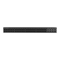
Mellanox Technologies Spectrum SN2700 Hardware User Manual (145 pages)
1U Switch Systems
Brand:
Mellanox Technologies
| Category:
Switch
| Size: 9.57 MB
Table of Contents
Table of Contents
3
Table 1: Revision History Table
10
Table 2: References
12
Chapter 1 Introduction to Mellanox SN2000 Spectrum™ Ethernet Switch Systems
14
Overview
14
Figure 1: SN2700 Front Side View
14
Figure 2: SN2740 Front Side View
15
Figure 3: SN2410 Front Side View
15
Figure 4: SN2100 Front Side View
15
Figure 5: SN2010 Front Side View
15
Figure 6: SN2700 and SN2410 Rear Side View
15
Figure 7: SN2740 Rear Side View
15
Figure 8: SN2100 Rear Side View
15
Speed and Switching
16
Management Interfaces, Psus and Fans
16
Table 3: Speed and Switching Capabilities
16
Table 4: Management Interfaces, Psus and Fans
16
Figure 9: SN2010 Rear Side View
16
Features
17
Certifications
17
Ordering Information
18
Table 5: Ordering Part Numbers (Opns)
18
Chapter 2 Installation
22
Safety Warnings
22
System Installation and Initialization
23
Air Flow
23
Table 6: Air Flow Color Legend
24
Figure 10: Air Flow Direction Marking - Power Side Inlet to Connector Side Outlet
24
Package Contents
25
19" Systems Mounting Options
25
Figure 11: Air Flow Direction Marking - Connector Side Inlet to Power Side Outlet
25
Static Rail Kit for SN2700
26
Table 7: Installation Kit
26
Figure 12: Rack Rail Kit Parts
26
Figure 13: Installation Options
28
Figure 14: Attaching the Rails to the Chassis
29
Figure 15: Attaching the Brackets to the Chassis
29
Figure 16: Installing the Cage Nuts
30
Figure 17: Attaching the Brackets to the Rack
30
Telescopic Rail Kit for SN2700
31
Figure 18: Sliding the Blades in the Rails
31
Table 8: Installation Kit
32
Figure 19: Rack Rail Kit Parts
33
Figure 20: Rails Separation
34
Figure 21: Installing the Cage Nuts
34
Figure 22: Mounting the Outer Rails into the Rack
35
Figure 23: Attaching the Inner Rails to the Switch
35
Figure 24: Securing the Chassis in the Inner Rails
35
Figure 25: Sliding the Switch into the Rack
36
Figure 26: Pulling the Unit Outwards
37
Figure 27: Locking Mechanism
37
Static Rail Kit for SN2740 and SN2410
38
Table 9: Installation Kit
38
Figure 28: Rack Rail Kit Parts
39
Figure 29: Installation Options
40
Figure 30: Attaching the Rails to the Chassis
40
Figure 31: Installing the Cage Nuts
41
Figure 32: Attaching the Rails to the Rack
41
Side by Side Mounting for SN2100/SN2010 Rail Kit
42
Figure 33: Sliding the Blades in the Rails
42
Table 10: Installation Kit
43
Figure 34: Rack Rail Kit Parts
44
Figure 35: Coupling the Cables with Cable-Ties
45
Figure 36: Coupled Cables - Rear View
45
Figure 37: Cables Within the Rail
46
Figure 38: Attach the Blades to the System
47
Figure 39: Attached Rail with Threaded Cables - Top View
47
Figure 40: Sliding the Frame Sliders into the Rails
48
Figure 41: Installing the Cage Nuts
48
Figure 42: Attaching the Frame to the Rack
49
Figure 43: Sliding the System's Blades in the Rails
49
Cable Installation
50
Figure 44: SN2700, SN2100 and SN2010 QSFP Cable Orientation
50
Splitter (Breakout) Cables and Adapters
51
Figure 45: SN2010 SFP Cable Orientation
51
Figure 46: SN2740 Cable Orientation
51
Figure 47: SN2410 Cable Orientation
51
Figure 48: Splitter (Breakout or Fanout) Cables
52
Figure 49: SN2700 and SN2740 Splitting Options
53
Figure 50: SN2410 Splitting Options
53
Initial Power on
54
Figure 51: SN2100 Splitting Options
54
Figure 52: System Status Leds 5 Minutes after Power on in SN2700
55
Figure 53: System Status Leds 5 Minutes after Power on in SN2740
55
Figure 54: System Status Leds 5 Minutes after Power on in SN 2410
55
System Bring-Up
56
Figure 55: System Status Leds 5 Minutes after Power on in SN2100
56
Figure 56: System Status Leds 5 Minutes after Power on in SN2010
56
Figure 57: Two Power Inlets - Electric Caution Notifications
56
Configuring Network Attributes Using Onyx (MLNX-OS)
57
Table 11: Serial Terminal Program Configuration
57
Table 12: Configuration Wizard Session
57
Table 13: Configuration Wizard Session - Static IP Configuration
59
Configuring Network Attributes Using Cumulus Linux
61
FRU Replacements
62
Power Supply
62
Fans
63
Figure 58: PS Unit Pulled out
63
Figure 59: Fan Module Latches
64
Chapter 3 Interfaces
65
Supported Interfaces
65
Data Interfaces
65
Table 14: High Power/Lr4 Transceivers Support
65
Speed
66
Figure 60: Using 4.5W Modules on Ports 49, 50, 55, 56 in SN2410
66
Figure 61: Supported 25Gbe and 40/100Gbe Cables on IPL Ports (SN2010 to SN2010 Connection)
66
RS232 (Console)
67
Management
67
Usb
67
Reset Button
68
Status and Port Leds
68
Leds
68
LED Notifications
68
Table 15: Leds Symbols
68
Figure 62: System Status Leds - Front and Rear Sides in SN2700
69
Figure 63: System Status Leds - Front Side in SN2740
69
Figure 64: System Status Leds - Front and Rear Sides in SN2410
70
Figure 65: System Status LED in SN2100
70
Figure 66: System Status LED in SN2010
70
Table 16: System Status LED Assignments
71
Figure 67: Fan Status LED in SN2700 - Front and Rear Sides
71
Figure 68: System Status Leds - Front Side in SN2740
71
Table 17: Fan Status Front LED Assignments
72
Figure 69: Fan Status LED in SN2410 - Front and Rear Sides
72
Figure 70: Fan Status LED in SN2100
72
Figure 71: Fan Status LED in SN2010
72
Table 18: Fan Status Rear LED Assignments (One LED Per Fan)
73
Figure 72: Power Status LED
73
Table 20: Power Supply Unit Status Front LED Assignments for SN2100/SN2010
74
Figure 73: SN2700 and SN2410 Rear Side Panel
74
Figure 74: SN2740 Side Panel
74
Table 21: Power Supply Unit Status Rear LED Assignments
75
Table 22: Bad Port LED Assignments
76
Figure 75: SN2740 Port Leds
76
Figure 76: SN2410 SFP28 Port Leds
76
Figure 77: SN2410 QSFP28 Port Leds
76
Figure 78: SN2010 QSFP Port Leds
76
Figure 79: Sn201Port Leds
77
Figure 80: SN2100 Port Leds
77
Inventory Information
78
Table 23: Port Leds in Ethernet System Mode
78
Figure 81: SN2700 Pull-Out Tab
78
Figure 82: SN2740 Inventory Information Illustration
79
Figure 83: SN2410 Inventory Information Illustration
80
Figure 84: SN2100 Pull-Out Tab
80
Figure 85: SN2010 Pull-Out Tab
81
Chapter 4 Software Management
82
Upgrading Software
82
Onyx (MLNX-OS) Software Upgrade
82
Switch Firmware Update
82
Cumulus Linux Software Upgrade
82
Chapter 5 Troubleshooting
83
Troubleshooting Instructions
83
Table 24: Troubleshooting
83
Chapter 6 Specifications
85
SN2700 Series
85
Table 25: SN2700 Specifications
85
SN2740 Series
86
Table 26: SN2740 Specifications
86
SN2410 Series
87
Table 27: SN2410 Specifications
87
SN2100 Series
88
Table 28: SN2100 Specifications
88
SN2010 Series
89
Table 29: SN2010 Specifications
89
Table 30: Opns for Replacement Parts
90
Table 31: QSFP Pin Description 1-20
92
Table 32: QSFP Pin Description 21-38
93
Figure 86: Rear View of Module with Pin Placement
94
Figure 87: RJ45 to DB9 Harness Pinout
96
Advertisement
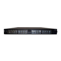
Mellanox Technologies Spectrum SN2700 Hardware User Manual (130 pages)
1U Switch Systems
Brand:
Mellanox Technologies
| Category:
Switch
| Size: 8.5 MB
Table of Contents
Table of Contents
3
Table 1: Revision History Table
9
About this Manual
10
Intended Audience
10
Table 2: References
10
Chapter 1 Introduction to Mellanox SN2000 Spectrum™ Ethernet Switch Systems
12
Overview
12
Figure 1: SN2700 Front Side View
12
Figure 2: SN2740 Front Side View
13
Figure 3: SN2410 Front Side View
13
Figure 4: SN2100 Front Side View
13
Figure 5: SN2700 and SN2410 Rear Side View
13
Figure 6: SN2740 Rear Side View
13
Figure 7: SN2100 Rear Side View
13
Speed and Switching
14
Management Interfaces, Psus and Fans
14
Features
14
Certifications
14
Table 3: Speed and Switching Capabilities
14
Table 4: Management Interfaces, Psus and Fans
14
Ordering Information
15
Table 5: Ordering Part Numbers (Opns)
15
Chapter 2 Installation
19
Safety Warnings
19
System Installation and Initialization
20
Air Flow
20
Package Contents
21
Table 6: Air Flow Color Legend
21
Figure 8: Air Flow Direction Marking - Power Side Inlet to Connector Side Outlet
21
Figure 9: Air Flow Direction Marking - Connector Side Inlet to Power Side Outlet
21
19" Systems Mounting Options
22
Static Rail Kit for SN2700
22
Table 7: Installation Kit
22
Figure 10: Rack Rail Kit Parts
23
Figure 11: Installation Options
24
Figure 12: Attaching the Rails to the Chassis
25
Figure 13: Attaching the Brackets to the Chassis
25
Figure 14: Installing the Cage Nuts
26
Figure 15: Attaching the Brackets to the Rack
26
Telescopic Rail Kit for SN2700
27
Figure 16: Sliding the Blades in the Rails
27
Table 8: Installation Kit
28
Figure 17: Rack Rail Kit Parts
29
Figure 18: Rails Separation
30
Figure 19: Installing the Cage Nuts
30
Figure 20: Mounting the Outer Rails into the Rack
31
Figure 21: Attaching the Inner Rails to the Chassis
31
Figure 22: Securing the Chassis in the Inner Rails
31
Figure 23: Sliding the Switch into the Rack
32
Figure 24: Pulling the Unit Outwards
33
Figure 25: Locking Mechanism
33
Static Rail Kit for SN2740 and SN2410
34
Table 9: Installation Kit
34
Figure 26: Rack Rail Kit Parts
35
Figure 27: Installation Options
36
Figure 28: Attaching the Rails to the Chassis
36
Figure 29: Installing the Cage Nuts
37
Figure 30: Attaching the Rails to the Rack
37
Side by Side Mounting for SN2100 Rail Kit
38
Table 10: Installation Kit
38
Figure 31: Sliding the Blades in the Rails
38
Figure 32: Rack Rail Kit Parts
40
Figure 33: Coupling the Cables with Cable-Ties
41
Figure 34: Coupled Cables - Rear View
41
Figure 35: Cables Within the Rail
42
Figure 36: Attach the Blades to the System
42
Figure 37: Attached Rail with Threaded Cables - Top View
43
Figure 38: Sliding the Frame Sliders into the Rails
43
Figure 39: Installing the Cage Nuts
44
Figure 40: Attaching the Frame to the Rack
44
Figure 41: Sliding the System's Blades in the Rails
45
Cable Installation
46
Figure 42: SN2700 and SN2100 Cable Orientation
46
Breakout Cables and Adapters
47
Figure 43: SN2740 Cable Orientation
47
Figure 44: SN2410 Cable Orientation
47
Figure 45: Breakout or Fanout Cables
48
Figure 46: SN2700 and S740 Splitting Options
48
Initial Power on
49
Figure 47: SN2410 Splitting Options
49
Figure 48: SN2100 Splitting Options
49
Figure 49: System Status Leds 5 Minutes after Power on in SN2700
50
Figure 50: System Status Leds 5 Minutes after Power on in SN2740
50
Figure 51: System Status Leds 5 Minutes after Power on in SN 2410
50
System Bring-Up
51
Configuring Network Attributes Using MLNX-OS
51
Figure 52: System Status Leds 5 Minutes after Power on in SN 2100
51
Figure 53: Two Power Inlets - Electric Caution Notifications
51
Table 11: Serial Terminal Program Configuration
52
Table 12: Configuration Wizard Session
52
Table 13: Configuration Wizard Session - Static IP Configuration
54
Configuring Network Attributes Using Cumulus Linux
56
FRU Replacements
57
Power Supply
57
Fans
58
Figure 54: PS Unit Pulled out
58
Figure 55: Fan Module Latches
59
Chapter 3 Interfaces
60
Supported Interfaces
60
Data Interfaces
60
Table 14: High Power/Lr4 Transceivers Support
60
Figure 56: Using 4.5W Modules on Ports 49, 50, 55, 56 in SN2410
60
Speed
61
RS232 (Console)
61
Management
61
Usb
61
Reset Button
62
Status and Port Leds
62
Leds
62
LED Notifications
62
Table 15: Leds Symbols
62
Figure 57: System Status Leds - Front and Rear Sides in SN2700
63
Figure 58: System Status Leds - Front Side in SN2740
63
System Status Led
63
Table 16: System Status LED Assignments
64
Figure 59: System Status Leds - Front and Rear Sides in SN2410
64
Figure 60: System Status LED in SN2100
64
Figure 61: Fan Status LED in SN2700 - Front and Rear Sides
65
Figure 62: System Status Leds - Front Side in SN2740
65
Figure 63: Fan Status LED in SN2410 - Front and Rear Sides
65
Table 17: Fan Status Front LED Assignments
66
Table 18: Fan Status Rear LED Assignments (One LED Per Fan)
66
Figure 64: Fan Status LED in SN2100
66
Figure 65: Power Status LED
67
Figure 66: SN2700 and SN2410 Rear Side Panel
67
Figure 67: SN2740 Side Panel
67
Table 20: Power Supply Unit Status Front LED Assignments for SN2100
68
Table 21: Power Supply Unit Status Rear LED Assignments
68
Table 22: Bad Port LED Assignments
69
Figure 68: SN2700 Port Leds
69
Figure 69: SN2740 Port Leds
70
Figure 70: SN2410 SFP28 Port Leds
70
Figure 71: SN2410 QSFP28 Port Leds
70
Figure 72: SN2100 Port Leds
70
Inventory Information
71
Table 23: Port Leds in Ethernet System Mode
71
Figure 73: SN2700 Pull-Out Tab
71
Figure 74: SN2740 Inventory Information Illustration
72
Figure 75: SN2410 Inventory Information Illustration
73
Figure 76: SN2100 Pull-Out Tab
73
Chapter 4 Software Management
74
Upgrading Software
74
MLNX-OS Software Upgrade
74
Switch Firmware Update
74
Cumulus Linux Software Upgrade
74
Chapter 5 Troubleshooting
75
Troubleshooting Instructions
75
Table 24: Troubleshooting
75
Chapter 6 Specifications
77
SN2700 Series
77
Table 25: SN2700 Specifications
77
SN2740 Series
78
Table 26: SN2740 Specifications
78
SN2410 Series
79
Table 27: SN2410 Specifications
79
SN2100 Series
80
Table 28: SN2100 Specifications
80
Table 29: Opns for Replacement Parts
81
Table 30: QSFP Interface Pins 1-23
83
Table 31: QSFP Interface Pins 24-38
84
Figure 77: Rear View of Module with Pin Placement
85
Figure 78: RJ45 to DB9 Harness Pinout
87
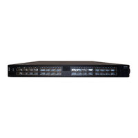
Mellanox Technologies Spectrum SN2700 Hardware User Manual (120 pages)
1U Switch Systems
Brand:
Mellanox Technologies
| Category:
Switch
| Size: 7.79 MB
Table of Contents
Table of Contents
3
About this Manual
9
Intended Audience
9
Chapter 1 Introduction to Mellanox SN2000 Spectrum™ Ethernet Switch Systems
11
Overview
11
Speed and Switching
12
Figure 1: SN2700 Front Side View
12
Figure 2: SN2410 Front Side View
12
Figure 3: SN2100 Front Side View
12
Figure 4: SN2700 and SN2410 Rear Side View
12
Figure 5: SN2100 Rear Side View
12
Management Interfaces, Psus and Fans
13
Features
13
Certifications
13
Ordering Information
14
Safety Warnings
17
System Installation and Initialization
17
Chapter 2 Installation
17
Air Flow
18
Package Contents
19
Figure 6: Air Flow Direction Marking - Power Side Inlet to Connector Side Outlet
19
Figure 7: Air Flow Direction Marking - Connector Side Inlet to Power Side Outlet
19
19" Systems Mounting Options
20
Static Rail Kit for SN2700
20
Figure 8: Rack Rail Kit Parts
21
Figure 9: Installation Options
22
Figure 10: Attaching the Rails to the Chassis
22
Figure 11: Attaching the Brackets to the Chassis
23
Figure 12: Installing the Cage Nuts
23
Figure 13: Attaching the Brackets to the Rack
24
Figure 14: Sliding the Blades in the Rails
24
Telescopic Rail Kit for SN2700
25
Figure 15: Rack Rail Kit Parts
26
Figure 16: Rails Separation
26
Figure 17: Installing the Cage Nuts
27
Figure 18: Mounting the Outer Rails into the Rack
27
Figure 19: Attaching the Inner Rails to the Chassis
28
Figure 20: Securing the Chassis in the Inner Rails
28
Figure 21: Sliding the Switch into the Rack
29
Figure 22: Pulling the Unit Outwards
29
Static Rail Kit for SN2410
30
Figure 23: Locking Mechanism
30
Figure 24: Rack Rail Kit Parts
31
Figure 25: Installation Options
32
Figure 26: Attaching the Rails to the Chassis
32
Figure 27: Installing the Cage Nuts
33
Figure 28: Attaching the Rails to the Rack
33
Figure 29: Sliding the Blades in the Rails
33
Side by Side Mounting for SN2100 Rail Kit
34
Figure 30: Rack Rail Kit Parts
35
Figure 31: Coupling the Cables with Cable-Ties
36
Figure 32: Coupled Cables - Rear View
36
Figure 33: Cables Within the Rail
36
Figure 34: Attach the Blades to the System
37
Figure 35: Attached Rail with Threaded Cables - Top View
37
Figure 36: Sliding the Frame Sliders into the Rails
38
Figure 37: Installing the Cage Nuts
38
Figure 38: Attaching the Frame to the Rack
39
Figure 39: Sliding the System's Blades in the Rails
39
Cable Installation
40
Figure 40: SN2700 and SN2100 Cable Orientation
40
Breakout Cables and Adapters
41
Figure 41: SN2410 Cable Orientation
41
Figure 42: Breakout or Fanout Cables
42
Figure 43: SN2700 Splitting Options
42
Initial Power on
43
Figure 44: SN2410 Splitting Options
43
Figure 45: SN2100 Splitting Options
43
Figure 46: System Status Leds 5 Minutes after Power on in SN2700
44
Figure 47: System Status Leds 5 Minutes after Power on in SN 2410
44
Figure 48: System Status Leds 5 Minutes after Power on in SN 2100
44
System Bring-Up
45
Configuring Network Attributes Using MLNX-OS
45
Figure 49: Two Power Inlets - Electric Caution Notifications
45
Table 11: Serial Terminal Program Configuration
46
Table 13: Configuration Wizard Session - Static IP Configuration
47
Configuring Network Attributes Using Cumulus Linux
49
FRU Replacements
50
Power Supply
50
Fans
51
Figure 50: PS Unit Pulled out
51
Figure 51: Fan Module Latches
52
Chapter 3 Interfaces
53
Supported Interfaces
53
Data Interfaces
53
Speed
53
RS232 (Console)
53
Management
53
Usb
54
Reset Button
54
Status and Port Leds
55
Leds
55
LED Notifications
55
Figure 52: System Status Leds - Front and Rear Sides in SN2700
56
Figure 53: System Status Leds - Front and Rear Sides in SN2410
56
Figure 54: System Status LED in SN2100
56
Leds
56
Figure 55: Fan Status LED in SN2700 - Front and Rear Sides
57
Figure 56: Fan Status LED in SN2410 - Front and Rear Sides
57
Figure 57: Fan Status LED in SN2100
58
Figure 58: Power Status LED
59
Figure 59: SN2700 and SN2410 Rear Side Panel
59
Bad Port Led
60
Figure 60: SN2700 Port Leds
62
Figure 61: SN2410 SFP28 Port Leds
62
Figure 62: SN2410 QSFP28 Port Leds
62
Figure 63: SN2100 Port Leds
62
Inventory Information
63
Figure 64: SN2700 Pull-Out Tab
63
Figure 65: SN2410 Inventory Information Illustration
64
Figure 66: SN2100 Pull-Out Tab
64
Chapter 4 Software Management
65
Upgrading Software
65
MLNX-OS Software Upgrade
65
Switch Firmware Update
65
Cumulus Linux Software Upgrade
65
Chapter 5 Troubleshooting
66
Troubleshooting Instructions
66
Chapter 6 Specifications
68
SN2700 Series
68
SN2410 Series
69
SN2100 Series
70
Figure 67: QSFP28 Connector Male and Female Views
74
Figure 68: Rear View of Module with Pin Placement
75
Figure 69: RJ45 to DB9 Harness Pinout
77
Advertisement
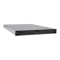
Mellanox Technologies Spectrum SN2700 Hardware User Manual (109 pages)
1U Switch Systems
Brand:
Mellanox Technologies
| Category:
Switch
| Size: 3.78 MB
Table of Contents
Table of Contents
3
Revision History
8
Table 1: Revision History Table
8
About this Manual
9
Chapter 1 Introduction to Mellanox SN2XXX Spectrum
11
Ethernet Switch Systems
11
Overview
11
Speed and Switching
12
Management Interfaces and Frus
12
Figure 1: SN2700 Front Side View
12
Figure 2: SN2410 Front Side View
12
Figure 3: SN2700 and SN2410 Rear Side View
12
Table 3: Speed and Switching Capabilities
12
Table 4: Management Interfaces and Frus
12
Features
13
Certifications
13
Ordering Information
13
Table 5: Ordering Part Numbers (Opns)
13
Chapter 2 Installation
15
Safety Warnings
15
Air Flow
16
Table 6: Air Flow Color Legend
16
Package Contents
17
Figure 4: Air Flow Direction Marking - Power Side Inlet to Connector Side Outlet
17
Figure 5: Air Flow Direction Marking - Connector Side Inlet to Power Side Outlet
17
Mounting Options
18
19" Systems Mounting - Static Rail-Kit for SN2700
18
Table 7: Installation Kit
18
Figure 6: Rack Rail Kit Parts
19
Figure 7: Installation Options
20
Figure 8: Attaching the Rails to the Chassis
20
Figure 9: Attaching the Brackets to the Chassis
21
Figure 10: Installing the Cage Nuts
21
Figure 11: Attaching the Brackets to the Rack
22
Figure 12: Sliding the Blades in the Rails
22
19" Systems Mounting- Telescopic Rail-Kit for SN2700
23
Table 8: Installation Kit
23
Figure 13: Rack Rail Kit Parts
24
Figure 14: Rails Separation
24
Figure 15: Installing the Cage Nuts
25
Figure 16: Mounting the Outer Rails into the Rack
25
Figure 17: Attaching the Inner Rails to the Chassis
26
Figure 18: Securing the Chassis in the Inner Rails
26
Figure 19: Sliding the Switch into the Rack
27
Figure 20: Pulling the Unit Outwards
27
19" Systems Mounting - Static Rail-Kit for SN2410
28
Figure 21: Locking Mechanism
28
Table 9: Installation Kit
28
Figure 22: Rack Rail Kit Parts
29
Figure 23: Installation Options
30
Figure 24: Attaching the Rails to the Chassis
30
Figure 25: Installing the Cage Nuts
31
Figure 26: Attaching the Rails to the Rack
31
Figure 27: Sliding the Blades in the Rails
31
Cable Installation
32
Breakout Cables and Adapters
32
Figure 28: Cable Orientation
32
Figure 29: Breakout or Fanout Cables
33
Figure 30: SN2700 Splitting Options
33
Initial Power on
34
Figure 31: SN2410 Splitting Options
34
System Bring-Up
35
Configuring Network Attributes Using MLNX-OS
35
Figure 32: System Status Leds 5 Minutes after Power on
35
Figure 33: Two Power Inlets - Electric Caution Notifications
35
Table 10: Serial Terminal Program Configuration
36
Table 11: Configuration Wizard Session
37
Table 12: Configuration Wizard Session - Static IP Configuration
38
Configuring Network Attributes Using Cumulus Linux
40
FRU Replacements
40
Power Supply
40
Fans
41
Figure 34: PS Unit Pulled out
41
Figure 35: Fan Module Latches
42
Chapter 3 Software Management
43
Upgrading Software
43
MLNX-OS Software Upgrade
43
Cumulus Linux Software Upgrade
43
Chapter 4 Interfaces
44
Supported Interfaces
44
Data Interfaces
44
Speed
44
RS232 (Console)
44
Management
44
Usb
45
Reset Button
45
Leds
46
LED Notifications
46
Table 13: Leds Symbols
46
Table 14: System Status LED Assignments
47
Table 15: Fan Status Front LED Assignments
48
Table 16: Fan Status Rear LED Assignments (One LED Per Fan)
48
Table 17: Power Supply Unit Status Front LED Assignments
49
Table 18: Power Supply Unit Status Rear LED Assignments
49
Table 19: Bad Port LED Assignments
50
Table 20: Port Leds in Ethernet System Mode
51
Inventory Information
52
Chapter 5 Troubleshooting
54
Troubleshooting Instructions
54
Table 21: Troubleshooting
54
Chapter 6 Specifications
56
SN2700 Series
56
Table 22: SN2700 Specifications
56
SN2410 Series
58
Table 23: SN2410 Specifications
58
Appendix A Accessory and Replacement Parts
59
Table 24: Opns for Replacement Parts
59
Appendix B Thermal Threshold Definitions
60
Appendix C Interface Specifications
61
QSFP Interface
61
SFP+ Interface
63
C.2 SFP+ Interface
63
C.3 RJ45 to DB9 Harness Pinout
65
Appendix D Disassembly and Disposal
66
Disassembly Procedure
66
Appendix E Safety Warnings (Multiple Languages)
67
Nordic Countries Notices
67
Installation Safety Warnings (English)
67
( אזהרות בטיחות בהתקנהHebrew)
70
E.3 ( אזהרות בטיחות בהתקנהHebrew)
70
安裝安全性警告 (Chinese)
74
Avertissements de Sécurité Pour L'installation (French)
79
Installation Sicherheitshinweise(German)
82
E.6 Installation Sicherheitshinweise(German)
82
Advertencias de Seguridad de Instalación (Spanish)
86
Предупреждения По Технике Безопасности При Установке (Russian)
90
Avertismente Privind Siguranţa la Instalare (Romanian)
93
Sigurnosna Upozorenja Za Instaliranje (Croatian)
97
Avvertenze DI Sicurezza Per L'installazione (Italian)
101
Montaj Güvenlik Uyarıları (Turkish)
105
E.13 Japan VCCI Statement
109
Mellanox Technologies Spectrum SN2700 User Manual (76 pages)
10/25/40/50/100GbE Open Ethernet 1U Switch Systems
Brand:
Mellanox Technologies
| Category:
Switch
| Size: 13.27 MB
Table of Contents
Table of Contents
3
1 Ordering Information
7
SN2700 Ordering Part Numbers
7
SN2410 Ordering Part Numbers
7
SN2100 Ordering Part Numbers
8
SN2010 Ordering Part Numbers
9
2 Introduction
10
Speed and Switching Capabilities
11
Management Interfaces, Psus and Fans
12
Features
12
Certifications
12
3 Installation
13
System Installation and Initialization
13
Safety Warnings
13
Air Flow
16
Package Contents
17
19" System Mounting Options
17
SN2700 Static Rail Kit
17
Removing the System from the Rack
21
SN2700 Telescopic Rail Kit
21
Removing the System from the Rack
24
SN2740/SN2410 Static Rail Kit
25
SN2100/SN2010 Side by Side Mounting Rail Kit
27
SN2100/SN2010 Static Single Switch Rail Kit
31
Cable Installation
33
Splitter (Breakout) Cables and Adapters
35
Using Splitter (Breakout) Cables with Mellanox Onyx (MLNX-OS)
35
Using Splitter (Breakout) Cables with Cumulus Linux
35
SN2700 and SN2740 Splitting Options
35
SN2410 Splitting Options
36
SN2100 Splitting Options
36
SN2010 Splitting Options
36
Initial Power on
37
System Bring-Up
38
Configuring Network Attributes Using Mellanox Onyx (MLNX-OS)
38
Manual Host Configuration
38
Disable Dynamic Host Configuration Protocol (DHCP)
41
Remote Connection with Mellanox Onyx (MLNX-OS)
42
Configuring Network Attributes Using Cumulus Linux
42
Remote Connection with Cumulus Linux
42
FRU Replacements
42
Power Supply
42
Fans
43
4 Interfaces
45
Data Interfaces
45
Supported Passive Cables in Sn2010Bm
46
Speed
46
RS232 (Console)
46
Management
46
Usb
47
Reset Button
47
Status and Port Leds
47
LED Notifications
47
System Status LED
48
Fan Status LED
50
Power Supply Status Leds
51
Unit Identification LED
53
Bad Port LED
53
Port Leds
54
Inventory Information
55
5 Software Management
57
Upgrading Software
57
Mellanox Onyx (MLNX-OS) Software Upgrade
57
Switch Firmware Update
57
Cumulus Linux Software Upgrade
57
6 Troubleshooting
58
7 Specifications
60
SN2700 Series
60
SN2740 Series
61
SN2410 Series
62
SN2100 Series
64
SN2010 Series
65
8 Appendixes
67
Accessory and Replacement Parts
67
Thermal Threshold Definitions
68
Interface Specifications
68
QSFP28 Pin Description
68
SFP28 Pin Description
71
RJ45 to DB9 Harness Pinout
72
RJ45 to RJ45 Harness
73
Disassembly and Disposal
73
Disassembly Procedure
73
Disposal
74
9 Document Revision History
75
Mellanox Technologies Spectrum SN2700 Quick Installation Manual (8 pages)
1U Switch Systems
Brand:
Mellanox Technologies
| Category:
Switch
| Size: 1.8 MB
Mellanox Technologies Spectrum SN2700 Quick Reference Manual (2 pages)
SX Series; SN Series
Brand:
Mellanox Technologies
| Category:
Network Router
| Size: 0.4 MB
Advertisement
Related Products
Mellanox Technologies Spectrum SN2410
Mellanox Technologies Spectrum SN2100
Mellanox Technologies Spectrum SN2740
Mellanox Technologies Spectrum SN2010
Mellanox Technologies SwitchX-2 MSX1012B-1BFS
Mellanox Technologies SX6518-6R
Mellanox Technologies SB7800
Mellanox Technologies Switch-IB
Mellanox Technologies SX6710G
Mellanox Technologies SX6790
Mellanox Technologies Categories
Switch
Computer Hardware
Adapter
Network Card
Network Router
More Mellanox Technologies Manuals
Login
Sign In
OR
Sign in with Facebook
Sign in with Google
Upload manual
Upload from disk
Upload from URL