Sign In
Upload
Manuals
Brands
Megger Manuals
Test Equipment
BITE 2
Megger BITE 2 Manuals
Manuals and User Guides for Megger BITE 2. We have
2
Megger BITE 2 manuals available for free PDF download: Instruction Manual
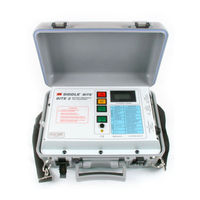
Megger BITE 2 Instruction Manual (135 pages)
Battery Impedance Test Equipment
Brand:
Megger
| Category:
Test Equipment
| Size: 1.94 MB
Table of Contents
Table of Contents
4
Introduction
7
About the BITE 2 and BITE 2P
7
How the BITE 2/2P Works
8
Applications for the BITE 2/2P
9
BITE 2/2P Measurements
10
Upon Receipt of the BITE 2/2P
10
Figure 1-1: BITE 2 Instrument
11
Safety First
12
Figure 1-2: BITE 2P Instrument
12
How to Use this Manual
13
Typographic Conventions
13
Safety
14
Overview
14
Safety Requirements
14
Connection to Power Source
16
Fuse Replacement
16
Cautions and Warnings
16
Controls, Connectors, Indicators and Menus
17
Overview
17
BITE 2 Transmitter
18
Figure 3-1: BITE 2 Transmitter
18
BITE 2P Transmitter
20
Figure 3-2: BITE 2P Transmitter
20
Figure 3-3: Voltage Selector Card Orientation
21
Receiver
22
Figure 3-4: Receiver Controls, Connectors, and Indicators
22
Receiver Keys
23
Figure 3-5: Flowchart for Receiver Menus
24
Figure 3-6: Flowchart for Receiver Menus
25
Figure 3-7: Flowchart for Receiver Menus
26
Figure 3-8: Receiver Menu
27
Receiver Reset Switch
28
Figure 3-9: Receiver RESET Switch
28
Standard Test Procedure
29
Overview
29
Step One: Prepare for Testing
31
Step Two: Powering-On the Receiver
32
Figure 4-1: Receiver Controls, Connectors and Indicators
32
Step Three: Scanning Test Information with the Wand (Optional)
34
If You Do Not Want to Scan Information Using the Wand
34
If You Want to Scan Information Using the Wand
34
Figure 4-3: Scanning Test Information
35
Step Four: Setting Baseline, Warning and Fail Values
36
Step Five: Splitting the Strap (if Needed)
37
If You Do Not Want to Split the Strap
37
If You Want to Split the Strap
37
Step Six: Connecting the Receiver and the BITE 2 or BITE 2P Transmitter to the Battery
39
Figure 4-4: Receiver Controls, Connectors, and Indicators
39
Figure 4-5: BITE 2/2P Transmitter Connected to the Battery
40
Connecting the BITE 2 or BITE 2P Transmitter
41
Step Seven: Measuring the Cell and the Strap
42
Figure 4-6: Receiver and Potential Probe Positioned on Top of Battery Cell Terminals
43
Figure 4-7: Receiver and Potential Probe Positioned on Top of Battery Strap Terminals
44
Measuring the Next Section of a Sectioned Battery String
46
Step Eight: What to Do When the Test Is Complete
47
Reviewing a Test
47
Retesting Cells and Straps
48
Printing an Active Test to Review the Data (BITE 2P)
48
Powering down and Disconnecting the BITE 2/2P
49
Modified Procedures for Special Conditions
51
Overview
51
Reversing the Current Source Leads
51
Verifying the Source Current
52
Figure 5-1: Reversing the Current Source Leads on a Single String of Cells When a High
52
Sectioning a Battery System
53
Figure 5-3: Sectioning a Parallel String of Cells
56
Transferring, Printing, and Deleting Test Results
58
Overview
58
Exporting Test Results from the Receiver to a PC
59
Figure 6-1: Exporting Data to a PC
60
Printing Test Results in the BITE 2P Transmitter Printer
61
Figure 6-2: Printing Test Results
61
Deleting Test Results from the Receiver
62
Figure 6-3: Deleting Test Results from the Receiver
63
Interpreting Test Results
64
Overview
64
Instantaneous Interpretation
65
Short-Term Interpretation
66
Long-Term Interpretation
66
Temperature Corrections
67
Figure 7-1: Generic Curve of Impedance Vs. Cell Life
67
Setting Options
69
Overview
69
Turning the Receiver Backlight on and off
70
Adjusting the Receiver Screen Contrast
70
Selecting the Receiver Language
71
Setting the Receiver Clock
71
Selecting the Line Frequency
73
Maintenance and Troubleshooting
74
Overview
74
Cleaning and Inspecting the BITE 2 and BITE 2P
75
Charging the Receiver
75
Replacing Batteries in the Receiver
76
Figure 9-1: RTC Battery "Piggybacks" the System Battery
78
Maintaining the Receiver Charger in the BITE 2 and BITE 2P
79
Maintaining Fuses in the BITE 2 and BITE 2P Transmitters
79
Verifying a Transmitter Fuse Problem
80
Replacing Fuses in the BITE 2 Transmitter
81
Figure 9-2: BITE 2 Transmitter Secondary Fuses (Front View)
84
Replacing Fuses in the BITE 2P Transmitter
86
Figure 9-3: BITE 2P Transmitter Secondary Fuses (Front View)
87
Interpreting Error Messages
89
If the BITE 2 or BITE 2P Needs Repairs
89
Optional Equipment
90
Available Options
90
Appendix A: Technical Specifications
92
Application
92
Electrical
92
BITE 2 and BITE 2P Transmitters
92
Receiver
93
Fuses
94
Mechanical
94
Environmental
95
Accessories - Standard
96
Appendix B: Replaceable Parts
98
Catalog Numbers 246002B and 246004
98
Catalog Numbers 246002B and 246004
99
How to Order Replaceable Parts for the BITE 2/2P
99
Glossary
100
Index
102
Table of Contents
107
Introduction
109
About AVOLINK
109
System Requirements for PC
110
Installation
111
Using Avolink with the BITE
118
Connecting the BITE to the PC
118
Starting AVOLINK
118
The AVOLINK Window
119
Transferring the BITE Test Data
120
Prepare the PC for Data Transfer
122
Transfer Data
123
Disconnect the BITE from the PC
126
Viewing and Printing Test Data
127
Communications Functions
130
Setup Serial Port
131
Test Communications
134
Printer Setup
135
Advertisement
Megger BITE 2 Instruction Manual (98 pages)
Battery Impedance Test Equipment
Brand:
Megger
| Category:
Test Equipment
| Size: 4.48 MB
Table of Contents
Table of Contents
5
Introduction
9
About the BITE 2 and BITE 2P
9
How the BITE 2/2P Works
10
Safety
11
Overview
11
Safety Requirements
11
Cautions and Warnings
13
Glossary
15
Controls, Connectors, Indicators and Menus
17
Overview
17
BITE 2 Transmitter
18
Figure 4-1: BITE 2 Transmitter
18
BITE 2P Transmitter
20
Figure 4-2: BITE 2P Transmitter
20
Figure 4-3: Voltage Selector Card Orientation
21
Receiver
22
Figure 4-4: Receiver Controls, Connectors, and Indicators
22
Receiver Keys
23
Figure 4-5: Flowchart for Test Menu Structure-1
24
Figure 4-6: Flowchart for Test Menu Structure-2
25
Figure 4-7: Flowchart for Main Menu Structure
26
Figure 4-8: Flowchart for Print Menu Structure
27
Figure 4-9: Receiver Menu
28
Receiver Reset Switch
29
Figure 4-10: Receiver RESET Switch
29
Standard Test Procedure
31
Overview
31
Step One: Prepare for Testing
33
Step Two: Powering-On the Receiver
34
Figure 5-1: Receiver Controls, Connectors and Indicators
34
Figure 5-2: Screens
35
Step Three: Scanning Test Information with the Wand (Optional)
36
Figure 5-3: Scanning Test Information
37
Step Four: Setting Baseline, Warning and Fail Values
38
Step Five: Splitting the Strap (if Needed)
39
Step Six: Terminal Impedance (if Needed)
40
Step Seven: Connecting the Receiver and the BITE 2 or BITE 2P Transmitter to the Battery
41
Figure 5-4: Receiver Controls, Connectors, and Indicators
41
Figure 5-5: BITE 2/2P Transmitter Connected to the Battery
42
Step Eight: Measuring the Cell and the Strap
44
Figure 5-6: Receiver and Potential Probe Positioned on Top of Battery Cell Terminals
45
Figure 5-7: Receiver and Potential Probe Positioned on Top of Battery Strap Terminals
46
Step Nine: What to Do When the Test Is Complete
49
Powering down and Disconnecting the BITE 2/2P
51
Modified Procedures for Special Conditions
53
Overview
53
Reversing the Current Source Leads
53
Verifying the Source Current
54
Figure 6-1: Reversing the Current Source Leads on a Single String of Cells When a High or Low
54
Sectioning a Battery System
55
Figure 6-2: Sectioning a Battery System Greater than 275 V
56
Figure 6-3: Sectioning a Parallel String of Cells
58
Transferring, Printing, and Deleting Test Results
61
Overview
61
Exporting Test Results from the Receiver to a PC
62
Figure 7-1: Exporting Data to a PC
63
Printing Test Results in the BITE 2P Transmitter Printer
64
Figure 7-2: Printing Test Results
64
Deleting Test Results from the Receiver
65
Figure 7-3: Deleting Test Results from the Receiver
66
Interpreting Test Results
67
Overview
67
Instantaneous Interpretation
68
Short-Term Interpretation
69
Long-Term Interpretation
69
Nicd Battery Evaluation
69
Figure 8-1: Generic Curve of Impedance Vs. Cell Life
70
Setting Options
71
Overview
71
Turning the Receiver Backlight on and off
71
Adjusting the Receiver Screen Contrast
72
Selecting the Receiver Language
72
Setting the Receiver Clock
73
Selecting the Line Frequency
74
Maintenance and Troubleshooting
75
Overview
75
Cleaning and Inspecting the BITE 2 and BITE 2P
75
Charging the Receiver
76
Replacing Batteries in the Receiver
77
Figure 10-1: RTC Battery "Piggybacks" the System Battery
79
Maintaining the Receiver Charger in the BITE 2 and BITE 2P
80
Maintaining Fuses in the BITE 2 and BITE 2P Transmitters
81
Figure 10-2: BITE 2 Transmitter Secondary Fuses (Front View)
85
Figure 10-3: BITE 2P Transmitter Secondary Fuses (Front View)
88
Interpreting Error Messages
90
If the BITE 2 or BITE 2P Needs Repairs
90
Specifications
91
Application
91
Electrical
91
Mechanical
93
Environmental
94
Accessories - Standard
95
Replaceable Parts
97
Catalog Numbers 246002B and 246004
97
Catalog Numbers 246002B and 246004
98
How to Order Replaceable Parts for the BITE 2/2P
98
Advertisement
Related Products
Megger BITE2
Megger BITE2P
Megger BITE 3
Megger BITE5
Megger BITE5-ADV
Megger BMM500 Series
Megger BM11D
Megger BM5200
Megger BALTO Modular
Megger BM223
Megger Categories
Test Equipment
Measuring Instruments
Multimeter
Security Sensors
Receiver
More Megger Manuals
Login
Sign In
OR
Sign in with Facebook
Sign in with Google
Upload manual
Upload from disk
Upload from URL