Sign In
Upload
Manuals
Brands
LSIS Manuals
Controller
XBC-DR30E
LSIS XBC-DR30E Manuals
Manuals and User Guides for LSIS XBC-DR30E. We have
1
LSIS XBC-DR30E manual available for free PDF download: User Manual
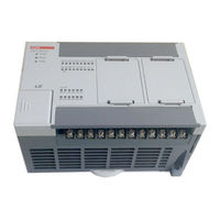
LSIS XBC-DR30E User Manual (384 pages)
XBC Standard/Economic Type Main Unit Programmable Logic Controller
Brand:
LSIS
| Category:
Controller
| Size: 14.33 MB
Table of Contents
Table of Contents
10
Chapter 1 Introduction
18
Guide to Use this Manual
18
Features
19
Introduction
20
Terminology
21
Chapter 2 System Configuration
23
XGB System Configuration
23
Product List
25
Classification and Type of Product Name
27
Classification and Type of Basic Unit
27
Classification and Type of Expansion Module
29
Classification and Type of Special Module
30
Classification and Type of Communication Module
31
System Configuration
33
Cnet I/F System
33
Ethernet System
36
Chapter 3 General Specifications
37
General Specifications
37
Chapter 4 CPU Specifications
38
Performance Specifications
38
Names of Part and Function
44
Power Supply Specifications
47
Data Backup Time
51
Chapter 5 Program Configuration and Operation Method
52
Program Instruction
52
Program Execution Methods
52
Operation Processing During Momentary Power Failure
53
Scan Time
54
Scan Watchdog Timer
56
Timer Processing
57
Counter Processing
60
Program Execution
62
Configuration of Program
62
Program Execution Methods
62
Interrupt
64
Operation Mode
76
RUN Mode
76
STOP Mode
77
DEBUG Mode
77
Change Operation Mode
81
Memory
82
Data Memory
82
Configuration Diagram of Data Memory
84
S" Type
85
Data Latch Area Setting
86
Chapter 6 CPU Functions
89
Type Setting
89
Parameter Setting
90
Basic Parameter Setting
90
I/O Parameter Setting
91
Self-Diagnosis Function
92
Saving of Error Log
92
Troubleshooting
92
Remote Functions
94
Forced Input/Output on and off Function
95
Force I/O Setup
95
Direct Input/Output Operation
97
Diagnosis of External Device
98
Allocation of Input/Output Number
99
Online Editing
101
Reading Input/Output Information
104
Monitoring
105
Program Upload Prohibit
110
Clear All PLC
111
Password Setting Per Program Block
112
Chapter 7 Input/Output Specifications
114
Introduction
114
Main Unit Digital Input Specifications
120
XBC-DR10E 6 Point DC24V Input (Source/Sink Type)
120
XBC-DR14E 8 Point DC24V Input (Source/Sink Type)
121
XBC-DR20E 12 Point DC24V Input (Source/Sink Type)
122
XBC-DR30E 18 Point DC24V Input (Source/Sink Type)
123
XBC-DN10E 6 Point DC24V Input (Source/Sink Type)
124
XBC-DN14E 8 Point DC24V Input (Source/Sink Type)
125
XBC-DN20E 12 Point DC24V Input (Source/Sink Type)
126
XBC-DN30E 18 Point DC24V Input (Source/Sink Type)
127
XBC-DP10E 6 Point DC24V Input (Source/Sink Type)
128
XBC-DP14E 8 Point DC24V Input (Source/Sink Type)
129
XBC-DP20E 12 Point DC24V Input (Source/Sink Type)
130
XBC-DP30E 18 Point DC24V Input (Source/Sink Type)
131
XBC-DN20S 18 Point DC24V Input (Source/Sink Type)
132
XBC-DN30S 18 Point DC24V Input (Source/Sink Type)
133
XBC-DR20SU 12 Point DC24V Input (Source/Sink Type)
134
XBC-DR30SU 18 Point DC24V Input (Source/Sink Type)
135
XBC-DR40SU 24 Point DC24V Input (Source/Sink Type)
136
XBC-DR60SU 36 Point DC24V Input (Source/Sink Type)
137
XBC-DN20SU 12 Point DC24V Input (Source/Sink Type)
138
XBC-DN30SU 18 Point DC24V Input (Source/Sink Type)
139
XBC-DN40SU 24 Point DC24V Input (Source/Sink Type)
140
XBC-DN60SU 36 Point DC24V Input (Source/Sink Type)
141
XBC-DP20SU 12 Point DC24V Input (Source/Sink Type)
142
XBC-DP30SU 18 Point DC24V Input (Source/Sink Type)
143
XBC-DP40SU 24 Point DC24V Input (Source/Sink Type)
144
XBC-DP60SU 36 Point DC24V Input (Source/Sink Type)
145
Main Unit Digital Output Specifications
146
XBC-DR10E 4 Point Relay Output
146
XBC-DR14E 6 Point Relay Output
147
XBC-DR20E 8 Point Relay Output
148
XBC-DR30E 12 Point Relay Output
149
XBC-DN10E 4 Point Transistor Output (Sink Type)
150
XBC-DN14E 6 Point Transistor Output (Sink Type)
151
XBC-DN20E 8 Point Transistor Output (Sink Type)
152
XBC-DN30E 12 Point Transistor Output (Sink Type)
153
XBC-DP10E 4 Point Transistor Output (Source Type)
154
XBC-DP14E 6 Point Transistor Output (Source Type)
155
XBC-DP20E 8 Point Transistor Output (Source Type)
156
XBC-DP30E 12 Point Transistor Output (Source Type)
157
XBC-DR20SU 8 Point Relay Output
158
XBC-DR30SU 12 Point Relay Output
159
XBC-DR40SU 16 Point Relay Output
160
XBC-DR60SU 24 Point Relay Output
161
XBC-DN20S(U) 8 Point Transistor Output (Sink Type)
162
XBC-DN30S(U) 12 Point Transistor Output (Sink Type)
163
XBC-DN40SU 16 Point TR Output (Sink Type)
164
XBC-DN60SU 24 Point TR Output (Sink Type)
165
XBC-DP20SU 8 Point Transistor Output (Source Type)
166
XBC-DP30SU 12 Point Transistor Output (Source Type)
167
XBC-DP40SU 16 Point TR Output (Source Type)
168
XBC-DP60SU 24 Point TR Output (Source Type)
169
Digital Input Module Specifications
170
Point DC24V Input Module (Source/Sink Type)
170
Point DC24V Input Module (Source/Sink Type)
172
Digital Output Module Specifications
173
Point Relay Output Module
173
Point Relay Output Module (Independent Point)
174
Point Relay Output Module
175
Point Transistor Output Module (Sink Type)
176
Point Transistor Output Module (Sink Type)
177
Point Transistor Output Module (Sink Type)
178
Point Transistor Output Module (Source Type)
179
Point Transistor Output Module (Source Type)
180
Point Transistor Output Module (Source Type)
181
Combined Digital I/O Module Input Specification
182
Point DC24V Input (Source/Sink Type)
182
Combined Digital I/O Module Output Specification
183
Point Relay Output
183
IO Wiring by Using Smart Link Board
184
Smart Link Board
184
Chapter 8 Built-In High-Speed Counter Function
188
High-Speed Counter Specifications
188
Performance Specifications
188
Designation of Parts
190
E" Type Functions
193
S(U)" Type Functions
210
Installation and Wiring
227
Precaution for Wiring
227
Example of Wiring
227
Internal Memory
228
Special Area for High-Speed Counter
228
Error Code
236
Examples: Using High-Speed Counter
237
Chapter 9 RTC Option Board
242
Battery
242
Battery Specification
242
Notice in Using
242
Life of Battery
242
How to Change Battery
243
RTC Function
244
How to Use
244
Name and Function of each Part
246
Chapter 10 DC Input Option Function
247
DC Input Option Board Specification
247
High Speed Counter Specification
248
Performance Specification
248
Name of each Part
249
Function
251
Installation and Wiring
255
Example of Wiring
255
Internal Memory
257
Special Area for High-Speed Counter
257
Example Using High-Speed Counter
261
Chapter11 TR Output Option Board
262
TR Output Option Board Operation Sequence of Positioning
262
Operation Sequence of Positioning
262
XBO-TN04A Specification
263
Output Option Board Specification
263
Positioning Specification
264
Performance Specification
264
Name of each Part
264
Before Positioning
266
Positioning Stop Factor
268
Manual Operation
269
Home Return
270
Positioning Basic Parameter Setup
271
Positioning Instruction List
275
Positioning Example
276
Chapter12 Memory Module
278
Memory Module Specification
278
Memory Module Structure
278
How to Use Memory Module
279
How to Use When Password Is Set
284
Chapter 13 Installation and Wiring
287
Safety Instruction
287
Fail Safe Circuit
289
PLC Heat Calculation
292
Attachment/Detachment of Modules
294
Caution in Handling
299
Wire
300
Power Wiring
300
I/O Device Wiring
303
Grounding Wiring
303
Specifications of Wiring Cable
304
Chapter 14 Maintenance
305
Maintenance and Inspection
305
Daily Inspection
305
Periodic Inspection
306
Chapter 15 Troubleshooting
307
Basic Procedure of Troubleshooting
307
Troubleshooting
307
Troubleshooting Flowchart Used with When the ERR(Error) LED Is Flickering
309
Troubleshooting Flowchart Used with When the RUN,STOP LED Turns off
310
Troubleshooting Questionnaire
313
Troubleshooting Examples
314
Input Circuit Troubles and Corrective Actions
314
Output Circuit and Corrective Actions
315
Error Code List
317
Appendix 1 Flag List
319
Appendix 1.1 Special Relay (F) List
319
Appendix 1.2 Communication Relay (L) List
329
Appendix 2 Dimension
332
Appendix 3 Compatibility with MASTER-K
337
Appendix 4 Instruction List
343
Appendix 4.1 Classification of Instructions
343
Appendix 4.2 Basic Instructions
344
Appendix 4.3 Application Instruction
347
Appendix 4.4 Special/Communication Instruction
379
Advertisement
Advertisement
Related Products
LSIS XBC-DR28U
LSIS XBC-DR28UA
LSIS XBC-DR28UP
LSIS XBC-DR20SU
LSIS XBC-DR30SU
LSIS XBC-DR40SU
LSIS XBC-DR60SU
LSIS XBC-DR10E
LSIS XBC-DR14E
LSIS XBC-DR20E
LSIS Categories
Controller
Inverter
Control Unit
DC Drives
Relays
More LSIS Manuals
Login
Sign In
OR
Sign in with Facebook
Sign in with Google
Upload manual
Upload from disk
Upload from URL