Sign In
Upload
Manuals
Brands
Long Manuals
Tractor
460 Series
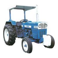
Long 460 Series Utility Tractor Manuals
Manuals and User Guides for Long 460 Series Utility Tractor. We have
2
Long 460 Series Utility Tractor manuals available for free PDF download: Service Manual, Operator's Manual
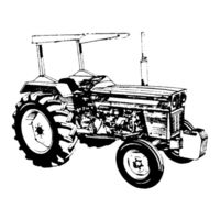
Long 460 Series Service Manual (211 pages)
Brand:
Long
| Category:
Tractor
| Size: 6.29 MB
Table of Contents
Safety Precautions
2
Master Index
3
Engine
4
Table of Contents
5
Engine Index
5
Description
6
Engine
6
Specifications • Removal • Installation a
6
Specifications
7
Circulating Water and Radiator Cooling System
7
In Case of Poor Engine Performance
8
Checking Engine Compressor with Tester
8
Fault-Finding
9
Removing Engine from Tractor
10
Front View of Tractor Without Bonnet
10
Left/Right Side View of Engine Installed
11
Disassembly and Reassembly
12
Installation
12
Instrument and Rear Panels
12
Removing Engine from Tractor with Lifting Chains
12
Engine Sectional View
13
Crankcase and Cylinder Liners
15
Checking and Cleaning the Crankcase
15
Cylinder Liner Re-Boring and Replacement
15
Checking Cylinder Liner Bore with a Dial Indicator Gauge
15
A.l CRANKCASE-CYLINDER HEAD-OIL SUMP
15
Cylinder Head
16
Standard Liner and Crankcase Bore Dimensions
16
Removing the Tappet Cover
16
Checking the Cylinder Head
17
Removing Cylinder Head from Engine Installed on Stand
17
Measuring Nozzle Projection
17
Dimensions of Intake/Exhaust Valve Seats and of Valve Guides
17
Cylinder Head and Gasket Installation
18
Oil Sump
18
Cylinder Head Tightening Sequence
18
General
19
Timing Data
19
Camshaft
19
A.ll VALVES and TIMING MECHANISM
19
Camshaft and Bearings Checks
20
Camshaft Removed
20
Replacing the Camshaft Bearings
20
Sectional View of the Camshaft Drive
20
Dimensions of Camshaft Journals and Sleeve Bearings
21
Valves, Guides and Springs
21
Grinding a Valve with Pneumatic Grinder
22
Major Dimensions of Intake/Exhaust Valves and Their Guides
22
Removing/Installing Valves and Springs
22
Measuring the Valve Gap with a Feeler Gauge
23
Tappets, Push-Rods and Rocker Arms
23
Valve Gap Adjustment
23
PMS Mark on Engine Flywheel
24
Rocker Arms and Their Supports, Springs and Shafts
24
Timing Gear Assembly
24
Phasing the Timing Gears
25
Tachourmeter
25
Timing Gear Case Oil Hole Duct
25
Bottom View of Engine Without Oil Sump
26
Crankshaft
26
A.lll CRANK GEAR ASSEMBLY
26
General
26
Removing the Pulley Hub with a Plate Puller with Slots at 120
27
Dimensions of Crankshaft Journals and of Standard Thrust Washers
27
Front/Rear End Seal Installation
28
Checking Static Balance
28
Crankcase Bearings
29
Pistons and Rings
29
Checking Running Clearance of Crankshaft Journals in Bearings
29
Installation/Removal of Thrust Washers on the Third Main Beearing
29
Dimensions of Standard Size Pistons and of Their Pins and Rings
30
Checking the Crankshaft End Float
30
Connecting Rods
31
Checking Piston Diameter at Skirt Base and at 50 MM off
31
Installation/Removal of Snap Rings with Pliers
31
Fitting a Piston Inside Its Cylinder Liner with Piston Ring Compressor
31
Installing the Connecting Rod-Piston Assemblies
32
Engine Flywheel
32
Checking Squarness of Piston Connecting Rod Assembly
32
Checking Parallelism of a Connecting Rod Axis
32
Fuel System
33
Air Cleaner
33
Air Supply
33
Fuel Supply
33
Cross-Section of Fuel Transfer Pump
34
Fuel Filters
34
Fuel Priming Pump
34
Fuel Tank
34
Bleeding the Fuel System
35
Injection Pump Fuel Circuit
36
Injection Pump
37
General Description
37
Injection Pump Removal
37
Sectional View of Injection Pump
38
Pump Adjusting
39
Injectors
39
Timing Index for Correct Pump/Engine Timing
39
Pump Installation and Timing
39
Calibrating
40
Starting Aid
40
Injector Cross-Section and Spray Pattern
40
Starting Aid Cross-Section
41
Oil Pump Parts and Assembly
42
A.V Lubrication
42
General
42
Disassembly/Reassembly of Oil Filter
43
Low Oil Pressure Warning Light
43
Oil Filter
43
Oil Pump
43
Engine Lubrication Diagram
44
Engine Oil Schedule and Capacities
45
Lube and Capacity Chart
45
Cooling
46
Engine Cooling Diagram
46
General
46
Water Pump
47
Water Pump Parts and Assembly Data
47
Radiator
48
Checking and Setting Belt Tension
49
Replacing the Fan and Alternator Drive Belt
49
Thermostat
49
Thermostat Removal/Installation
49
Check the Fan Blade Face Alignment with a Surface Gauge
50
Fan
50
Water Temperature Gauge
50
Fits and Tolerances 360/460
51
Torque Specifications Service Tools
51
Fits and Tolerances 510
54
Torque Specifications
57
Power Train
59
Power Train Index
60
General Description
61
Transmission Ratios, Performance and Weight 360 Series
61
Transmission Ratios, Performance and Weight 460/510 Center Drive DT
62
Transmission Ratios, Performance and Weight 460/510 Series
62
Power Train and Attachment Lubrication Chart
63
10" Clutch
64
Clutch Working Drawings
64
Operation
64
10" Clutch Removal
65
Removing the Front Axle/Engine Unit with Clutch from the Transmission
65
Right Side View of Tractor Without Rear Hood and Fuel Tank
65
10" Clutch Disassembly
66
Exploded View of the 10" Clutch
66
Removing/Replacing the Clutch from the Engine Flywheel
66
10" Clutch Assembly
67
10" Clutch Cross-Section
67
Inspection
67
10" Clutch Adjustments
68
Adjusting the Planeness of Clutch Disengaging Levers
68
Adjusting the PTO Release Lever Play through the Transmission Case
68
Removal/Assembling of Clutch on the Universal Stand "D"
68
10" Clutch Control Linkage Adjustment
69
Adjusting the Free Pedal Travel of the 10" Clutch
69
Clutch-Transmission Shaft Flexible Coupling
69
Phantom View of the Clutch-Transmission Shaft Coupling
69
11" Clutch
70
Clutch 11" Diagram
70
Clutch Removal
70
Removing the Engine-Axle Group with Clutch from the Power Train
70
Clutch Disassembly
71
Clutch Unit Removed
71
Removing the Release Levers Pivot Pins
71
Clutch Assembly
72
Cross Section of the 11" Clutch
72
Fitting/Removing PTO Clutch Engagement Dished Spring/Pressure Plate
72
Clutch Adjustments
73
Clutch Pedals and Control Hand Lever Free Travel Adjustment and Check
73
Fitting Clutch to Flywheel and Adjusting It Throw out Levers
73
6-Speed Transmission Gears and Shafts
74
Removing the 6-Speed Transmission
74
Speed Transmission
74
Top View and Controls
74
Dismantling the 6-Speed Transmission
75
Gearshift Lever and Gear Selector Mechanism
75
Removing/Installing the Transmission
75
Exploded View of the 6-Gear Transmission
76
Transmission Housing Installed on Engine Stand
76
Exploded View of Planetary Unit Driven Gears Support
77
Exploded View of Synchromesh Unit
77
6-Speed Transmission Assembly
78
6-Speed Transmission Cross-Section
78
Installing the Synchromesh Unit Engagement Ring
79
Installing the Synchromesh Unit Flat Springs
79
6-Speed Transmission Installation
80
6-Speed Transmission Shifter Bar, Selectors and Fork
80
Taking up the End Float of 2-5 and 3-6 Speed Drive Gear
80
8-Speed Transmission
81
Removing the 8-Speed Transmission
81
Right-Side View of the 8-Speed Transmission
81
Dismantling the 8-Speed Transmission
82
Front View of Transmission
82
Removing/Replacing the Transmission Unit 1PTO Clutch Shaft
82
Transmission Unit Installed on the Shop Turnover Stand
82
Removing the Transmission Shifter Bars
83
Removing/Refitting the Transmission Shaft Front Bearing Caps
83
Transmission Case Cover with Geear Selector Mechanism
83
Exploded View of the Planetary Unit Driven Gears Support
84
Removing the Bushing by the Sliding-Weight Puller
84
Removing the Drive Shaft a Punch
84
Removing the Reverse Gear Shaft
84
Removing the Driven Shaft
85
Removing the Reverse Gear Axle Needle Ring
85
8-Speed Transmission Cross-Sections
86
Installing the Synchromesh Unit Flat Springs and Holders
87
Fitting the Shifter Fork Bar
88
Installing the 8-Speed Transmission Driven Gears Shift
88
Fitting the Planetary Unit Shifter Fork and Bar
89
Fitting the Transmission Speed Selector/Shifter Forks Split Dowel Pins
89
Replacing/Removing the Reverse Gear Shifter Fork
90
Transmission Installation
90
Bevel Gear and Differential
91
Dismantling the Bevel Gear and Differential
91
Hoisting off the Rear Bevel Gear Unit
91
Removing Tghe Rear Bevel Gear Housing
91
Exploded View of the Differential and Bevel Gear
92
Pulling the Differential Tapered Roller Bearings
92
Bevel Gear and Differential Assembly
93
Bevel Gear and Differential Cross-Sectional View
93
Adjusting the Bevel Gear Pinion Shaft Tapered Roller Bearings
94
Bevel Gear Setting
94
Fitting/Removing the Differential Bearing Housing
94
Arrangement of Cone Center Distance Caliper
95
Arrangement of Cone Center Distance Caliper Shaft
95
Tightening the Nut with the Torque Wrench
95
Sample Layouts of Two Pinion Cone Center Distance Settings
96
Adjusting the Differential Gear Tapered Roller Bearing
97
Measuring the Clearance with a Feeler Gauge
97
Tightening the Nuts with a Torque Wrench
97
Brakes
98
Disassembly
98
Service and Parking Brakes and Their Controls
98
Adjustment
99
Assembly
99
Exploded View of a Service Brake
99
Assembling the Double Intermediate Gear
100
Assembling the Independent Hand Brake
100
Independent Hand Brake
100
Removal of Double Intermediate Gear
100
Cross-Section of the Rear Axle with Side PTO and Hand Brake
101
Independent Hand Brake Adjustment
102
Final Drives and Rear Wheels
103
Removing the Brake Drum Locknut
103
Removing/Replacing the Right Hand Side Final Drive
103
Final Drive Housing
104
Removing the Bull Gear by Means of a Puller
104
Removing the Bull Gear Locknut
104
Cross-Sectional View of One Final Drive
105
Pulling out the Pinion Shaft Outer Roller Bearing Inner Race
105
Removing/Replacing the Bull Gear Shaft
106
Overhauling
107
Power Take-Off
107
PTO and PTO Control Installation
107
PTO Cross-Section
108
Front Axle and Steering
109
Removing the Cup of the Lower Tapered Roller Bearing
109
Removing the Steering Arm from the Steering Box Nut
109
Steering Box
109
Removing the Steering Box Nut Shaft Bushing by Means of a Puller
110
Steering Box Cross-Section
110
Adjusting the Steering Shaft Tapered Roller Bearings
111
Adjusting the Worm-And-Nut Setting
111
Steering Box Adjustments
111
Front Axle Left End
112
Overhaul
112
Removing the Trunnion Pin by Means of a Slide Puller and Adaptor
112
Front Axle Cross-Section
113
Removing the Steering Lever Pivot
113
Removing the Bushing from the Front Axle Bracket
114
Replacing/Removing the Steering Spindle Complete with Wheel Hub
114
Self-Lubricating Ball Joint
114
Checking the Front Wheel Alignment
115
Front Axle Checks
115
Front Drive Axle
116
Front Drive Axle Removal
116
Removing the Front Drive Axle
116
Removing the Front Drive Axle Swinging Axle
116
Removal of Splined Hub
117
Withdrawing the Joint Axis
117
Withdrawing the Outer Axis Bushing of the Flange
117
Withdrawing the Steering Lever Axle
117
Differential and Bevel Gearing
118
Withdrawing the Bushings of the Front Drive Axle Swinging Shaft
118
Front Drive Axle Cross-Section
119
Hub and Left Joint Components
119
Assembling the Spider Pinions into the Casing and Bevel Gearing
120
Reassembly
120
Establishing the Thickness of Shims
121
Bevel Pinion Setting
122
Checking the Differential Drive Pinion Adjustment
122
The Assembling Positions of the Stop and of the Steering Stop Plate
122
Adjustment of the Steering Axis Beaing Clearance
123
To Assemble the Joint Casing with the Spherical Support
123
Adjustment of Wheel Hub Bearings
124
Assembling the Wheel Hub
124
Running-In of the Front Drive Axle
124
Setting the Front Drive Axle
124
Dismantling the Front Drive Axle Reduction Gear
125
Front Drive Axle Reduction Gear
125
Reduction Gear Description and Operation
125
Removing the Front Drive Axle Reduction Gear from the Tractor
125
Front Drive Axle Reduction Gear Cross-Section
126
Front Drive Axle Reduction Gear, Dismantled in Its Components
126
Assembling the Front Drive Axle Side Reduction Gear
127
Assembling the Secondary Shaft in the Rear Bearing
127
Assembling the Reduction Gear on the Tractor
128
Front Wheel Toe-Out
128
Reduction Gear Running-In
128
The Adjustment of the Front Drive Axle Side Reduction Gear
128
Planetary Drive Removal and Disassembly
130
Removing/Installing the Spindle Nut
130
Removing Bearing from Ring Gear Support, Spindle
131
Checking Hub Bearing Preload
132
Planetary Drive Reassembly
132
Shiming Trunnion
132
Axle Inspection/Reassemble
133
Axle Removal/Disassembly
133
Axle Shaft Disassemble
133
Differential Removal/Disassembly
133
Differential Reassembly
134
Differential Support
134
Differential Support Removed from Axle Housing
134
Pinion Support
134
Checking Backlash of Pinion and Ring Gear
135
Checking Rolling Torque of Differential
135
Checking Rolling Torque of Pinion Shaft
135
Checking/Adjusting the Pinion Shaft and Ring Gear Tooth Contact
135
Independent Handbrake Controls
136
Reduction Gearbox
136
LH Reduction Gearbox
137
Reduction Gearbox Installed
137
Remove Shaft
137
Top View, Reduction Gearbox
137
Stacking of Parts, Reduction Gearbox
138
Data, Fits, Wear Limits, Torque Specifications
139
Hydraulics
151
Hydraulic Lift and Power Steering Index
152
Hydraulic Lift and Power Steering
153
Hydraulic Lift Installed on Tractor
153
Hydraulic Lift
154
Hydraulic Lift Setting for Position Control Operation
154
Position Control
154
Draft Control
155
Floating Position
155
Hydraulic Working Diagram of Lift Unit Using Transmission Oil
155
Oil Flow Pattern Inside the Hydraulic Control Valve/Power Cylinder
156
Lift Hydraulics
157
Mechanics of the Draft Control Operation
157
Mechanics of the Hydraulic Lift Position Control Operation
157
Control Valve Removal
158
Hydraulic Control Valve Cutout
158
Removing the Hydraulic Lift Piston and Cylinder Barrel
158
Schematic Diagram of the Valve Spool Control Leverage
159
Hydraulic Lift Removal
160
Removing the Rear Cover
160
Removing the Rocker Shaft from the Hydraulic Lift Unit
160
External/Internal Spool Control Leverage
161
Removing the Internal Control Leverage
161
Rocker Shaft Cross-Sectional View
162
Assembly Marks for Installation of Internal Arm and Lift Arms
163
Fitting the Sealing Rings to the Rockshaft
163
Checking and Servicing the Hydraulic Lift Oil Filter
164
Right Side Lift Rod
164
Three-Point Linkage
164
Rear View of the Hydraulic Lift and Three-Point Linkage
165
Right Side Lift Rod Section
165
Adjusting the Control Spring Setting
166
Setting the Control Spring Movement
166
Adjusting the Maximum Lift Arm Travel
167
Sensitivity Adjustment
167
Setting the Maximum Lift Arms Travel
167
Adjusting the Draft Control Operating Range
168
Checking Control Valve Spool Sensitivity
168
Control Lever Quadrant Draft Control Range
168
Control Valve Spool Section
168
Adjusting the Draft Control Range
169
Checking the Draft Control Operating Range
169
Checking the Drain Valve Tightness
169
Checking the Pressure Relief and Safety Valve Calibration
169
Leak down Remote Ram
170
Remote Hydraulic System
170
Hydraulics Working Diagram
171
Optional Pressure Connection Fitted to the Control Valve
171
Exploded View of Hydraulic Pump
172
Hydraulic Pump
172
Pump Driving Unit
172
Polishing Drive Gear Faces
173
Bearing and Gear End Clearance Measurement
174
Installing the Seal Back up Ring to the Pump Cover on the Inner O-Ring
174
Troubleshooting Chart
175
Neutral Position
176
Power Steering
176
Retracted Position - Left/Right Turn
176
Steering System
176
Working Diagrams of Power Steering Cylinder
177
Power Steering Cylinder
178
Cylinder Disassembly
179
Disassembly and Assembly of Control Valve Group
179
Disassembly and Assembly of Minor - Pressure End of Cylinder
179
Front End of Cylinder
179
Disassembly and Assembly of Cylinder Rod
180
Installing Control Valve Rod and Head Body Assembly
180
Installing Cylinder Rod and Piston Assembly
180
Service of Front End Body
180
Separate Hydraulic Oil Reservoir
181
Hydrostatic Steering
183
Hydraulic Diagram of Hydraulic System
184
Left Turn
184
Reservoir (Tank)
185
Right Turn
185
Servicing the Hydrostatic Steering System
185
Turning When the Oil Pump Is Inoperative
185
Cylinder Assembly
186
Hydrostatic Steering Cylinder
186
Fits and Tolerances - Torque Specifications Service Tools
187
Electrical System
189
Electrical System Index
190
Wiring Diagram
191
Battery Charging Equipment
192
Battery Charging Equipment Wiring Diagram
192
General
192
Alternator
192
Stator
192
Alternator Without End Shields
193
Fundamental Circuit of Alternator
193
The Rotor
193
The Stator
193
Bracket Shield
194
Bracket Shield and Diode Holder Unit
194
End Shield
194
Alternator Operation
195
Alternator Specifications
195
Diode Holder Unit
195
Diode Specifications
196
Instructions for Checking Diodes
196
Rectifying Diodes
196
Wiring Diagram of the 3-Phase Bridge-Connected Rectifier
196
Alternator Disassembly
197
Rectifier Diode Replacement
197
Service Instructions
197
Alternator Assembly
198
Brush-Holder Assembly
198
Cross-Sectional View of Alternator
198
Replacing the Brushes
198
Check at Assembly
199
Installation on the Tractor
199
Maintenance Instructions
199
Operation Instructions
199
Battery Charge Warning Light Relay
200
Bottom View of Alternator Warning Relay
200
Troubleshooting the Battery Charging System on the Tractor
200
Voltage Regulator
200
Trouble Shooting Guide in Case of Irregular Warning Light Operation
201
0.11 Starter
203
Starter Characteristics
203
Test Instructions for Starter Check
203
Test Wiring Diagram of Starter
203
Wiring Diagram of Starter
203
Service Instructions
204
Starter Dismantling
204
Stator Assembly
204
Trouble Shooting Instructions
204
Armature
205
Inspection and Permissible Repairs
205
Reassembly
205
Sectional View of the Starter
205
Bearings
206
Checking Collector Excentricity Using a Dial Indicator Gauge
206
Checking the Insulation to the Ground of the Armature Winding
206
Checking the Mica of the Collector
206
Checking Continuity of an Armature Winding
207
Checking for Short Circuits Across the Armature Winding Conductions
207
Checking the Insulation to Ground of a Field Winding
207
Induction Fields
207
Engagement Unit
208
Starter Contacts and Solenoid Switches
208
Troubles in Starter Operation Causes and Their Remedies
208
Troubles, Causes and Remedies
208
Specifications, Starter
209
Advertisement
Long 460 Series Operator's Manual (88 pages)
Brand:
Long
| Category:
Tractor
| Size: 4.82 MB
Advertisement
Related Products
Long 460DT
Long 2360
Long 2360 DTC
Long 360 Series
Long 510 Series
Long Categories
Tractor
More Long Manuals
Login
Sign In
OR
Sign in with Facebook
Sign in with Google
Upload manual
Upload from disk
Upload from URL