Sign In
Upload
Manuals
Brands
Lombardini Manuals
Engine
LGA 280 OHC Series
Lombardini LGA 280 OHC Series Manuals
Manuals and User Guides for Lombardini LGA 280 OHC Series. We have
2
Lombardini LGA 280 OHC Series manuals available for free PDF download: Manual, Workshop Manual
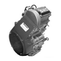
Lombardini LGA 280 OHC Series Manual (82 pages)
1-5302-714
Brand:
Lombardini
| Category:
Engine
| Size: 1.74 MB
Table of Contents
General Service Manual Notes
3
Table of Contents
4
1 Trouble Shooting
7
Warning Signs - Safety Instructions
8
Engine Identification
10
III Engine Identification
10
4 Technical Features
11
5 Characteristics
12
6 Overall Dimension
14
7 Maintenance - Recommended Oil Type - Refilling
15
Engine Oil - Change
18
Engine Oil - Refilling
18
Oil Dipstick - Check
18
Oil Level - Check
18
8 Disasssembly/Reassembly
19
Air Shroud and Side Plates - Disassembly
19
Engine Preparation
19
Coil - Disassembly
20
Fan Flywheel- Disassembly
20
Magnet
20
Alternator Stator - Disassembly
21
Alternator Support - Disassembly
21
Alternator with Permanent Magnets
21
Timing Belt External Cover - Disassembly
21
Disassembly of Camshaft Timing Synchronous Belt
22
Lower Guard of Synchronous Timing Belt - Disassembly
22
Timing Synchronous Belt - Disassembly
22
Camshaft Timing Synchronous Belt - Extraction
23
Driving Shaft Timing Synchronous Belt
23
Timing Belt Internal Cover - Disassembly
23
Air Valve Union
24
Oil Filter - Disassembly
24
Recirculation Vent System
24
Head Sump Lubrication Pipe
25
Oil Sump - Disassembly
25
Oil Pump Cover
26
Oil Pump Cover Extraction
26
Oil Sealing Ring Insertion
26
Sealing Ring Extraction (30X47X7)
26
Housing Cover, Power Take-Off Side - Disassembly
27
Oil Pump Rotors
27
Oil Pressure Regulating Valve
28
Oil Pressure Regulating Valve Components
28
Power Take-Off Side Cover - Disassembly
28
Camshaft Support - Head Disassembly
29
Tappet Cover Disassembly
29
Camshaft (Head Disassembly)
30
Camshaft Dimensional Check
30
Timing Diagram
31
Centrifugal Decompression Device - Operation with the Engine Running
32
Centrifugal Decompression Device - Operation with the Engine Stopped
32
Centrifugal Decompression Device
32
Head - Disassembly
32
Tappet and Seat Dimensional Check (MM)
33
Tappets - Removal
33
Tappets
33
Valve Clearance Adjusting Pads - Correct Assembling Order
33
Camshaft Support Ball Bearing - Disassembly from Head
34
Oil Sealing Rings on Valve Stem - Disassembly
34
Valves - Disassembly
34
Wrist Pin Housing in Piston - Check
34
Cylinder Head
35
Valves - Check
35
Valve Guides - Check
36
Guide Protrusion from Cylinder Head Surface
37
Valve Guides - Assembly
37
Valve Guides - Removal
37
Valve Guides - Seats - Replacement
37
Valve Seats
38
Loaded Valve Springs - Check
39
Valve Housings and Seats - Dimensions
39
Valve Springs - Check
39
Valve Stem Seal Rings Positioned on the Valve Guides - Assembly Ref. No. 4535.015
39
Camshaft Support Bearing 17X40X12, Distribution Side - Assembly
40
Connecting Rod Cap Fixing Bolts - Disassembly
40
Oil Seal Ring 17X40X7 for Camshaft Support, Distribution Side - Assembly
40
Oil Seal Ring for Camshaft Support, Distribution Side - Disassembly
40
Connecting Piston Pin - Disassembly
41
Connecting Rod / Piston Wrist Pin Lock Tension Washer - Disassembly
41
Connecting Rod Cap - Disassembly
41
Piston and Connecting Rod - Disassembly
41
Crankshaft - Disassembly
42
Crankshaft Support Bearing - Disassembly
42
Driving Shaft - Check
42
Connecting Rod Equipped with Bearings and Wrist Pin
43
Pin Diameters - Threads - Connecting Radius (MM) - Check
43
Piston and Piston Rings - Check
44
Retaining Rings - Check for Wear
44
Cylinder
45
Retaining Rings - Correct Installation Direction
45
Crankshaft - Reassembly
46
Insertion of Crankshaft Bearings on the Flywheel Side
46
Oil Seal Ring in Flywheel Side Housing - Assembly
46
Oil Seal Ring in Flywheel Side Housing - Disassembly
46
Camshaft Toothed Synchronous Timing Pulley
47
Piston and Connecting Rod
47
Power Take-Off Side Cover - Assembly
47
Camshaft - Reassembly
48
Cylinder Head - Assembly
48
Gasket between Cylinder and Head - Assembly
48
Camshaft Control Pulley Key - Assembly
49
Camshaft Support - Assembly
49
Camshaft Synchronous Pulley
49
Internal Protective Guard for Timing Belt - Reassembly
49
Belt Tightener - Reassembly
50
Crankshaft Toothed Synchronous Pulley
50
Timing System: Camshaft Synchronous Pulley
50
Synchronous Timing Belt
51
Timing System: Crankshaft Synchronous Pulley
51
Alternator Support - Assembly
52
Cable Clamp Plate for Alternator Stator - Assembly
52
External Cover of the Lower Toothed Timing Belt - Assembly
52
Lower Toothed Timing Belt Cover - Assembly
52
Air Gap Adjustment Coil - Assembly
53
Alternator Stator - Assembly
53
Fan Flywheel - Assembly
53
Lateral Cooling Air Shroud - Intake Side
53
Air Valve - Assembly
54
Clearance - Check
54
Cooling Air Shroud, Flywheel Side - Assembly
54
Lateral Cooling Air Shroud - Exhaust Side
54
Clearance - Adjustment
55
Intake Manifold - Assembly
56
Spark Plug - Assembly
56
Spark Plug - Tightening
56
Tappet Cover - Assembly
56
SPACO Carburetor Type FSY 22 - Assembly
57
Starting Motor Locking Clip
57
Starting Motor: SICE 0001A/NO 12 V 0,25 Kw R.sx - Assembly
57
9 Lubrication System
58
Electrical Starting System 180 W Diagram
59
10 Xelectrical System
60
Starting Motor
60
Starting Motor - Brushes Replacement
61
Starting Motor - Clutch Pinion Replacement
61
Starting Motor - Exploded View
61
Starting Motor - Brushes Replacement
62
X Electrical System
62
Electronic Ignition
63
Electronic Ignition: Operating Principle
63
Check Continuity of Alternator with Stopped Motor
64
Checking the Ground Insulating Alternator with Engine Stopped
64
Coil Check : Engine Not Started
64
Alternator Efficiency Check with Engine Running
65
Tension Control Checking (Engine Started)
67
11 Inyection System
68
Carburettor Type SPACO : FSY 22
68
Fuel System
68
Idling Circuit
69
Maximum Operation
70
Progression System
70
XI Inyection System
70
Starter Circuit
71
12 Storage
72
XII Storage
73
13 Installation - Inclination Limits of Operation
74
14 Torque Settings - Torque Specifications
75
15 Special Tools
78
Advertisement
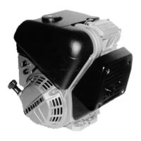
Lombardini LGA 280 OHC Series Workshop Manual (45 pages)
OHC Series
Brand:
Lombardini
| Category:
Engine
| Size: 4.51 MB
Table of Contents
General Service Manual Notes
2
Warranty Certificate
3
Troubleshooting
7
Warning Signs - Safety Instructions
8
Engine Identification Number
10
Technical Features
11
Engine Type
11
Characteristics Power, Torque and Specific Fuel Consumption Curves
12
Overall Dimensions
13
Maintenance
14
Operation
14
Recommended Oil
15
Acea Sequences
15
Cylinder Head
18
Valve Guides
20
Valve Seats
21
Valve Springs
22
Breather Valve
22
Connecting Rod
23
Piston and Rings
23
Drive Shaft
25
Speed Governor
26
Recoil Starter
27
Piston and Connecting Rods
28
Timing Cover
29
Cylinder Head Assembly
29
Electronic Ignition
33
Spark Plug
33
System Checks
34
Starter Motor
35
Engine Assembly
36
Engine Test
36
Electric Starting
37
Preparation for Starting
38
Installation - Inclination Limits of Operation
39
Torque Settings
40
Standard Bolt Torque Specifications
41
Special Tools
42
Advertisement
Related Products
Lombardini LGA 280 OHC
Lombardini LGA 226
Lombardini LGA 340 OHC
Lombardini LGW 523 Series
Lombardini LGW 627 Series
Lombardini LGW 523 mpi
Lombardini 9 LD 626-2 NR
Lombardini LMG 6000
Lombardini LDW 492 DCI
Lombardini LDW 2004
Lombardini Categories
Engine
Air Conditioner
Controller
More Lombardini Manuals
Login
Sign In
OR
Sign in with Facebook
Sign in with Google
Upload manual
Upload from disk
Upload from URL