Sign In
Upload
Manuals
Brands
LMI Technologies Manuals
Accessories
Gocator 2500 Series
LMI Technologies Gocator 2500 Series Manuals
Manuals and User Guides for LMI Technologies Gocator 2500 Series. We have
2
LMI Technologies Gocator 2500 Series manuals available for free PDF download: User Manual, Quick Start Manual
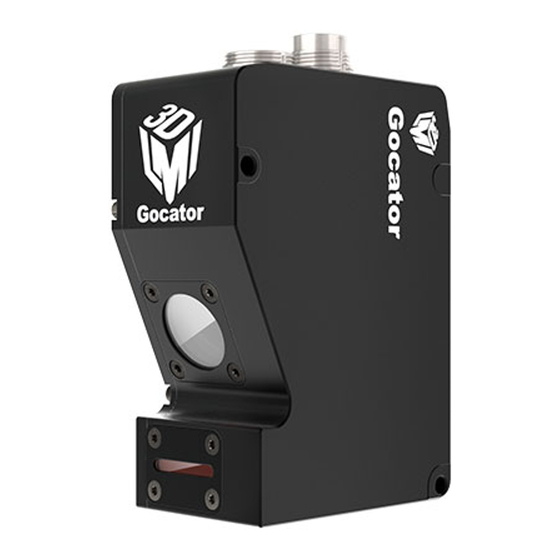
LMI Technologies Gocator 2500 Series User Manual (800 pages)
Line Profile Sensors
Brand:
LMI Technologies
| Category:
Accessories
| Size: 41.8 MB
Table of Contents
Copyright
2
Table of Contents
3
Gocator Line Profile Sensors: User Manual
7
Introduction
13
Gocator Overview
14
Safety and Maintenance
15
Laser Safety
15
Laser Classes
16
Precautions and Responsibilities
17
Class 3B Responsibilities
17
Nominal Ocular Hazard Distance (NOHD)
18
Systems Sold or Used in the USA
19
Electrical Safety
20
Heat Warning
20
Handling, Cleaning, and Maintenance
20
Environment and Lighting
21
Getting Started
22
Hardware and Firmware Capabilities
22
Hardware Overview
23
Gocator Sensor
23
Gocator Cordsets
23
Master 100
24
Master 400 / 800 / 1200 / 2400
25
Master 810 / 2410
26
Alignment Targets
28
System Overview
29
Standalone System
29
Dual-Sensor System
30
Multi-Sensor System
31
Installation
33
Mounting
33
Orientations
34
Grounding
36
Gocator
36
Recommended Practices for Cordsets
36
Master Network Controllers
37
Additional Grounding Schemes
38
Grounding When Using a DIN Rail (Master 810/2410)
38
Installing DIN Rail Clips: Master 810 or
38
Configuring Master 810
40
Encoder Quadrature Frequency
41
Setting the Divider
41
Setting the Debounce Period
42
Rut-Scanning System Setup
42
Layout
42
Software Configuration
43
System Setup
43
System Operation
44
Network Setup
45
Client Setup
45
Gocator Setup
48
Running a Standalone Sensor System
48
Running a Dual-Sensor System
49
Next Steps
51
How Gocator Works
53
3D Acquisition
53
Clearance Distance, Field of View and Measurement Range
54
Resolution and Accuracy
55
Resolution
55
Z Linearity
56
Z Resolution
56
Profile Output
58
Coordinate Systems
58
Sensor Coordinates
58
System Coordinates
59
Part and Section Coordinates
62
Switching between Coordinate Systems
63
Resampled Data and Point Cloud Data
63
Data Generation and Processing
65
Surface Generation
65
Part Detection
65
Sectioning
66
Part Matching
66
Measurement
67
Tool Chaining
67
Anchoring Measurements
68
Geometric Features
70
Tool Data
73
Output and Digital Tracking
77
Gocator Web Interface
79
Browser Compatibility
79
Internet Explorer 11 Issues
79
Internet Explorer Switches to Software Rendering
79
Internet Explorer Displays "Out of Memory
79
User Interface Overview
80
Toolbar
82
Creating, Saving and Loading Jobs (Settings)
82
Recording, Playback, and Measurement Simulation
83
Recording Filtering
85
Downloading, Uploading, and Exporting Replay Data
87
Metrics Area
89
Data Viewer
90
Status Bar
90
Log
90
Frame Information
91
Quick Edit Mode
91
Interface Language
92
Management and Maintenance
93
Manage Page Overview
93
Sensor System
94
Dual- and Multi-Sensor Systems
94
Buddy Assignment
95
Over Temperature Protection
96
Sensor Autostart
96
Layout
96
Device Exposure Multiplexing
103
Networking
104
Motion and Alignment
105
Alignment Reference
105
Encoder Resolution
106
Encoder Value and Frequency
106
Travel Speed
106
Jobs
107
Security
108
Maintenance
109
Sensor Backups and Factory Reset
110
Firmware Upgrade
111
Support
112
Support Files
113
Manual Access
113
Software Development Kit
114
Scan Setup and Alignment
115
Scan Page Overview
115
Scan Modes
116
Triggers
117
Trigger Examples
121
Trigger Settings
122
Maximum Input Trigger Rate
124
Maximum Encoder Rate
124
Sensor
124
Active Area
124
Tracking Window
126
Transformations
128
Exposure
129
Single Exposure
130
Dynamic Exposure
131
Multiple Exposure
132
Spacing
134
Sub-Sampling
134
Spacing Interval
135
Advanced
136
Camera Gain and Dynamic Exposure
137
Material
137
Alignment
138
Alignment Types
138
Aligning Sensors
139
Encoder Calibration
145
Clearing Alignment
146
Filters
146
Gap Filling
147
Median
147
Smoothing
148
Decimation
149
Surface Generation
149
Part Detection
153
Part Detection Status
157
Edge Filtering
159
Data Viewer
160
Data Viewer Controls
160
Video Mode
163
Exposure Information
163
Exposures
163
Overexposure and Underexposure
164
Spots and Dropouts
165
Profile Mode
166
Surface Mode
168
Height Map Color Scale
171
Sections
172
Region Definition
173
Intensity Output
174
Models
176
Model Page Overview
176
Part Matching
176
Using Edge Detection
177
Creating a Model
180
Modifying a Model's Edge Points
182
Adjusting Target Sensitivity
185
Running Part Matching
186
Setting the Match Acceptance Criteria
186
Using Bounding Box and Ellipse
186
Running Part Matching
189
Using Part Matching to Accept or Reject a Part
190
Sections
190
Creating a Section
193
Deleting a Section
195
Measurement and Processing
196
Measure Page Overview
196
Data Viewer
197
Tools Panel
198
Adding and Configuring a Measurement Tool
198
Stream
199
Regions
201
Source
201
Feature Points
204
Geometric Features
206
Decisions
208
Fit Lines
208
Filters
209
Measurement Anchoring
211
Enabling and Disabling Measurements
216
Editing Tool, Input, or Output Names
217
Changing a Measurement ID
217
Duplicating a Tool
218
Removing a Tool
218
Reordering Tools
219
Profile Measurement
220
Advanced Height
220
Measurements, Data, and Settings
222
Master Comparison
223
Anchoring
224
Correction
224
Reference Line
224
Area
225
Measurements, Features, and Settings
226
Bounding Box
229
Measurements, Features, and Settings
230
Bridge Value
232
Understanding the Window and Skip Settings
232
Measurements and Settings
233
Using Window and Stddev as Metrics Measurements
235
Circle
237
Measurements, Features, and Settings
237
Closed Area
240
Measurements and Settings
240
Dimension
244
Measurements and Settings
244
Groove
247
Measurements, Features, and Settings
248
Intersect
252
Measurements, Features, and Settings
252
Line
255
Measurements, Features, and Settings
256
Panel
259
Position
263
Measurements, Features, and Settings
263
Round Corner
265
Strip
269
Script
274
Surface Measurement
276
Ball Bar
277
Bounding Box
280
Measurements, Features, and Settings
281
Countersunk Hole
285
Measurements, Features, and Settings
287
Dimension
294
Edge
298
Paths and Path Profiles
300
Measurements, Features, and Settings
301
Ellipse
312
Measurements, Features, and Settings
313
Extend
315
Data and Settings
316
Filter
318
Settings and Available Filters
319
Flatness
321
Measurements, Data, and Settings
322
Hole
327
Measurements, Features, and Settings
329
Measurement Region
331
Opening
333
Measurements, Features, and Settings
336
Measurement Region
340
Plane
341
Measurements, Features, and Settings
343
Position
345
Measurements, Features, and Settingss
346
Measurements, Data, and Settings
350
Section 347 Measurements, Data, and Settings
350
Segmentation
356
Measurements, Data, and Settings
358
Sphere
363
Measurements, Features, and Settings
364
Stitch
366
Measurements, Data, and Settings
367
Stud
370
Measurements, Features, and Settings
372
Measurement Region
373
Track
374
Key Concepts
376
Track Location
378
Peak Detection
379
Side Detection
379
Center Point Detection
380
Configuring the Track Tool
380
Measurements, Data, and Settings
381
Anchoring
385
Using the Track Editor
386
Transform
389
Combinations of Geometric Feature Inputs and Results
392
Plane
392
Line
393
Point
394
Plane + Line
395
Plane + Point
396
Line + Point
397
Plane + Line + Point
398
Measurements, Data, and Settings
400
Vibration Correction
402
Data and Settings
403
Volume
404
Script
407
Feature Measurement
408
Create
409
Line from Two Points
410
Perpendicular or Parallel Line from Point and Line
411
Circle from Points
412
Line from Two Planes
413
Point from Three Planes
414
Point or Line
414
Dimension
417
Intersect
421
Robot Pose
425
Measurements and Settings
427
Scripts
427
Built-In Script Functions
428
Output
433
Output Page Overview
433
Ethernet Output
434
Digital Output
438
Analog Output
441
Serial Output
443
Dashboard
446
Dashboard Page Overview
446
State and Health Information
446
Statistics
448
Measurements
448
Performance
448
Gocator Acceleration
450
Benefits
451
Dashboard and Health Indicators
451
Hardware Acceleration: Gomax
451
Software-Based Acceleration
451
System Requirements and Recommendations
452
Minimum System Requirements
452
Recommendations
452
Installation
452
Gocator Accelerator Utility
452
SDK Application Integration
455
Estimated Performance
455
Gocator Emulator
457
System Requirements
457
Limitations
458
Downloading a Support File
458
Running the Emulator
459
Adding a Scenario to the Emulator
460
Running a Scenario
461
Removing a Scenario from the Emulator
462
Using Replay Protection
462
Stopping and Restarting the Emulator
463
Running the Emulator in Default Browser
463
Working with Jobs and Data
464
Creating, Saving, and Loading Jobs
464
Playback and Measurement Simulation
464
Downloading, Uploading, and Exporting Replay Data
466
Downloading and Uploading Jobs
468
Scan, Model, and Measurement Settings
470
Calculating Potential Maximum Frame Rate
470
Protocol Output
471
Remote Operation
471
Gocator Device Files
473
Live Files
473
Log File
473
Job File Structure
474
Job File Components
474
Accessing Files and Components
475
Configuration
475
Setup
476
Backgroundsuppression
477
Filters
477
Xsmoothing
478
Ysmoothing
478
Xgapfilling
478
Ygapfilling
478
Xmedian
479
Ymedian
479
Xdecimation
479
Ydecimation
479
Xslope
479
Yslope
480
Trigger
480
Layout
482
Alignment
483
Disk
484
Bar
484
Plate
484
Polygon
485
Polygon/Corner
485
Devices / Device
485
Surfacegeneration
491
Fixedlength
492
Variablelength
492
Rotational
492
Surfacesections
492
Profilegeneration
493
Fixedlength
493
Variablelength
494
Rotational
494
Partdetection
494
Edgefiltering
496
Partmatching
496
Edge
496
Boundingbox
497
Ellipse
497
Replay
498
Recordingfiltering
498
Conditions/Anymeasurement
498
Conditions/Anydata
499
Conditions/Measurement
499
Streams/Stream (Read-Only)
499
Tooloptions
500
Measurementoptions
501
Featureoptions
501
Streamoptions
502
Tools
502
Profile Types
502
Profilefeature
502
Profileline
503
Profileregion2D
503
Surface Types
503
Region3D
503
Surfacefeature
503
Surfaceregion2D
504
Geometric Feature Types
504
Parameter Types
504
Profilearea
506
Profileboundingbox
508
Profilebridgevalue
510
Profilecircle
511
Profiledimension
513
Profilegroove
515
Profileintersect
517
Profileline
519
Profilepanel
521
Profileposition
523
Profileroundcorner
525
Profilestrip
527
Script
529
Surfaceboundingbox
530
Surfacecshole
532
Surfacedimension
535
Tool (Type Surfaceedge)
537
Surfaceellipse
540
Surfacehole
542
Surfaceopening
544
Surfaceplane
547
Surfaceposition
549
Surfacestud
551
Surfacevolume
553
Tool (Type Featuredimension)
555
Tool (Type Featureintersect)
557
Custom
558
Output
559
Ethernet
559
Ascii
562
Eip
562
Modbus
562
Profinet
562
Digital0 and Digital1
563
Analog
564
Serial
564
Ascii
565
Selcom
565
Transform
566
Device
567
Part Models
567
Edge Points
568
Configuration
569
Protocols
570
Gocator Protocol
570
Data Types
571
Commands
571
Discovery Commands
572
Get Address
572
Set Address
573
Get Info
574
Control Commands
575
Get Address
576
Protocol Version
576
Get System Info V2
577
Set Address
577
Get System Info
580
Get States
581
Change Password
582
Log In/Out
582
Assign Buddies
583
List Files
584
Remove Buddies
584
Set Buddy
584
Copy File
585
Read File
585
Write File
586
Delete File
587
User Storage Free
587
User Storage Used
587
Get Default Job
588
Set Default Job
588
Get Loaded Job
588
Get Alignment Reference
589
Set Alignment Reference
589
Clear Alignment
590
Get Timestamp
590
Get Encoder
590
Reset Encoder
591
Start
591
Scheduled Start
592
Stop
592
Get Auto Start Enabled
592
Set Auto Start Enabled
593
Get Voltage Settings
593
Set Voltage Settings
594
Get Quick Edit Enabled
594
Set Quick Edit Enabled
594
Start Alignment
595
Start Exposure Auto-Set
595
Software Trigger
596
Schedule Digital Output
596
Schedule Analog Output
597
Ping
597
Reset
598
Backup
598
Restore
599
Restore Factory
599
Get Recording Enabled
600
Set Recording Enabled
600
Clear Replay Data
601
Get Playback Source
601
Set Playback Source
601
Simulate
602
Seek Playback
602
Step Playback
603
Playback Position
603
Clear Measurement Stats
604
Read Live Log
604
Clear Log
604
Simulate Unaligned
605
Acquire
605
Acquire Unaligned
605
Create Model
606
Detect Edges
606
Add Tool
607
Add Measurement
607
Read File (Progressive)
608
Export CSV (Progressive)
608
Export Bitmap (Progressive)
609
Get Flag
610
Set Flag
610
Get Runtime Variable Count
611
Set Runtime Variables
611
Get Runtime Variables
612
Upgrade Commands
612
Start Upgrade
612
Start Upgrade Extended
613
Get Upgrade Status
613
Get Upgrade Log
614
Results
614
Data Results
614
Stamp
615
Video
616
Profile Point Cloud
617
Uniform Profile
617
Profile Intensity
618
Uniform Surface
619
Surface Intensity
619
Surface Section
620
Surface Section Intensity
621
Measurement
621
Alignment Result
622
Exposure Calibration Result
623
Edge Match Result
623
Bounding Box Match Result
623
Ellipse Match Result
624
Event
624
Feature Point
625
Feature Line
625
Feature Plane
625
Feature Circle
626
Generic Message
626
Health Results
626
Modbus Protocol
632
Concepts
632
Messages
632
Registers
633
Control Registers
634
Output Registers
635
State
635
Stamp
636
Measurement Registers
637
Ethernet/Ip Protocol
639
Explicit Messaging
639
Identity Object (Class 0X01)
640
TCP/IP Object (Class 0Xf5)
640
Ethernet Link Object (Class 0Xf6)
641
Assembly Object (Class 0X04)
641
Command Assembly
641
Runtime Variable Configuration Assembly
642
Sensor State Assembly
643
Sample State Assembly
644
Implicit Messaging
646
Assembly Object (Class 0X04)
646
Implicit Messaging Command Assembly
646
Implicit Messaging Output Assembly
647
PROFINET Protocol
649
Control Module
649
Runtime Variables Module
650
State Module
650
Stamp Module
651
Measurements Module
651
ASCII Protocol
652
Connection Settings
652
Ethernet Communication
652
Serial Communication
653
Polling Operation Commands (Ethernet Only)
653
Command and Reply Format
654
Special Characters
654
Command Channel
654
Start
655
Stop
655
Trigger
655
Loadjob
656
Stamp
656
Clear Alignment
657
Moving Alignment
657
Stationary Alignment
657
Data Channel
658
Get Runtime Variables
658
Result
658
Set Runtime Variables
658
Value
659
Decision
660
Health Channel
660
Health
661
Standard Result Format
661
Custom Result Format
662
Selcom Protocol
663
Serial Communication
663
Connection Settings
663
Message Format
663
Development Kits
665
Gosdk
665
Setup and Locations
666
Class Reference
666
Example Project Environment Variable
666
Examples
666
Header Files
666
Functional Hierarchy of Classes
666
Golayout
667
Gosensor
667
Gosetup
667
Gosystem
667
Gooutput
668
Gotools
668
Gotransform
668
Data Types
668
Output Types
668
Value Types
668
Godataset Type
669
Measurement Values and Decisions
670
Operation Workflow
670
Initialize Gosdk API Object
671
Configure Sensors
672
Connect Sensors
672
Discover Sensors
672
Enable Data Channels
672
Perform Operations
672
Limiting Flash Memory Write Operations
674
Gdk
675
Benefits
675
Supported Sensors
675
Typical Workflow
676
Installation and Class Reference
676
Required Tools
676
Getting Started with the Example Code
676
Building the Sample Code
676
Tool Registration
677
Entry Functions
678
Tool Definitions
678
Parameter Configurations
679
Graphics Visualization
680
Debugging Your Tools
682
Debugging Entry Functions
683
Tips
683
Backward Compatibility with Older Versions of Tools
683
Configuration Versioning
683
Define New Parameters as Optional
683
Common Programming Operations
685
Input Data Objects
685
Version
685
Accessing Sensor Local Storage
686
Computing Region Based on the Offset from an Anchor Source
686
Part Matching
686
Setup and Region Info During Tool Initialization
686
Print Output
687
Tools and Native Drivers
688
Sensor Discovery Tool
688
Genicam Gentl Driver
689
16-Bit RGB Image
693
16-Bit Grey Scale Image
694
Registers
696
XML Settings File
697
Interfacing with Halcon
697
Setting up Halcon
698
Gocator Line Profile Sensors: User Manual
699
Halcon Procedures
701
Generating Halcon Acquisition Code
705
CSV Converter Tool
706
CSV File Format
708
Info
709
Deviceinfo
710
Recordingfilter
710
Ranges
711
Rawprofile
713
Surface Section
714
Mountainsmap Transfer Tool
715
Configuring Gocator to Work with the Transfer Tool
715
Using the Mountains Map Transfer Tool
716
Troubleshooting
719
Specifications
720
Sensors
720
Gocator 2100 & 2300 Series
720
Gocator 2120 and 2320
723
Gocator 2130 and 2330
725
Gocator 2140 and 2340
727
Gocator 2342
729
Gocator 2150 and 2350
731
Gocator 2170 and 2370
734
Gocator 2375
737
Gocator 2180 and 2380
740
Gocator 2400 Series
743
Gocator 2410
745
Gocator 2420
748
Gocator 2430
751
Gocator 2440
753
Gocator 2500 Series
755
Gocator 2510
756
Gocator 2520
758
Estimated Performance
760
Gocator 2880 Sensor
762
Gocator 2880
763
Sensor Connectors
766
Gocator Power/Lan Connector
766
Grounding Shield
766
Laser Safety Input
767
Power
767
Gocator I/O Connector
768
Digital Outputs
768
Grounding Shield
768
Digital Input
769
Inverting Outputs
769
Encoder Input
770
Analog Output
771
Selcom Serial Output
771
Serial Output
771
Master Network Controllers
773
Master
773
Master 100 Dimensions
774
Master 400/800
775
Master 400/800 Electrical Specifications
776
Master 400/800 Dimensions
778
Master 810/2410
779
Electrical Specifications
781
Encoder
782
Input
784
Master 810 Dimensions
786
Master 2410 Dimensions
787
Master 1200/2400
788
Master 1200/2400 Electrical Specifications
789
Master 1200/2400 Dimensions
790
Accessories
791
Return Policy
793
Software Licenses
794
Support
799
Contact
800
Advertisement
LMI Technologies Gocator 2500 Series Quick Start Manual (2 pages)
Brand:
LMI Technologies
| Category:
Accessories
| Size: 1.5 MB
Advertisement
Related Products
LMI Technologies 2020
LMI Technologies 2030
LMI Technologies 2040
LMI Technologies 2050
LMI Technologies 2070
LMI Technologies Gocator 2330
LMI Technologies Gocator 2350
LMI Technologies Gocator 2370
LMI Technologies Gocator 2320
LMI Technologies Gocator 2130
LMI Technologies Categories
Accessories
Scanner
Security Sensors
Video Card
Laser Level
More LMI Technologies Manuals
Login
Sign In
OR
Sign in with Facebook
Sign in with Google
Upload manual
Upload from disk
Upload from URL