Sign In
Upload
Manuals
Brands
LINET Manuals
Medical Equipment
Sprint 200
LINET Sprint 200 Manuals
Manuals and User Guides for LINET Sprint 200. We have
2
LINET Sprint 200 manuals available for free PDF download: Instructions For Use Manual, Instructions For Use And Technical Description
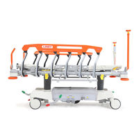
LINET Sprint 200 Instructions For Use Manual (136 pages)
Emergency Stretcher
Brand:
LINET
| Category:
Medical Equipment
| Size: 36.74 MB
Table of Contents
Table of Contents
4
Symbols and Definitions
8
Warning Notices
8
Types of Warning Notices
8
Structure of Warning Notices
8
Instructions
8
Lists
8
Symbols on the Package
9
Symbols on the Stretcher
10
Scales Indentification Label (Only Sprint 200 with Scales)
14
Fig. Example of Scales LW20 Label
14
Fig. Warning, Read Instructions for Use
14
Fig. Battery Activation Instructions
15
Symbols on the Mattress
16
Serial Label with UDI
18
Sprint 200
18
Fig. Position of Serial Label on the Sprint 200
18
Acoustic Signalisation (Only Sprint 200 with Scales or with I-Drive Power)
19
Definitions
19
Abbreviations
20
Safety Instructions
21
Intended Use of the Sprint 200 Without Scales
24
User Population
24
Contraindications
24
Operator
24
Intended Use of the Sprint 200 with Scales
25
User Population
25
Contraindications
25
Operator
25
Intended Use of the Sprint 200 Mattresses
26
User Population
26
Contraindications
26
Operator
26
Product Description
27
Hierarchy of Product Variants
27
Sprint 200 with 4-PART MATTRESS SUPPORT PLATFORM
28
Fig. Stretcher Overview (Sprint 200 with 4-Part Mattress Support Platform)
28
Sprint 200 with 2-PART MATTRESS SUPPORT PLATFORM
29
Fig. Stretcher Overview (Sprint 200 with 2-Part Mattress Support Platform)
29
Technical Specification
30
Identification of Applied Parts (Type B)
30
Mechanical Specifications (Sprint 200)
30
Electrical Specifications (Only Sprint 200 with Scales or with I-Drive Power)
32
Environment Conditions of the Sprint 200
33
Electromagnetic Compatibility (Only Sprint 200 with Scales or with I-Drive Power)
34
Manufacturer Instructions - Electromagnetic Emissions
34
Manufacturer Instructions - Electromagnetic Susceptibility
35
Use and Storage Conditions
36
Scope of Delivery and Product Variants
36
Delivery
36
Scope of Delivery
36
Sprint 200 Variants
37
Putting into Service
38
Mattress Support Platform
39
Fig. 4-Part Mattress Support Platform
39
Fig. 2-Part Mattress Support Platform
39
Removal of the Plastic Mattress Support Platform Covers
40
Fig. Instructions to Remove the Plastic Mattress Support Platform Covers
40
Insertion of the Plastic Mattress Support Platform Covers
41
Fig. Instructions to Insert the Plastic Mattress Support Platform Covers
41
Patient Restraint Points
42
Fig. Eight Patient Restraint Points (4-Part Mattress Support Platform)
42
Potential Interconnection (Optional)
43
Before Use
43
Fig. Potential Equalisation - Male (Head End, Bottom View)
43
Fig. Potential Equalisation Connector - Female
43
Transport
44
Transport Position
44
Firmware (Only Sprint 200 with Scales or with I-Drive Power)
45
Power Supply Cord (Only Sprint 200 with Scales or with I-Drive Power)
45
Fig. Power Supply Cord on the Head End of the Sprint 200 with Scales or with I-Drive Power
46
Fig. Hook for Hanging Power Supply Cord
46
Connection of the Power Supply Cord
47
Fig. Power Supply Cord Leading from the Undercarriage Cover and Wound Around the Accessory Rail
47
Indication of the Stretcher Connected to the Mains (Only Sprint 200 with Scales)
48
Batteries (Only Sprint 200 with Scales)
49
Batteries of the Scales System
49
Fig. Position of the Battery Box under the Seat Section of Sprint 200 with Scales
49
Battery Activation
50
Fig. Battery Box with Battery Isolating Foil under the Seat Section (Bottom View)
50
Battery Capacity Status Indicators
51
Pop-Up Windows Connected with Battery Capacity Status
51
Change of the 4 Batteries in Battery Box
52
Fig. Tipping the Battery Box Holder out (Bottom View)
52
Fig. Fixation of the Battery Box under the Seat Section (View from Foot End)
52
Fig. Battery Box with Cover Fixed with 4 Screws
53
Fig. Opened Battery Box with 4 Batteries
53
Batteries (Only Sprint 200 with I-Drive Power)
54
Manipulation
54
Collapsible Siderails
55
Siderail Description
56
Fig. Manipulation with Collapsible Siderail
56
Fig. Positions of both Siderail Release Levers When the Siderail Is Locked
57
Fig. Positions of both Siderail Release Levers When the Siderail Is Unlocked
57
Fig. Release of the Siderail at Head End and Foot End
58
Castor Control
59
Fig. Three Pedal Positions (Green Drive Pedal)
59
Braked Stretcher
60
Forward Movement (Steering)
60
Fig. Positions of Brake Pedals
60
Fig. Positions of Drive Pedals
60
Unrestricted Movement
61
Stretcher Positioning
61
Backrest
61
Fig. Manipulation with Backrest Release Handle
62
Fig. Positions of Backrest Release Handles
62
Thighrest (Only 4-Part Mattress Support Platform)
63
Fig. Position of Thighrest Latch
64
Calfrest (Only 4-Part Mattress Support Platform)
65
Fig. Calfrest Positioning
66
Fig. Catch in the Ratchet-Bar
66
Lifting
67
Fig. Positions of Lifting Pedals
67
Lowering
68
Fig. Positions of Head End Lowering Pedals and Foot End Lowering Pedals
68
Fig. Positions of Head End Lowering Pedals
68
Trendelenburg Position
69
Fig. Position of Head End Trendelenburg Pedal (Optional)
70
Anti-Trendelenburg Tilt
71
Fig. Positions of Foot End Lowering Pedals
71
Cardiac Chair Position (Only 4-Part Mattress Support Platform)
72
Emergency Backrest Release
73
The 2-Part Mattress Support Platform
73
Fig. Preparation for Cardiopulmonary Resuscitation (2-Part Mattress Support Platform)
73
The 4-Part Mattress Support Platform
74
Ergoframe
74
Fig. Preparation for Cardiopulmonary Resuscitation (4-Part Mattress Support Platform)
74
Scales Control (Only Sprint 200 with Scales)
75
Preparation
75
Fig. Scales and Bed Exit Alarm Monitoring Control Panel (Keyboard and Display)
75
Displaying
76
Discrete Mode
76
Fig. Display Description (Scales)
76
Fig. Discrete Mode
76
Taring
77
Stretcher Overload
78
Stretcher Underload
78
Weighing in Tilt
78
Calibration of the Zero
78
Fig. Sprint 200 with Scales Is Overloaded (Pop-Up)
78
Pop-Up Windows Connected with Scales Control
79
Basic Technical Parameters of the LW20 Scales System
80
Bed Exit Alarm Monitoring (Only Sprint 200 with Scales)
81
Fig. Scales and Bed Exit Alarm Monitoring Control Panel (Keyboard and Display)
81
Preparation
82
Displaying
82
Fig. Display Description (Bed Exit Alarm Monitoring)
82
Activation
83
Monitored Zone
83
Pause
83
Fig. Bed Exit Alarm Monitoring Button with 2 Green Indicators above
83
Bed Exit Alarm
84
Deactivation
84
Fig. Visual Signalisation of the Bed Exit Alarm on the Display (Yellow Field and Black Symbols)
84
Fig. Two Pictures Alternating During Triggered Bed Exit Alarm
84
Pop-Up Windows Connected with Bed Exit Alarm Monitoring
85
Settings Menu
86
Fig. Settings Menu
86
Fig. Verification Screen
86
Fig. Software and Hardware Versions Screen
86
Fig. Settings Menu (TIME and DATE)
86
Time and Date Settings
87
Fig. TIME and DATE Menu
87
Time and Date Format Settings
88
Fig. Settings Menu (TIME DATE SETTING)
88
Fig. TIME DATE SETTING Menu
88
Basic Technical Parameters of the Bed Exit Alarm Monitoring
89
Equipment
90
Accessory Rail with Plastic Hooks
90
Fig. Accessory Rail with Plastic Hooks (on Side)
90
Fig. Accessory Rail with Plastic Hooks (at Head End)
90
DIN Rail
91
Urinary Bag Holders
91
Fig. DIN Rail (on Side)
91
Fig. Urinary Bag Holder (on Side)
91
Undercarriage Cover
92
Fig. Storage Space (Undercarriage Cover of the Sprint 200 with I-Drive Power)
92
Fig. Storage Space (Undercarriage Cover of the Sprint 200 Without I-Drive Power)
92
Straps for Oxygen Bottles
93
Fig. Fixation of an Oxygen Bottle on the Undercarriage Cover with Straps for Oxygen Bottles
93
Flexidrive (Sprung Retractable Fifth Castor)
94
Sprint 200 with Solido 3
94
Fig. Activation of Fifth Castor
94
IV&Drive (Infusion Stands/Pushing Handles)
95
Fig. Pair of Foldable Infusion Stands (Head End)
95
Fig. Control Ring and Hooks
96
Handles
97
Foldable Handles
97
Fig. Foldable Handles (Foot End)
97
Fixed Handles
98
Fig. Fixed Handles (at Head End and Foot End)
98
Fig. Fixed Handles (at Head End)
98
Angle Indicators
99
Fig. Angle Indicators
99
Mobi-Lift Handle
100
Fig. Mobi-Lift Handle
100
Fig. Mobi-Lift Handle Control
100
I-Drive Power
101
Safety Instruction for I-Drive Power
101
Specifications of Use
101
Manipulation
102
Fig. Position of the I-Drive Power Main Control Panel on the IV&Drive
102
Fig. I-Drive Power Control Panel
103
I-Drive Power Activation/Deactivation
104
Fig. Position of the I-Drive Power Mains Switch
104
Fig. I-Drive Power Mains Switch with Label
104
Powered Drive
105
Braking
105
Free Drive
105
Batteries
106
Fault Signalization
106
Light Indicators
106
Fig. Accumulator Charge Status
106
Technical Specifications
107
Electrical Specification
107
I-Drive Power Maintenance
107
Mattress
108
Anti-Slip Coating
108
Installation of Passive Mattress
109
Strap with Side Release Buckles
109
Mattresses Specifications
111
Sprint 200 with Standard Mattress Support Platform
111
Cleaning of Passive Mattress
113
General Guidance
113
Routine Cleaning and Disinfection
114
Complete Cleaning and Disinfection
114
Mattress Core
114
Accessories
115
Infusion Stand
116
Fig. Positions for Infusion Stand
116
Fig. Infusion Stand (at Head End and Foot End Corners)
116
Telescopic Infusion Stand
117
Fig. Positions for Telescopic Infusion Stand
117
Fig. Telescopic Infusion Stand (at Head End and Foot End Corners)
117
Chart Holder
118
Fig. Position for Chart Holder
118
Monitor Shelf
119
Fig. Monitor Shelf (at Foot End)
119
Fig. Instruction for Placement of the Monitor Shelf to the Head End and Foot End Corners
119
Paper Roll Holder
120
Fig. Paper Roll Holder with Two Nibs
120
Fig. Two Optional Holders of the Paper Roll Holder
120
Fig. Paper Roll Holder (Foot End)
121
Storage Box
122
Fig. Storage Box (under the Backrest)
122
Oxygen Bottle Holder
123
Fig. Two Positions of the Oxygen Bottle Holder at Head End
123
Fig. Two Positions of the Oxygen Bottle Holder (at Head End on the Left)
124
Cleaning and Disinfection
125
Cleaning (Sprint 200)
127
Cleaning before Changing Patients
127
Daily Cleaning
127
Complete Cleaning and Disinfection
128
Troubleshooting (Sprint 200 Without Scales and Without I-Drive Power)
128
Troubleshooting (Sprint 200 with Scales or with I-Drive Power)
129
Pop-Up Windows
130
Fault Codes
131
Maintenance (Sprint 200 Without Scales and Without I- -Drive Power)
132
Regular Maintenance
132
Spare Parts
132
Safety Technical Checks
132
Maintenance (Sprint 200 with Scales or with I-Drive Power)
133
Regular Maintenance
133
Spare Parts
133
Safety Technical Checks
133
Disposal (Sprint 200 Without Scales and Without I-Drive Power)
134
Environment Protection
134
Disposal
134
Within Europe
134
Outside Europe
134
Disposal (Sprint 200 with Scales or with I-Drive Power)
135
Environment Protection
135
Disposal
135
Within Europe
135
Outside Europe
135
Warranty
136
Standards and Regulations
136
Sprint 200
136
Manufacturer
136
Advertisement
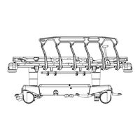
LINET Sprint 200 Instructions For Use And Technical Description (104 pages)
Emergency Stretcher without scales / with i-Drive Power and without i-Drive Power
Brand:
LINET
| Category:
Medical Equipment
| Size: 24.43 MB
Table of Contents
Table of Contents
3
Symbols and Definitions
5
Warning Notices
5
Types of Warning Notices
5
Structure of Warning Notices
5
Instructions
5
Lists
5
Symbols on the Package
6
Symbols on the Stretcher
7
Symbols on the Mattress
10
Serial Label with UDI
12
Sprint 200
12
Acoustic Signalisation (Only Sprint 200 with I-Drive Power)
13
Definitions
13
Abbreviations
14
Safety Instructions
15
Intended Use (Sprint 200 Without Scales)
18
User Population
18
Contraindications
18
Operator
18
Intended Use (Sprint 200 Mattresses)
19
User Population
19
Contraindications
19
Operator
19
Product Description
20
Hierarchy of Product Variants
20
Sprint 200 with 4-PART MATTRESS SUPPORT PLATFORM
21
Sprint 200 with 2-PART MATTRESS SUPPORT PLATFORM
22
Technical Specification
23
Identification of Applied Parts (Type B)
23
Mechanical Specifications (Sprint 200)
23
Electrical Specifications (Only Sprint 200 with I-Drive Power)
24
Environment Conditions (Sprint 200)
25
Electromagnetic Compatibility (Only Sprint 200 with I-Drive Power)
26
Manufacturer Instructions - Electromagnetic Emissions
26
Manufacturer Instructions - Electromagnetic Susceptibility
27
Use and Storage Conditions
28
Scope of Delivery and Product Variants
28
Delivery
28
Scope of Delivery
28
Sprint 200 Variants
29
Putting into Service
30
Mattress Support Platform
31
Removal of the Plastic Mattress Support Platform Covers
32
Insertion of the Plastic Mattress Support Platform Covers
33
Patient Restraint Points
34
Potential Interconnection (Optional)
35
Before Use
35
Transport
36
Transport Position
36
Firmware (Only Sprint 200 with I-Drive Power)
37
Power Supply Cord (Only Sprint 200 with I-Drive Power)
37
Connection of the Power Supply Cord
39
Batteries (Only Sprint 200 with I-Drive Power)
41
Manipulation
41
Collapsible Siderails
42
Siderail Description
42
Castor Control
44
Braked Stretcher
45
Forward Movement (Steering)
45
Unrestricted Movement
46
Stretcher Positioning
46
Backrest
46
Thighrest (Only 4-Part Mattress Support Platform)
48
Calfrest (Only 4-Part Mattress Support Platform)
50
Lifting
52
Lowering
53
Trendelenburg Position
54
Anti-Trendelenburg Tilt
56
Cardiac Chair Position (Only 4-Part Mattress Support Platform)
57
Emergency Backrest Release
58
The 2-Part Mattress Support Platform
58
The 4-Part Mattress Support Platform
59
Ergoframe
59
Equipment
60
Accessory Rail with Plastic Hooks
60
DIN Rail
61
Urinary Bag Holders
61
Undercarriage Cover
62
Straps for Oxygen Bottles
63
Flexidrive (Sprung Retractable Fifth Castor)
64
Sprint 200 with Solido 3
64
IV&Drive (Infusion Stands/Pushing Handles)
65
Handles
67
Foldable Handles
67
Fixed Handles
68
Angle Indicators
69
Mobi-Lift Handle
70
I-Drive Power
71
Safety Instruction for I-Drive Power
71
Specifications of Use
71
Manipulation
72
I-Drive Power Activation/Deactivation
74
Powered Drive
75
Braking
75
Free Drive
75
Batteries
76
Fault Signalization
76
Light Indicators
76
Technical Specifications
77
Electrical Specification
77
I-Drive Power Maintenance
77
Mattress
78
Anti-Slip Coating
78
Installation of Passive Mattress
79
Strap with Side Release Buckles
79
Mattresses Specifications
81
Sprint 200 with Standard Mattress Support Platform
81
Cleaning of Passive Mattress
83
General Guidance
83
Routine Cleaning and Disinfection
84
Complete Cleaning and Disinfection
84
Mattress Core
84
Accessories
85
Infusion Stand
86
Telescopic Infusion Stand
87
Chart Holder
88
Monitor Shelf
89
Paper Roll Holder
90
Storage Box
92
Oxygen Bottle Holder
93
Cleaning/Disinfection
95
Cleaning (Sprint 200)
97
Cleaning before Changing Patients
97
Daily Cleaning
97
Complete Cleaning and Disinfection
98
Troubleshooting (Sprint 200 Without Scales and Without I-Drive Power)
98
Troubleshooting (Sprint 200 with I-Drive Power)
99
Maintenance (Sprint 200 Without Scales and Without I- -Drive Power)
100
Regular Maintenance
100
Spare Parts
100
Safety Technical Checks
100
Maintenance (Sprint 200 with I-Drive Power)
101
Regular Maintenance
101
Spare Parts
101
Safety Technical Checks
101
Disposal (Sprint 200 Without Scales and Without I-Drive Power)
102
Environment Protection
102
Disposal
102
Within Europe
102
Outside Europe
102
Disposal (Sprint 200 with I-Drive Power)
103
Environment Protection
103
Disposal
103
Within Europe
103
Outside Europe
103
Warranty
104
Standards and Regulations
104
Sprint 200
104
Manufacturer
104
Advertisement
Related Products
LINET Eleganza 2
LINET EffectaCare 20 B
LINET EffectaCare 20 P
LINET Sprint 100
LINET 1VPKE20000010
LINET 1VPM000420200
LINET 1WIS0309060007
LINET Air2Care 10
LINET Air2Care 20
LINET Air2Care IN
LINET Categories
Medical Equipment
Indoor Furnishing
Baby & Toddler Furniture
Measuring Instruments
Personal Care Products
More LINET Manuals
Login
Sign In
OR
Sign in with Facebook
Sign in with Google
Upload manual
Upload from disk
Upload from URL