Sign In
Upload
Manuals
Brands
Linde Manuals
Forklifts
H 70 D-03
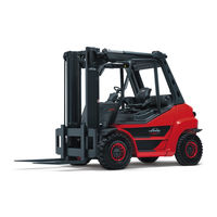
User Manuals: Linde H 70 D-03 Diesel Forklift
Manuals and User Guides for Linde H 70 D-03 Diesel Forklift. We have
1
Linde H 70 D-03 Diesel Forklift manual available for free PDF download: Service Training
Linde H 70 D-03 Service Training (282 pages)
IC-Engined Fork Truck, Type 353
Brand:
Linde
| Category:
Forklifts
| Size: 9.14 MB
Table of Contents
Table of Contents
3
IC-Engined Fork Truck H 50/60/70/80, Type
9
Engine Drive
9
Engine Model BF6M 1012 E
9
Engine Specifications
9
Explanation of the Engine Number
10
Changing and Tightening the Drivebelt
11
Adjusting Valve Clearance
12
Adjusting the Injection Valve
15
Checking the Compression Pressure
17
Cylinder Head
18
Adjusting the Begin of Delivery
20
Special Tools
24
Engine Model BF6M 2012
26
Overview of Engine Components
26
Engine Specifications
28
Explanation of the Engine Number
29
Replacement of V-Ripped Belt
30
Adjusting Valve Clearance
31
Checking and Adjusting Leak-Fuel-Free Injection Nozzles
32
Thermostat
38
Checking the Compression Pressure
40
Cylinder Head
41
Injection Pump
43
Adjusting the Begin of Delivery
43
Replacement of the Injection Pump
45
Heater Flange
51
Special Tools
54
Transmission
59
Hydrostatic Transmission
60
Schematic Diagram of the Drive
61
Transmission Specifications
62
Hydraulic Circuit Diagram
64
Operation of the Hydrostatic Transmission
78
Travel Control Unit P
78
Operation of Control Valve Block N = Power Limiter
81
Braking
82
Auxiliary Brake
82
Lock-Out Logic - Reversing Lock
84
Flushing of the Circuit and Housing
86
Hydraulic Remote Control
88
Adjustments
89
Hydraulic Neutral Position
89
Primary Adjustment of Start of Control
89
Mechanical Limitation of the Swashplate Angle
89
Hydraulic Remote Control HPV
90
Reversal Lock (Logic Lock Out)
92
Reducing the Truck Speed
92
Wheel Drive
93
Reduction Gearbox with Disc Brake (GR 80 -02/-03/-04)
94
Servicing the Reduction Gearbox (GR 80 -02/-03/-04)
96
Disc Brake Repairs
97
Reduction Gearbox GR 80 -06 with Multiple Disc Brake
98
Repair on the Reducing Gear GR
99
Troubleshooting
106
Connecting Diagram for Troubleshooting
106
Tools and Aids for Measurements
108
Explanations to Troubleshooting
110
Hydraulic Speed Control for the Engine
111
Functional Test
111
Troubleshooting
111
Hydraulic Braking System
116
Functional Test
116
Troubleshooting
116
Pressure Equality and Start of Control
119
Functional Test
119
Troubleshooting
119
Hydrostatic Travel Drive
123
Test and Adjustment Instructions for Hydraulic Primary and Secondary Control
135
Q Max
136
Of Variable Displacement Pump BPV
136
Qmax
138
Of Hydraulic Motors Hmv 105
138
Qmin
139
Of Hydraulic Motors Hmv 105
139
Chassis
141
Overhead Guard - Torsion Mounting
142
Work on the Overhead Guard
143
Steering System
145
Power Steering Circuit Diagram
146
Series 304 Steering Axle
148
Description
148
Steering Axle Removal
149
Steering Axle Installation
150
Steering Axle Repairs
150
Renewing the Wheel Bearings
151
Steering Knuckle Removal and Installation
152
Steering Cylinder Removal and Installation
154
Replacing the Steering Cylinder Seals
156
Steering Stop Adjustment
157
Controls
159
Accelerator and Brake Pedal Adjustment
160
Speed Control
163
Speed Control up to 10/95
163
Speed Control from 11/95
165
Medium Wheel Speed
166
Start of Drive Wheel Rotation
167
Brake Shaft Stop Screws
168
Symmetry of the Travel Control
169
Drive Wheel Start of Rotation
169
Engine Speed Increase
170
Pressure Difference Δp
171
Modification of Engine Acceleration
172
Electrical System
173
Wiring Diagram
174
Wiring Diagram for Options
178
Wiring Diagram
178
Wiring Diagram for Options
185
Wiring Diagram, 353 -03 Diesel
189
Wiring Diagram for Options
193
Electrical System Circuit Diagram, Type 353 -03 LPG
197
Wiring Diagram for Options
201
Central Electrical System
206
Central Electrics of Series
208
Relay and Fuses of 353 -03 Diesel
208
Relay and Fuses of 353 -03 LPG
210
Relay and Fuses for 353 -03 Particulate Trap
212
Working Hydraulics
213
Working Hydraulics Circuit Diagram
214
Explanation of the Working Hydraulics
215
Tilt Cylinder
216
Tilt Cylinder Removal, Installation, Adjustment, Sealing
217
Mast
221
Mast Removal
222
Lift Cylinder Removal, Installation
223
Sealing the Lift Cylinder
224
LP Gas Model H 50/60/70/0, Type
227
Drive Engine
227
Technical Data on Engine
227
Technical Data on Engine up to 12/2004
227
Technical Data on Engine from 01/2005
228
Note on the Engine Number
229
Changing and Tensing V-Belt
230
Checking and Setting Valve Clearance
231
Removing and Installing the Cylinder Head
232
Electrical System
235
Electronic Ignition System
235
Electronic Ignition System up to 12/2004
235
Electronic Ignition System from 01/2005
240
4.9.2.1.2.1 Mechanical Ignition Timing
245
Electronic Engine-Speed Control
249
Electrical System Circuit Diagram up to 12/2004
252
Electrical System Circuit Diagram from 01/2005
256
Propellant Gas System
259
Diagram
259
Functional Description of the Propellant Gas System
260
Inspections and Adjustments
268
Ignition System
268
Installation of the Engine Speed Control System
272
Inspection of the Engine Speed Control System
274
Adjustment of the Propellant Gas Mixers
279
Advertisement
Advertisement
Related Products
Linde H 70 D-02
Linde H 70 T-02
Linde H 70 T-03
Linde H 50 T
Linde H 60 T
Linde H 70 T
Linde H 80 T
Linde H 50 D-02
Linde H 60 D-02
Linde H 50 T-02
Linde Categories
Welding System
Forklifts
Trucks
Controller
Display Case
More Linde Manuals
Login
Sign In
OR
Sign in with Facebook
Sign in with Google
Upload manual
Upload from disk
Upload from URL