Sign In
Upload
Manuals
Brands
Lexmark Manuals
Printer
CS748de
Lexmark CS748de Manuals
Manuals and User Guides for Lexmark CS748de. We have
2
Lexmark CS748de manuals available for free PDF download: Service Manual, Brochure & Specs
Lexmark CS748de Service Manual (504 pages)
Brand:
Lexmark
| Category:
Printer
| Size: 20.16 MB
Table of Contents
Table of Contents
3
Notices and Safety Information
9
Laser Notice
9
Aviso sobre O Laser
10
Lithium Warning
15
Safety Information
15
Preface
18
Change History
18
Conventions
18
Navigation Buttons
19
General Information
21
Models
21
Options
21
Media Options
22
Memory Options
23
Printer Specifications
24
Dimensions
24
Clearances
25
Memory
25
Expansion Opportunities
26
Resolution
26
Data Streams
26
Environment Specifications
26
Electrical and Power Specifications
27
Acoustic Specifications
28
Media Specifications
29
Input and Output Capacities
31
Input and Output Sizes and Types
32
Paper Guidelines
34
Tools Required for Service
36
Acronyms
37
Diagnostic Information
39
Start
39
Operator Panel and Menus
40
C746X Operator Panel
40
C746X Buttons and Light Descriptions
40
C748X Operator Panel
41
C748X Buttons and Light Descriptions
41
Administrative Menus
46
Power-On Self Test (POST) Sequence
47
Symptom Tables
47
Printer Symptom Table
47
Print Quality Symptom Table
48
User Status and Attendance Messages
49
Error Codes and Messages
59
Service Checks
83
XX-Cartridge Errors Service Check
83
XX-Mirror Motor Service Check
83
XX, 112.XX, 113.XX, and 114.XX-Printhead Error Service Check
84
XX-Fuser Error Service Check
85
XX, 920.02-Autocomp (Tray 1) Motor Error Service Check
87
XX, 906.01-906.04-Motor (Fuser) Error Service Check
87
XX-Motor (EP Drive Assembly Top Cartridge 1 Motor) Error Service Check
89
XX-Motor (EP Drive Assembly Middle Cartridge) Error Service Check
90
XX-Motor (EP Drive Assembly Bottom Cartridge) Error Service Check
92
XX, 148.XX-Motor (Mpf/Duplex) Error Service Check
93
XX, 906.05-906.08, 920.01-POST (Power-On Self Test) Aligner Error Service Check
95
XX-Cam Motor Error Service Check
96
XX-COD (Color on Demand) Motor Service Check
98
XX, 161.XX-Motor Error (Option Tray 2) Service Check
98
Next
98
XX, 163.XX-Motor Error (Option Tray 3) Service Check
99
XX, 165.XX-Motor Error (Option Tray 4) Service Check
100
XX, 167.XX-Motor Error (Option Tray 5) Service Check
101
Go Back
101
XX-Motor (HCIT Elevator) Error Service Check
103
250.03-Paper Jam Error Service Check
103
201.08, 201.31-Paper Jam Error Service Check
104
Paper Jam Error Service Check
107
230.05-Paper Jam Error Service Check
109
Paper Jam Service Check
110
242.11-Paper Jam Service Check
111
Paper Jam Service Check
112
Paper Jam Service Check
113
Paper Jam Service Check
114
Paper Jam Service Check
115
Paper Jam Service Check
116
Paper Jam Service Check
117
243.11-Paper Jam Service Check
118
Paper Jam Service Check
119
Paper Jam Service Check
120
Paper Jam Service Check
121
Paper Jam Service Check
122
Paper Jam Service Check
123
244.11-Paper Jam Service Check
124
Paper Jam Service Check
125
Paper Jam Service Check
126
Paper Jam Service Check
127
Paper Jam Service Check
128
245.11-Paper Jam Service Check
129
Paper Jam Service Check
130
Paper Jam Service Check
131
Paper Jam Service Check
132
Steps before Starting the 9Yy Service Checks
132
900.99 (Except 900.05)-System Software Error Service Check
133
Transfer Module Error Service Check
136
Engine Software Error, NVRAM MGR Problem Service Check
136
920.25-Transfer Module Missing or Not Connected Service Check
137
POST (Power-On Self Test) Fuser Motor Not Connected Error Service Check
138
POST (Power-On Self Test) Printhead Motor Not Connected Error Service Check
139
Input Sensor Service Check
139
POST (Power-On Self Test)-Narrow Media Sensor Error Service Check
140
Exit Sensor Service Check
141
POST (Power-On Self Test)-Four Toner Sensors Not Connected Error Service Check
142
POST-Three Toner Sensors Not Connected Error Service Check
143
POST (Power-On Self Test)-Two Toner Sensors Not Connected Error Service Check
144
POST (Power-On Self Test)-One Toner Sensor Not Connected Error Service Check
146
POST (Power-On Self Test) Cartridge Motor 1 Not Connected Error Service Check
147
POST (Power-On Self Test)-Cartridge Motor 2 Not Connected Error Service Check
148
POST (Power-On Self Test)-Bad Printhead NVRAM Data Error Service Check
149
Next
149
POST (Power-On Self Test)-Output bin Cable Not Connected Error Service Check
150
POST (Power-On Self Test)-Cartridge Motor 3 Not Connected Error Service Check
151
POST (Power-On Self Test)-24 V Power Supply Failure Error Service Check
153
POST (Power-On Self Test)-Duplex Motor Not Connected Error Service Check
154
920.28, 920.29-POST (Power on Self Test) Option Tray Error Service Check
155
MPF Paper Present Sensor Not Connected Service Check
155
925.03, 925.05-Fan Error Service Check
155
925.04, 925.06-Cartridge Cooling Fan Error Service Check
156
XX, 947.XX-Transfer Roll Error Service Check
157
950.29-EPROM Mismatch Failure
159
XX-System Board Failure Service Check
160
Interlock Switch Service Check
161
V Interlock Switch Service Check
162
Bubble Sensor Service Check
163
Dead Printer Service Check
165
Networking Service Check
165
Operator Panel Service Check
168
Print Quality Service Check
169
Tray 1 Missing Service Check
177
Tray Linking Service Check
178
Diagnostic Aids
179
Accessing Test and Diagnostic Procedure Menus
179
Diagnostics Menu
179
Diagnostics Menu Structure
180
Available Tests
180
Registration
183
Alignment
186
Motor Tests
188
Print Tests
190
Hardware Tests
192
Duplex Tests
194
Sensor Test
197
Printhead Tests
198
Device Tests
198
Printer Setup
200
EP Setup
202
Reports
203
Event Log
203
Exit Diagnostics
204
Configuration Menu (CONFIG MENU)
205
Available Tests
205
Reset Fuser Cnt
206
Color Lock out
206
Print Quality
206
Reports
207
Color Trapping
207
Tray Insert Msg
207
Panel Menus
207
PPDS Emulation
208
Download Emuls
208
Demo Mode
208
Factory Defaults
208
Energy Conserve
208
Automatic Color Adjust
209
Auto Align Adj
209
Color Adj State
209
Enforce Color Order
209
Color Alignment
209
Motor Calibration
210
Paper Prompts
210
Envelope Prompts
210
Action for Prompts
210
Jobs on Disk
210
Disk Encryption
211
Wipe Disk
211
Wipe All Settings
211
Duplex Gloss
212
Font Sharpening
212
Require Standby
212
UI Automation
212
Key Repeat Initial Delay
212
Key Repeat Rate
212
Clear Custom Status
212
USB Speed
212
Automatically Display Error Screens
213
Exit Config
213
Front Cover Locked in Place
214
Printhead Verification
217
Paper Jams
220
Error Jam Locations
220
Clearing Jams
221
Paper Jam
224
Theory of Operation
229
Paper Path
229
Electrophotographic (EP) Process
241
Electrical Interlock
251
Repair Information
253
Safety Information
253
Data Security Notice
253
Handling ESD-Sensitive Parts
254
Handing the Photoconductor Unit
254
Transportation/Storage
254
Handling
254
Parts Not to be Touched
254
Screw and Retainer Identification Table
255
Adjustments
260
Printhead Alignment
260
Printer Removal Procedures
280
Precautions to Take before Maintenance Work
280
Cover Removals
281
Front Access Cover Assembly Removal
281
Left Cover Removal
283
Operator Panel Assembly Removal (C746)
286
Operator Panel Assembly Removal (C748)
289
Operator Panel Bezel Removal
293
Operator Panel Buttons Removal (C746)
293
Operator Panel Buttons Removal (C748)
295
Output bin Extension Cover Removal
297
Paper Tray Dust Cover Removal
298
Rear Frame Cover Removal
299
Rear Left Cover Removal
300
Rear Right Cover Removal
301
Rear Upper Cover Removal
302
Right Cover Removal
303
Top Access Cover Assembly Removal
306
Top Cover Assembly Removal
310
Printer Removals
313
Interlock Switch Cable Removal
313
Go Back
313
Interlock Switch Removal
315
Bin Full Sensor Flag Removal
317
Bin Full Sensor Removal
317
Cartridge Cooling Fan Removal
318
Cartridge Guide Wheel Removal
319
Cartridge Motor 1/Fuser Cable Removal
326
Cartridge Motor 2/3 Cable Removal
329
Color on Demand Assembly Removal
330
Contact Springs Kit Removal
335
Cooling Fan Removal
345
Cooling Fan Filter Removal
346
Duplex Reference Edge Guide Assembly Removal
347
Electrophotographic (EP) Drive Assembly Removal
350
Front Door Assembly Removal
360
Front Door Assembly Front Cable (Left) Removal
363
Front Door Assembly Front Cable (Right) Removal
367
Fuser Removal
370
Fuser AC Cable Removal
372
Fuser DC Cable Removal
373
Hard Drive Assembly Removal
374
High-Voltage Power Supply (HVPS) Removal
375
High-Voltage Power Supply (HVPS) Cable Removal
377
Left Bell Crank Assembly Removal
378
Low-Voltage Power Supply (LVPS) Removal
379
Motor Driver Card Removal
381
Motor Driver Cable Removal
382
Multipurpose Feeder (Mpf)/Duplex Gear and Housing Removal
383
Multipurpose Feeder (Mpf)/Duplex Motor Assembly Removal
385
Multipurpose Feeder (Mpf)/Duplex Motor Cable Removal
388
Multipurpose Feeder (MPF) Paper Present Sensor
389
MPF Pick Removal
391
Operator Panel Cable Removal
392
Operator Panel Ground Cable Removal
393
Operator Panel USB Connector Cable Removal
394
Option Cable Removal
395
Paper Pick Mechanism Assembly Removal
397
Photoconductor Unit Removal
402
Pick Arm Roll Removal and Replacement
403
Printer Pad Removal
404
Printhead Removal, Installation, and Adjustment
405
Right Bell Crank Assembly Removal
414
Speaker Removal
415
System Board Removal
415
System Board Support Shield Removal
420
Toner Level Sensor Removal
423
Top Cover Camshaft Assembly Removal
425
Transfer Module Removal
431
Transport Cable Removal
433
Transport Motor Cable Removal
435
Waste Toner Assembly Removal
436
Waste Toner HV Contact Assembly Removal
437
Wireless Network Antenna Removal
450
Wireless Network Card Removal
451
Option Removals
453
HCIT Front Tray Cover Removal
454
HCIT Rear Cover Removal
455
HCIT Right Cover Removal
456
HCIT Left Cover Removal
457
Feed with Bushing Roller Removal
458
HCIT Controller Board Assembly Removal
459
HCIT Drawer Slide Assembly Removal
460
HCIT Elevator Motor with Sensor Removal
460
HCIT Pick Arm Roll Removal
462
HCIT Slide Assembly with Spring Removal
463
Photointerrupter Sensor with Cable Assembly Removal
465
Top Plate Assembly Removal
466
Connector Locations
469
Locations
469
Connectors
470
System Board Diagram
470
Preventive Maintenance
473
Safety Inspection Guide
473
Lubrication Specifications
473
Maintaining the Printer
473
Cleaning the Exterior of the Printer
473
Cleaning the Printhead Lenses
474
Moving the Printer
474
Parts Catalog
475
How to Use this Parts Catalog
475
Assembly 1: Covers (C746)
476
Assembly 2: Covers (C748)
478
Assembly 3: Front
480
Assembly 4: Right
482
Assembly 5: Rear
484
Assembly 6: Left
486
Assembly 7: Top
488
Assembly 8: Cable Parts Packet
489
Assembly 9: Optional 550-Sheet Media Drawer and Tray
490
Assembly 10: Optional Special Media Tray Assembly
491
Assembly 11: Optional High-Capacity Input Option (HCIT)
492
Assembly 12: Options and Features
494
Index
495
Part Number Index
501
Advertisement
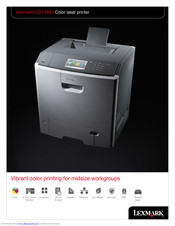
Lexmark CS748de Brochure & Specs (8 pages)
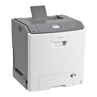
Color laser printer
Brand:
Lexmark
| Category:
All in One Printer
| Size: 3.33 MB
Table of Contents
Additional Solutions
5
Key Features
6
Ordering Information
7
Product Specifications
8
Advertisement
Related Products
Lexmark Cs736dn - Laserpr Col Sku Specs Tbd
Lexmark CS720 Series
Lexmark CS725
Lexmark CS725R
Lexmark CS727
Lexmark CS720de
Lexmark CS720dte
Lexmark CS730
Lexmark CS735
Lexmark CS735de
Lexmark Categories
Printer
All in One Printer
Printer Accessories
Software
Print Server
More Lexmark Manuals
Login
Sign In
OR
Sign in with Facebook
Sign in with Google
Upload manual
Upload from disk
Upload from URL