Sign In
Upload
Manuals
Brands
Lennox Manuals
Air Conditioner
XP25-036-230-01
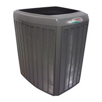
Lennox XP25-036-230-01 Heat Pump Manuals
Manuals and User Guides for Lennox XP25-036-230-01 Heat Pump. We have
1
Lennox XP25-036-230-01 Heat Pump manual available for free PDF download: Installation And Service Procedure
Lennox XP25-036-230-01 Installation And Service Procedure (90 pages)
Dave Lennox Signature Collection XP25 Series Units
Brand:
Lennox
| Category:
Air Conditioner
| Size: 3.6 MB
Table of Contents
Table of Contents
1
Overview
2
Model Number Identification
2
Typical Serial Number Identification
2
Specifications
2
Electrical Data
3
Unit Dimensions
4
Typical Unit Parts Arrangement
5
Control Panel Components
5
Plumbing (Component Locations and Specifications)
6
General Information
7
Torque Requirements
7
Using Manifold Gauge Set
7
Operating Service Valves
7
Operating Angle-Type Service Valve
8
Operating Ball-Type Service Valve
8
To Access Service Port
8
Reinstall Stem Cap
8
Installation
9
Unit Placement
9
Placing Unit on Slab
9
Elevating the Unit
9
Stabilizing Unit on Uneven Surfaces
10
Wind Barrier (Rooftop or Ground Application) View
10
Outside Unit Placement
11
Slab Mounting at Ground Level
11
Elevated Slab Mounting Using Feet Extenders
11
Slab Side Mounting
11
Removing and Installing Panels
12
Louvered Panel Removal
12
Louvered Panel Installation
12
New or Replacement Line Set
13
Refrigerant Line Set
13
Cooling System (HFC-410A)
14
Standard Refrigerant Line Set — up to 50 Linear Feet
14
XP25 Piping Guidelines
14
Liquid Line Diameter Selection Table
14
Line Set Installation
15
Brazing Connections
16
Brazing Procedures
17
Piping Panel Removal and Line Set Preparation
17
Cap and Core Removal
17
Wrap Service Valves
18
Flow Nitrogen
18
Baze Line Set
18
Preparation for Next Step
18
Flushing the System
19
Fypical Existing Fixed Orifice Removal Procedure
19
Typical Existing Expansion Valve Removal Procedure
19
Connecting Gauges and Equipment for Flushing Procedure
19
Flushing Line Set and Indoor Coil
20
Typical New Check Expansion Valve Installation Procedure
20
Sensing Bulb Installation
20
Equalizer Line Installation
20
Leak Testing the System
21
Installing Isolation Grommets
21
System Leak Test
22
Line Set and Indoor Coil
22
Connect Gauge Set
22
Evacuating the System
23
Electrical
24
Size Circuit and Install Disconnect Switch
24
Install Thermostat
24
Load Shedding
24
Route Control Wires
25
Route High Voltage and Ground Wires
25
Outdoor Unit Control Diagram
26
Outdoor Control Terminal Designations and Input/Outputs
27
Servicing Units Delivered Void of Charge
29
Unit Start-Up
29
System Operation and Service
30
7-Segment Alert and System Status Codes
30
Resetting Alert Codes
30
Outdoor Control 7-Segment Display Alert Codes and Inverter LED Flash Codes
30
Outdoor Control 7-Segment Unit Status Displays
36
Push-Button Operation
38
Unit Selection Code for Outdoor Control
38
Idle Mode — Decimal Flashes at 1 Hertz > 0.5 Second ON, 0.5 Second OFF. Idle Mode Is When the System Is Energized but no Demand
38
Field Test Mode Operation
39
Pump down Mode Operation
39
Forced Defrost Mode
39
Pump down Jumper
39
Field Test, Diagnostic Recall and Program Menu Options
40
Normal Operation Character Display String
40
Typical 7-Segment Demand Display String
40
Enabling Liquid Line Temperature Information
41
Configuring Unit Selection Code
42
Reconfiguring Outdoor Control Using Icomfort Wi-Fi Thermostat
43
Diagnostic Information
43
Installer Test
43
Defrost Function
43
Compressor Short-Cycling Delay
44
Heat Pump Cooling Operational Range
44
Heat Pump Heating Operational Range
44
Outdoor Temperature Operational Range
44
Maintenance
45
Sunsource Home Energy System
45
Locations with Possibility of Heavy Snow or Freezing Rain Accumulation
45
Snow Guard Top Cover View — X8782
45
Typical Unit Wiring (XP25-024 and -036)
46
Unit Wiring Diagrams
46
Typical Unit Wiring (XP25-048 and -060)
47
Load Shedding Feature Wiring Diagram
48
Factory Wiring Diagrams
49
Typical Factory Wiring (XP25-024 and -036)
49
Typical Factory Wiring (XP25-048 and -060)
50
Unit Sequence of Operations
51
24 VAC Power-Up or Outdoor Reset
51
Heat Pump Mode
52
Transition to Auxiliary Heat
53
Auxiliary Heat
54
Defrost Calibration and Defrost Mode Sequence of Operations (All Versions)
55
Component Testing
56
High and Low Pressure Switch Operation, Checkout and Status / Error Codes
56
Verifying High Pressure and Low Pressure Switch Operation
56
Low Pressure Switch (S87) Sequence of Operation (All Versions)
57
High Pressure Switch (S4) Sequence of Operation (All Versions)
58
High and Low Pressure Switch Errors
59
Outdoor Control 7-Segment Display Alert Codes - High and Low Pressure Switches
59
Reversing Valve Operation, Checkout and Status / Error Codes
60
Reversing Valve (L1)
60
Reversing Valve Checkout
60
Typical Reversing Valve Components and Operation
61
Compressor Operation, Checkout and Status / Error Codes
62
Outdoor Control 7-Segment Display Alert Codes - Compressor
63
Crankcase Heater, Checkout and Status / Error Codes
64
Belly-Band Crankcase Heater Thermostat
64
Checking Belly-Band Crankcase Heater
64
Checking Crankcase Heater Thermostat
65
Compressor Sound Cover
65
Charge Compensator (XP25-024-230-XX and XP25-048-230-XX Only)
66
Discharge Muffler (Heat Pumps Only)
66
Liquid Line Bi-Flow Filter Drier (Heat Pumps Only)
67
Check Expansion Valve (Heat Pumps Only)
68
Plumbing (Component Locations and Specifications) - Diagram
69
Top Cap Switch Operation, Checkout and Status / Error Codes
70
Outdoor Control 7-Segment Display Alert Codes - Top Cap Switch
70
Reactor Operations, Checkout and Status / Error Codes
71
XC/XP 25-024 and -036 Reactor
71
XC/XP 25-048 and -060 Reactor
71
Outdoor Fan Operation and Checkout
72
VAC Voltage Check
72
XP25 4- and 5-Ton Filter Board (EMC)
72
VAC Voltage Check - Diagram
73
VDC Voltage Check
74
Ferrites
74
Outdoor Control Operation, Checkout and Status / Error Codes
75
Outdoor Control 7-Segment Display Alert Codes - Outdoor Control Errors
76
Unit Sensor Operations, Checkout and Status / Error Codes
76
Coil Temperature Sensor (RT21)
76
Ambient Temperature Sensor (RT13), Liquid Line Temperature Sensor (RT36)
76
Temperature Sensor Specifications
77
Temperature Sensor Locations
77
Ambient, Coil and Liquid Line Sensors Temperature / Resistance Range
78
Variable-Capacity Inverter Control Operation, Checkout, Status / Error Codes
79
2- and 3-Ton Unit Inverter View
79
4- and 5-Ton Unit Inverter View
80
Outdoor Control 7-Segment Display Alert Codes, DC Inverter and Outdoor Control LED Flash Codes
80
Outdoor Control 7-Segment Display Alert Codes and Inverter LED Flash Codes - Table
80
Emergency 24VAC System Operation
84
Thermostat Communication Mode
84
System Refrigerant
85
Gauge Set Connections
85
Checking Indoor Airflow over Evaporator Coil Using Delta-T Chart
86
Using HFC-410A Weigh in Method
87
Using HFC-410A Subcooling Method — High Speed (High Capacity)
87
HFC-410A Temperature (Degrees F) - Pressure (Psig)
88
XP25 Charging Sticker
89
Advertisement
Advertisement
Related Products
Lennox XP25-024-230-01
Lennox XP25-048-230-01
Lennox XP25-060-230-01
Lennox XP21-036
Lennox XP21-024
Lennox XP21-060
Lennox XP21-048
Lennox XP14-018-230-07
Lennox XP14-036-230-02
Lennox XP14-036-230-08
Lennox Categories
Furnace
Air Conditioner
Heat Pump
Indoor Fireplace
Thermostat
More Lennox Manuals
Login
Sign In
OR
Sign in with Facebook
Sign in with Google
Upload manual
Upload from disk
Upload from URL