Sign In
Upload
Manuals
Brands
L-Acoustics Manuals
Speakers
MTD Series
User Manuals: L-Acoustics MTD Series Loudspeaker System
Manuals and User Guides for L-Acoustics MTD Series Loudspeaker System. We have
1
L-Acoustics MTD Series Loudspeaker System manual available for free PDF download: Operator's Manual
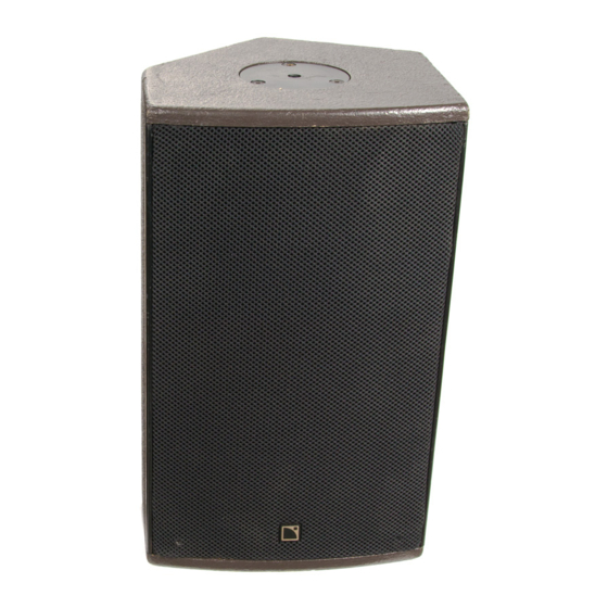
L-Acoustics MTD Series Operator's Manual (69 pages)
Brand:
L-Acoustics
| Category:
Speakers
| Size: 3.31 MB
Table of Contents
Foreword
2
Manual Organization
2
Table of Contents
4
List of Figures
5
List of Tables
6
Introduction
7
1 The Mtd System
8
Mtd System Components
8
Figure 1: MTD System Components
10
Figure 2: MTD LLC Controllers
12
Mtd Overview
13
Mtd108A SPECIFICATIONS
14
Figure 3: Mtd108A Passive 2-Way (8" LF + 1" HF) Coaxial Loudspeaker
14
Mtd112B SPECIFICATIONS
15
Figure 4: Mtd112B Passive 2-Way (12" LF + 1.4" HF) Coaxial Loudspeaker
15
Mtd115B SPECIFICATIONS
16
Figure 5: Mtd115B Active/Passive 2-Way (15" LF + 1.4" HF) Coaxial Loudspeaker
16
2 Powering Mtd
17
Figure 6: MLS Switches on the Rear Panel of L-ACOUSTICS La24A, La48A Amplifiers
17
POWERING Mtd108A
18
Table 1: Load and Power Ratings for Mtd108A
18
Table 2: Recommended Power Amplification and MLS Switch Settings for Mtd108A
18
Table 3: Recommended MLS Switch Settings for Powering Mtd108A
18
POWERING Mtd112B
19
Table 4: Load and Power Ratings for Mtd112B
19
Table 5: Recommended Power Amplification and MLS Switch Settings for Mtd112B
19
Table 6: Recommended MLS Switch Settings for Powering Mtd112B
19
POWERING Mtd115B (PASSIVE MODE)
20
Table 7: Load and Power Ratings for Mtd115B (Passive Mode)
20
Table 8: Recommended Power Amplification, MLS Switch Settings for Mtd115B (Passive Mode)
20
Table 9: Recommended MLS Switch Settings for Powering Mtd115B (Passive Mode)
20
POWERING Mtd115B (ACTIVE MODE)
21
Table 10: Load and Power Ratings for Mtd115B (Active Mode)
21
Table 11: Recommended Power Amplification and MLS Switch Settings for Mtd115B Low Section
21
Table 12: Recommended Power Amplification and MLS Switch Settings for Mtd115B High Section
22
Table 13: Recommended MLS Switch Settings for Powering Mtd115B (Active Mode)
22
Table 14: Output Power Ratings and MLS Switch Settings for L-ACOUSTICS Laa Amplifiers
23
Connectors and Cables
24
Table 15: Maximum Recommended Length for Damping Factor > 20
24
3 Processing Mtd
25
L-ACOUSTICS MTD108 Llca DESCRIPTION
25
L-ACOUSTICS LLC 112B-St DESCRIPTION
25
L-ACOUSTICS LLC 115B-St, Llc115B-2W DESCRIPTION
26
4 Mtd Configurations
27
Mtd108A FLOOR MONITOR SYSTEM
28
Figure 7A: Mtd108A Floor Monitor System Block Diagram
28
Figure 7B: Mtd108A Floor Monitor System Cabling Detail
28
Mtd108A FOH SYSTEM (MONO SUBS)
29
Figure 8A: Mtd108A FOH System Block Diagram (Mono Subwoofers)
29
Figure 8B: Mtd108A FOH System Cabling Detail (Mono Subwoofers)
29
Mtd108A FOH SYSTEM (STEREO SUBS)
30
Figure 9A: Mtd108A FOH System Block Diagram (Stereo Subwoofers)
30
Figure 9B: Mtd108A FOH System Cabling Detail (Stereo Subwoofers)
30
Mtd112B FLOOR MONITOR SYSTEM
31
Figure 10A: Mtd112B Floor Monitor System Block Diagram
31
Figure 10B: Mtd112B Floor Monitor System Cabling Detail
31
Mtd112B FOH SYSTEM (MONO SUB)
32
Figure 11A: Mtd112B FOH System Block Diagram (Mono Subwoofers)
32
Figure 11B: Mtd112B FOH System Cabling Detail (Mono Subwoofers)
32
Mtd112B FOH SYSTEM (STEREO SUBS)
33
Figure 12A: Mtd112B FOH System Block Diagram (Stereo Subwoofers)
33
Figure 12B: Mtd112B FOH System Cabling Detail (Stereo Subwoofers)
33
Mtd115B (PASSIVE) FLOOR MONITOR SYSTEM
34
Figure 13A: Mtd115B (Passive) Floor Monitor System Block Diagram
34
Figure 13B: Mtd115B (Passive) Floor Monitor System Cabling Detail
34
Mtd115B (PASSIVE) FOH SYSTEM (MONO SUB)
35
Figure 14A: Mtd115B (Passive) FOH System Block Diagram (Mono Subwoofers)
35
Figure 14B: Mtd115B (Passive) FOH System Cabling Detail (Mono Subwoofers)
35
Mtd115B (PASSIVE) FOH SYSTEM (STEREO SUBS)
36
Figure 15A: Mtd115B (Passive) FOH System Block Diagram (Stereo Subwoofers)
36
Figure 15B: Mtd112B (Passive) FOH System Cabling Detail (Stereo Subwoofers)
36
Mtd115B (ACTIVE) FLOOR MONITOR SYSTEM
37
Figure 16A: Mtd115B (Active) Floor Monitor System Block Diagram
37
Figure 16B: Mtd115B (Active) Floor Monitor System Cabling Detail
37
Mtd115B (ACTIVE) FOH SYSTEM (STEREO SB118 SUBS)
38
Figure 17A: Mtd115B (Active) FOH System Block Diagram (Mono Subwoofers)
38
Figure 17B: Mtd115B (Active) FOH System Cabling Detail (Mono Subwoofers)
38
Mtd115B (ACTIVE) FOH SYSTEM (STEREO SB218 SUBS)
39
Figure 18A: Mtd115B (Active) FOH System Block Diagram (Stereo Subwoofers)
39
Figure 18B: Mtd112B (Active) FOH System Cabling Detail (Stereo Subwoofers)
39
5 Sound Design
40
Applications
40
Aiming Mtd Enclosures
40
Arraying Mtd Enclosures
41
Figure 19: General Guidelines for Aiming MTD Enclosures
41
Figure 20: SPL Mappings at Octave Band Frequencies for a Single MTD Enclosure
41
Figure 21: SPL Mappings for Two MTD Enclosures with 0.5 Metre Spacing
42
Figure 22: SPL Mappings for Two MTD Enclosures with 3 Metre Spacing
42
Figure 23: General Guidelines for Arraying MTD Enclosures
43
Figure 24: SPL Mappings for Four MTD Enclosures with 0.5 Metre Spacing
43
Predicting Mtd Coverage
44
Distributed Sound Reinforcement
44
Overhead Distributed Systems
44
Delay Systems
44
Complementary Fill
45
Front-Of-House (Foh) Applications
46
Stage Monitoring
47
Table 16: Nominal Floor Monitor Distance (to Performer) and Separation Versus Performer Height
48
Using Mtd with Subwoofers
49
Figure 25: L-ACOUSTICS Subwoofer Continuous Unweighted SPL Comparison
49
Table 17: L-ACOUSTICS Subwoofer Specification Summary
49
Combining Mtd with Subwoofers
50
Ground Stacked Systems
50
Figure 26: Illustration of Subwoofer Time Alignment
51
Separate Flown Mtd with Ground Stacked Subwoofers
51
6 Installation Procedures
52
ETR8 U-BRACKET ATTACHMENT(Mtd108A)
52
Figure 27: ETR8 U-Bracket Installation Procedure
52
ETR1, ETR2 U-BRACKET ATTACHMENT (Mtd112B, Mtd115B)
53
Figure 28: ETR1, ETR2 U-Bracket Installation Procedure
53
OMNIMOUNT BRACKET ATTACHMENT (Mtd112B, Mtd115B)
54
Safety Rules
54
Figure 29: Omnimount Installation Procedure
54
7 Mtd System Operation
55
Recommended Maintenance Procedures
55
Spare Parts
56
8 Specifications
57
Mtd108A SPECIFICATIONS
57
Figure 30: Mtd108A Line Drawing
58
Figure 31: Mtd108A Plus ETR8 Line Drawings
59
Mtd108Llca SPECIFICATIONS
60
Mtd112B SPECIFICATIONS
61
Figure 32: Mtd112B Line Drawing
62
Figure 33: Mtd112B Plus ETR1 Line Drawings
63
Llc112B-St SPECIFICATIONS
64
Mtd115B SPECIFICATIONS
65
Figure 34: Mtd115B Line Drawing
66
Figure 35: Mtd115B Plus ETR2 Line Drawings
67
Llc115B-St, Llc115B-2W SPECIFICATIONS
68
Advertisement
Advertisement
Related Products
L-Acoustics MTD108a
L-Acoustics MTD112b
L-Acoustics MTD115b
L-Acoustics M-BARi
L-Acoustics MTD 112
L-Acoustics M-BUMPi
L-Acoustics 1003905.00
L-Acoustics A-U15i
L-Acoustics A10
L-Acoustics A15i Focus
L-Acoustics Categories
Speakers
Subwoofer
Enclosure
Racks & Stands
Speaker System
More L-Acoustics Manuals
Login
Sign In
OR
Sign in with Facebook
Sign in with Google
Upload manual
Upload from disk
Upload from URL