Sign In
Upload
Manuals
Brands
L'Acoustics Manuals
Stereo System
dV-DOSC
L'Acoustics dV-DOSC Manuals
Manuals and User Guides for L'Acoustics dV-DOSC. We have
2
L'Acoustics dV-DOSC manuals available for free PDF download: Operator's Manual
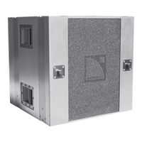
L-Acoustics dV-DOSC Operator's Manual (150 pages)
Brand:
L-Acoustics
| Category:
Speaker System
| Size: 10.87 MB
Table of Contents
Table of Contents
4
Introduction
9
Wavefront Sculpture Technology™ Fundamentals
9
The Sound Reinforcement Problem
9
Wavefront Sculpture Technology Background
10
Figure 1: Wavefield Interference Compared to a Sculptured DV-DOSC Wavefield
10
Figure 2: Wavefront Sculpture Technology Criteria 1 and 2
11
First V-DOSC, Now DV-DOSC
12
Figure 3: Cylindrical Versus Spherical Wave Propagation
14
Summary of DV-DOSC Applications
15
Figure 4: Flown and Stacked DV-DOSC , DV-SUB Configurations
15
DV-DOSC TRAINING and QUALIFICATIONS
16
Qualified V-Dosc Technician (Qvt)
16
Certified V-Dosc Engineer (Cve)
16
1 THE DV-DOSC SYSTEM STANDARD
17
Figure 5: DV-DOSC 3-Way System Configuration
18
Figure 6A,B: DV-DOSC 4-Way System Configuration COMB and Cabling Options
19
DV-DOSC System Components
21
Loudspeaker Enclosures
21
Rigging Accessories
21
Figure 7: DV-DOSC Plus Accessories
21
Figure 8: DV-DOSC Rigging Accessories
22
Subwoofer Enclosures
23
Figure 9: DV-DOSC Subwoofer Options
23
Subwoofer Rigging Accessories
24
Amplification
24
Figure 10: Subwoofer Rigging Accessories
24
Figure 11: L-ACOUSTICS La24A, La48A Power Amplifiers
24
Amplifier Racks
25
Figure 12: Amplifier Rack Options and Accessories
26
Signal Distribution and Cabling
27
Figure 13: Signal Distribution and Cabling
28
Loudspeaker Cabling
29
Figure 14: Loudspeaker Cabling Options
30
DV-DOSC SPECIFICATIONS
31
Figure 15: DV-DOSC Enclosure - Front and Rear Views
31
Figure 16: DV-DOSC Array
31
DV-DOSC RIGGING SYSTEM
32
Figure 17: DV-ANGLE P1 and P2 Angle Values
32
Figure 18: DV-BUMP and DV-BUMP2 Rigging Bumpers
33
Figure 19: DV-DOWN
33
DV-SUB ENCLOSURE DESCRIPTION
34
Figure 20: DV-SUB
34
DV-SUB RIGGING SYSTEM
35
Figure 21: DV-ANGLESS Sub-To-Sub Angle Bar
35
Figure 22: DV-ANGLESDP and Dvanglesd Angle Bars
35
Figure 23: Illustration of DV-SUB Rigging Configurations
36
Table 1: Maximum Rated DV-SUB / DV-DOSC Combinations - with Extension Bar
36
Table 2: Maximum Rated DV-SUB / DV-DOSC Combinations - Without Extension Bar
36
POWERING DV-DOSC
37
Table 3: DV-DOSC Power Handling and Recommended Power Amplifier Ratings
37
Powering Subwoofers
38
Table 4: L-ACOUSTICS La24A MLS Settings for Use with DV-DOSC
38
Table 5: L-ACOUSTICS La48A MLS Settings for Use with DV-DOSC
38
Table 6: SB118 Power Handling and Amplification
38
Table 7: DV-SUB Power Handling and Amplification
38
Table 8: SB218 Power Handling and Amplification
38
DV-DOSC AMP PANELS
39
Figure 24: DV-DOSC Pado4A Amplifier Rack Panel
39
Figure 25: DV-DOSC Pado2A Amplifier Rack Panel
39
Figure 26: Pado4A Amp Rack Wiring
40
Table 10: Pado4A Internal Amp Rack Wiring Chart
40
Table 9: Pado4A COMB Wiring Chart
40
Figure 27: Pado2A Amp Rack Wiring
41
Table 11: Pado2A COMB Wiring Chart
41
Table 12: Pado2A Internal Amp Rack Wiring Chart
41
DV-DOSC AMPLIFIER RACKS
42
Figure 28: L-ACOUSTICS AMP RACK RK12-4
42
Figure 29: L-ACOUSTICS Amplifier Rack Options
43
Comb Connectors
44
Table 13A: DV-DOSC DSP Output Channel Assignment and COMB Connector Summary (5+1 Format Presets)
44
Figure 30: L-ACOUSTICS Rk122A Amplifier Rack Channel Assignments and Cabling
45
Figure 31: L- L-ACOUSTICS Rk124A Amplifier Rack Channel Assignments and Cabling
45
Table 13B: DV-DOSC DSP Output Channel Assignment and COMB Connector Summary (4+2 Format Presets)
45
Figure 32: L-ACOUSTICS Rk122A Amplifier Rack Channel Assignments and Cabling for 2-Way Stereo Presets
46
Figure 33: L-ACOUSTICS Rk122A Amplifier Rack Channel Assignments and Cabling for 3-Way Stereo Presets
46
Table 14: 2-Way and 3-Way Stereo Preset DSP Output Channel Assignment and COMB Connector Summary
46
Figure 34: L-ACOUSTICS Rk124A Amplifier Rack Channel Assignments and Cabling for 2-Way Stereo Presets
47
Figure 35: L-ACOUSTICS Rk124A Amplifier Rack Channel Assignments and Cabling for 3-Way Stereo Presets
47
Co24 Control Output Panel
48
Figure 36: CO24 Control Output Panel
48
Co6 Control Output Panel
49
Figure 37: MD24 Multi Distro Panel
49
Figure 38: CO6 Control Output Panel
49
Md24 Multi Distro Panel
49
Approved Digital Signal Processors
50
Oem Factory Presets
50
DV-DOSC PRESETS
51
Figure 39: DV-DOSC + DV-SUB 3-Way Stereo Preset Recommendations
51
Figure 40: Time Alignment Guidelines for 3-Way SB118 and SB218 Presets
53
Figure 41: Time Alignment Guidelines for 4-Way Presets
54
General Guidelines Regarding System Protection
55
Table 15: Recommended Limiter Threshold Settings
55
Table 16 : XTA DP224 Presets
56
Table 17: XTA DP226 Presets
57
Table 18: BSS FDS 366 Presets
58
Table 19: Lake Contour Preset Modules
59
2 DV-DOSC ARRAY SPECIFICATIONS
60
Coverage in the Horizontal Plane
60
Figure 42: Horizontal DV-DOSC Isocontour
60
Wavefront Sculpture in the Vertical Plane
61
Flat DV-DOSC Array
61
Convex Curvature DV-DOSC Array
61
Constant Curvature DV-DOSC Array
62
Variable Curvature DV-DOSC Array
62
Concave Curvature DV-DOSC Array
62
Coverage Predictions Using Array2004
63
Cutview Sheets
63
DV-ARRAY1, DV-ARRAY2 Input Data
63
Figure 43: Defining Cutview Dimensions
64
Figure 44: Parameters for the ROOM DIM Utility Sheet in ARRAY
64
Figure 45: ARRAY 2004 Geometric Data for DV-DOSC
65
Optimization Procedure
66
Figure 46 (A): Cutview Showing Non-Constant Enclosure Site Angle Impact Spacing for an 8 Enclosure Constant Curvature DV-DOSC Array (4.5 Degrees between All Enclosures)
66
Figure 46 (B): Cutview Showing Constant Enclosure Site Angle Impact Spacing for an 8 Enclosure Variable Curvature DV-DOSC Array (Inter-Enclosure Angles = 1, 1, 2, 3, 3.75, 5.5, 7.5 Degrees)
66
Figure 46 (C): Plan View Representation of Non-Constant (A) Versus Constant Spacing (B)
66
DV-DOSC Single Point Hang Utility
67
Figure 47: DV-DOSC Single Point Hang Simulation
67
DV-DOSC Downfill / Upfill Simulation
68
Figure 48: DV-DOSC Downfill Simulation (Tightly Wrapped)
68
Figure 49: DV-DOSC Downfill Simulation (Extended Coverage)
68
Figure 50: DV-DOSC Downfill Simulation (Circuiting Issues)
69
Figure 51: DV-DOSC Upfill Simulation
69
Output Data
70
H-Isocont Sheet
71
Input Data
71
Figure 52: DV-DOSC Mechanical Data
71
Optimization Procedure
72
Output Data
72
Figure 53: DV-DOSC Isocontour
72
Figure 54: ARRAY 2004 Spreadsheet Calculation Example
73
DV-DOSC COVERAGE MODELING USING SOUNDVISION
74
Figure 55: Plan View SPL Mappings at Octave Band Frequencies for 12 DV-DOSC
75
Figure 56: Impact Coverage and SPL Mappings for 12 DV-DOSC
76
3 Sound Design
77
Stacked or Flown
77
Stacking Guidelines
78
Figure 57: Distributed, Field Level Stacked DV-DOSC Systems for Stadium Sound Reinforcement
78
Rigging Guidelines
79
Figure 58 A,B,C: Flown System Examples
79
Achieving Optimum Coverage
80
The Left/Right Configuration
80
Tradeoffs between Intelligibility and Stereo Imaging
81
Figure 59: Tradeoffs between Intelligibility Versus Stereo Imaging
81
LEFT/CENTRE/RIGHT (LCR) Configurations
82
Figure 60: LCR Configuration for Theatrical Sound Reinforcement (L/R=V-DOSC, C=DV-DOSC)
82
Figure 61: LCR System Example
82
Multiple Array Concepts
83
Figure 62: Generic Rigging Plot (Main L/R FOH and LL/RR Offstage Fill Arrays)
83
Subwoofers
84
General Guidelines for the Use of Subwoofers
84
Flown DV-DOSC, Ground Stacked SB Subwoofers (3-Way System Operation)
85
Figure 63: Flown DV-DOSC and Ground Stacked SB218 3-Way System Configurations
85
Figure 64: Flown DV-DOSC and Ground Stacked Subwoofer Time Alignment
85
Physically Coupled DV-Sub/DV-DOSC (3-Way System Operation)
86
Figure 65: Physically Coupled Subwoofer Configurations
86
Figure 66: Hybrid Stacked/Flown DV-Dosc/DV-SUB Arrays and Centre Cluster
87
Hybrid Flown/Ground Stacked Subwoofers (4-Way System Operation)
88
Figure 67: Hybrid Flown/Stacked Subwoofer Configurations
88
Time Alignment: Flown/Ground Stacked Subwoofers
89
Preset Selection: Flown/Ground Stacked Subwoofers
89
Figure 68: Recommended Time Alignment Location for Flown DV-SUB, Ground Stacked L/R Subwoofers
89
Large Format Flown/Ground Stacked Subwoofer Configurations
90
Figure 69: Flown L/R DV-SUB Options for Larger System Configurations
90
Subwoofer Arraying Techniques
91
Left/Right Configurations
91
Figure 70: L/R Ground Stacked Subwoofer Arraying Techniques
92
Figure 71: Flown L/R Subwoofers Integrated with DV-DOSC Offstage Fill Arrays
92
Central Line Array with Electronic Delay Processing
93
Figure 72: Centre Subwoofer Line Array (A) Without and (B) with Electronic Delay Processing
93
Left/Centre/Right Configurations
94
Figure 73: Electronic Delay Processing Examples Using a 4- or 6-Channel DSP
94
Figure 74: LCR Subwoofer Arraying Techniques
95
4 Installation Procedures
96
Stacked Systems
96
Stacking DV-DOSC Standalone
96
Figure 75: Stacking DV-DOSC Using DV-BUMP Plus the V-DOSC Bumper
99
Stacking on Top of V-DOSC
100
Figure 76: Stacking DV-DOSC on Top of V-DOSC for Upfill/Longthrow
102
Stacking on Top of SB218 Subwoofers
103
Figure 77: Stacking DV-DOSC on Top of SB218 Subwoofers
106
Stacking DV-SUB Subwoofers
107
Figure 78: Stacking DV-SUB Subwoofers
108
Stacking DV-DOSC on Top of DV-SUBS
109
Procedure 1: Stacking Without DV-BUMP
109
Figure 79: DV-ANGLESD, DV-ANGLESDP Angle Bars
109
Figure 80: Stacking DV-DOSC on Top of DV-SUB Subwoofers (Without DV-BUMP or DV-BUMP2)
111
Procedure 2: Stacking with DV-BUMP or DV-BUMP2
112
Figure 81: Stacking DV-DOSC on Top of DV-SUB Subwoofers with DV-BUMP (or DV-BUMP2)
113
Flown Systems
114
Standalone Rigging with DV-BUMP or DV-BUMP2
114
Figure 82: Rigging DV-DOSC Standalone with DV-BUMP (or DV-BUMP2)
119
Trim and Angle Adjustments
120
Figure 83: Flown DV-DOSC Array Trim and Site Angle Adjustment
120
Rigging DV-DOSC under V-DOSC with DV-DOWN
121
Figure 84: Rigging DV-DOSC below V-DOSC for Downfill
124
Rigging DV-SUB Standalone
125
Figure 85: Rigging DV-SUB Standalone
126
Rigging DV-DOSC under DV-SUB (3+1 Configuration)
127
Table 20: EXAMPLE PICK POINT REFERENCE CHART
128
Figure 86: Rigging DV-DOSC under DV-SUB (Small Configuration)
129
Rigging DV-DOSC under DV-SUB (Larger Configurations)
130
Procedure 1 (2 DV-SUB + 6 DV-DOSC)
130
Procedure 2 (Larger Configurations)
131
Table 21: EXAMPLE PICK POINT REFERENCE CHART
131
Figure 87: Rigging DV-DOSC under DV-SUB (Larger Configuration - Procedure 1)
133
Figure 88: Rigging DV-DOSC under DV-SUB (Larger Configuration - Procedure 2)
135
Table 22: Maximum Rated DV-SUB / DV-DOSC Combinations - with Extension Bar
136
Table 23: Maximum Rated DV-SUB / DV-DOSC Combinations - Without Extension Bar
136
5 Maintenance and Installation Tools
137
Recommended Maintenance Procedures
137
Recommend Maintenance Tools
137
Spare Parts
137
Table 24: Recommended Maintenance Tools
137
Recommended Installation Tools
138
Figure 89: Recommended Installation Tools
138
6 Specifications
139
DV-DOSC SPECIFICATIONS
139
Figure 90: DV-DOSC Enclosure - Line Drawing
140
Table 25: DV-DOSC Weight Per Number of Cabinets
140
Figure 91: DV-BUMP - Line Drawing
141
DV-SUB SPECIFICATIONS
142
Figure 92: DV-SUB Line Drawing
143
APPENDIX 1: How Does DV-DOSC Behave with Respect to WST Criteria
144
Figure 93: Front View of DV-DOSC Array and Vertically Stacked DOSC Waveguides
144
APPENDIX 2: How Does the DOSC Waveguide Work
145
Figure 94: DOSC Waveguide - Internal Section
145
Rigging Certification
147
Advertisement
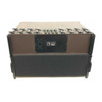
L'Acoustics dV-DOSC Operator's Manual (129 pages)
Brand:
L'Acoustics
| Category:
Stereo System
| Size: 16.56 MB
Table of Contents
Manual Organization
3
Table of Contents
4
List of Figures
6
Introduction
8
Wavefront Sculpture Technology™ Fundamentals
8
The Sound Reinforcement Problem
8
Wavefront Sculpture Principles
9
First V-DOSC, Now DV-DOSC
10
Figure 2: Wavefront Sculpture Technology Criteria
10
Summary of DV-DOSC Applications
14
Training and Qualifications
15
The Qualified V-Dosc Technician (Qvt)
15
The Certified V-Dosc Engineer (Cve)
15
ELEMENTS of the DV-DOSC SYSTEM
16
Figure 3A: System Block Diagram
17
Figure 3B: Example System Configuration
18
DV-DOSC SYSTEM COMPONENTS
19
Figure 4: DV-DOSC and Accessories
22
DV-DOSC ENCLOSURE DESCRIPTION
23
DV-DOSC FLYING SYSTEM
23
Figure 5: DV-DOSC Element - Front and Rear Views
23
Figure 6: DV-ANGLE P1 and P2 Angle Values
24
Figure 7: DV-BUMP
25
Figure 8: DV-DOWN
25
DV-DOSC AMPLIFIER RACKS
26
Figure 10: PAD 04 (4 Amplifiers Per Rack)
27
Table 1: PAD04 Amp Panel Wiring Chart
28
Figure 11: RK12-2M and RK12-2S Master and Slave Racks
29
Figure 12: PAD 02 (2 Amplifiers Per Rack)
29
Table 2: PAD02 Amp Panel Wiring Chart
30
POWERING DV-DOSC
31
Table 4: Load, RMS and Peak Power Ratings for DV-DOSC
31
Table 5: Recommended Amplifier Power Ratings for 100 Hz LR24 HPF
32
Table 6: L-ACOUSTICS la 24 MLS Settings for Use with DV-DOSC
32
Table 7: L-ACOUSTICS la 48 MLS Settings for Use with DV-DOSC
32
Figure 13: Connecting DV-DOSC to L-ACOUSTICS RK12-4
33
DV-SUB ENCLOSURE DESCRIPTION
34
DV-SUB FLYING SYSTEM
35
Figure 15: DV-ANGLESS Sub-To-Sub Angle Bar
35
Figure 17: Illustration of DV-SUB Rigging Configurations
37
POWERING DV-SUB
37
Table 10: Recommended Power and Amplifier Power Ratings for DV-SUB
37
DV-DOSC CONTROL
38
(A) General Guidelines Regarding System Protection
38
(B) Preset Policy
38
C) General Description of DV-DOSC Presets
39
D) BSS FDS 355 VERSION 6 0801 PRESETS
41
Table 11: BSS FDS 355 Presets
41
E) BSS FDS 366 VERSION 6 0801 PRESETS
42
Table 12: BSS FDS 366 Presets
42
F) XTA DP224 VERSION 6 0801 PRESETS
43
Table 13 : XTA DP224 Presets
43
G) XTA DP226 VERSION 6 0801 PRESETS
44
Table 14: XTA DP226 Presets
44
Control Signal Distribution
45
Co 24 Control Output Panel
46
Figure 18: CO24 Control Output Panel
46
Figure 19: MD24 Multi Distro Panel
47
MD 24 Multi Distro Panel
47
Cd12 Control Distro Panel
48
Figure 20: CD 12 Control Distro Panel
48
Figure 21: System Architecture Using RK12-2M Master Rack and RK12-4
50
DV-DOSC ARRAY SPECIFICATIONS
51
Isocontour in the Horizontal Plane
51
Horizontal Directivity of a DV-DOSC Array
51
Effective Coverage in the Horizontal Plane
51
Wavefront Sculpture in the Vertical Plane
52
Flat DV-DOSC Array
52
Convex Curvature DV-DOSC Array
52
Constant Curvature DV-DOSC Array
52
Variable Curvature DV-DOSC Array
53
Concave Curvature DV-DOSC Array
53
Coverage Predictions Using the Array 2000 Spreadsheet
53
CUTVIEW SHEETS (ARRAY1, ARRAY2, DV-ARRAY1, DV-ARRAY2)
54
A) Input Data
54
Figure 22: Defining Cutview Dimensions
54
Figure 23: Parameters for the ROOM DIM Utility Sheet in ARRAY
55
B) Optimization Procedure
56
C) Output Data
56
DV-DOSC DV-SUB Manual V2.0 Nov 2001
56
Figure 24: Optimizing Array Element Focus by Adjusting for Equal Spacing
56
Figure 25: Physical DV-DOSC Rigging Parameters for ARRAY
57
SIMULATING DV-DOSC DOWNFILL
58
SIMULATING DV-DOSC UPFILL
58
DV-DOSC PICK POINT UTILITY
59
H-Isocontour Sheet
59
A) Input Data
59
B) Optimization Procedure
60
C) Output Data
60
Array 2000 Spreadsheet Calculation Examples
61
Figure 26A: ARRAY 2000 Spreadsheet Calculation Example (LCR DV-DOSC System)
61
Figure 26B: Simulating DV-DOSC under V-DOSC
62
Figure 26C: Simulating DV-DOSC on Top of V-DOSC
62
Elements of Sound Design
63
Multiple Array Concepts
63
Reducing Array Interaction
63
Achieving Optimum Coverage
63
Stacked or Flown
64
Stacking Guidelines
64
Flying Guidelines
65
Subwoofers
66
General Guidelines for the Use of Subwoofers
66
Split Left/Right Ground Stacked Subwoofers
66
Flown Subwoofers
67
Central Location, Ground Stacked
68
3-WAY PRESETS for DV-DOSC and SB218 SUBWOOFERS
68
3-WAY PRESETS for DV-DOSC and DV-SUB SUBWOOFERS
68
4-WAY PRESETS for DV-DOSC and DV-SUB or SB218 SUBWOOFERS
70
Figure 14: DV-SUB
70
Installation Procedures
71
Stacked Systems
71
Stacking DV-DOSC Standalone
71
Safety Rules
72
Stacking on Top of V-DOSC
77
Stacking on Top of SB218 Subwoofers
80
Stacking DV-SUB Subwoofers
84
Stacking DV-DOSC on Top of DV-SUBS
87
Procedure 1: Stacking Without DV-BUMP
87
Procedure 2: Stacking with DV-BUMP
90
Flown Systems
92
Standalone Flying with DV-BUMP
92
Trim and Angle Adjustments
99
Flying under V-DOSC with DV-DOWN
101
Flying DV-SUB Standalone
105
Flying DV-DOSC under DV-SUB (3+1 Configuration)
108
Flying DV-DOSC under DV-SUB (Larger Configurations)
112
Procedure 1 (2 DV-SUB + 6 DV-DOSC)
112
Procedure 2 (Larger Configurations)
113
Safety Rules
118
Maintenance and Installation Tools
120
Recommended Maintenance Procedures
120
Recommended Maintenance Tools
120
Table 16: Recommended Maintenance Tools
120
Spare Parts
121
Recommended Installation Tools
122
Figure 27: Recommended Installation Tools
122
Specifications
123
DV-DOSC ELEMENT SPECIFICATIONS
123
Figure 28: DV-DOSC Element - Line Drawing
124
Table 17: DV-DOSC Weight Per Number of Cabinets
125
DV-SUB SPECIFICATIONS
126
Figure 30: Front View of DV-DOSC Array and Vertically Stacked DOSC Waveguides
128
APPENDIX 1: How Does DV-DOSC Behave with Respect to WST Criteria
129
APPENDIX 2: How Does the DOSC Waveguide Work
129
Figure 31: DOSC Waveguide - Internal Section
129
Advertisement
Related Products
L'Acoustics dV-SUB
L-ACOUSTICS 112XT
L-Acoustics 115XT HiQ
L-Acoustics A10i
L-Acoustics K3i
L-Acoustics KIVA
L'Acoustics Categories
Speakers
Subwoofer
Enclosure
Racks & Stands
Speaker System
More L'Acoustics Manuals
Login
Sign In
OR
Sign in with Facebook
Sign in with Google
Upload manual
Upload from disk
Upload from URL