Sign In
Upload
Manuals
Brands
Kubota Manuals
Tractor
MX5000
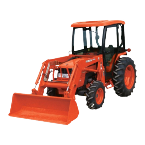
Kubota MX5000 Utility Tractor Manuals
Manuals and User Guides for Kubota MX5000 Utility Tractor. We have
1
Kubota MX5000 Utility Tractor manual available for free PDF download: Workshop Manual
Kubota MX5000 Workshop Manual (317 pages)
Brand:
Kubota
| Category:
Tractor
| Size: 43.29 MB
Table of Contents
Safety Introduction
3
Before Servicing and Repairing
3
Safety Working
4
Specifications
9
Travelling Speeds
10
Dimensions
11
General
12
Contents
13
Tractor Identification
14
General Precautions
15
Handling Precautions for Electrical Parts and Wiring
16
Battery
18
Fuse
18
Connector
18
Handling of Circuit Tester
19
Lubricants, Fuel and Coolant
20
Tightening Torques
21
General Use Screws, Bolts and Nuts
21
Maintenance
22
Check and Maintenance
23
Daily Check
23
Check Points of Initial 50 Hours
24
Changing Engine Oil
24
Replacing Engine Oil Filter Cartridge
24
Changing Transmission Fluid
25
Replacing Hydraulic Oil Filter Cartridge
26
Changing Front Axle Case Oil [4WD Type]
26
Check Points of Every 50 Hours
27
Greasing
27
Checking Engine Start System
28
Checking Wheel Mounting Screws and Nuts Tightening Torque
28
Check Points of Every 100 Hours
29
Checking Battery Condition
29
Cleaning Air Cleaner Element
30
Cleaning Fuel Filter Element and Filter Bowl
30
Adjusting Fan Belt Tension
31
Adjusting Clutch Pedal Free Travel
31
Adjusting Brake Pedal Free Travel
31
Checking Fuel Line
32
Check Points of Every 200 Hours
33
Checking Radiator Hose and Hose Clamp
33
Checking Power Steering Oil Line
33
Toe-In
34
Checking Intake Air Line
34
Check Points of Every 400 Hours
35
Replacing Fuel Filter Element
35
Check Points of Every 600 Hours
35
Adjust Front Axle Pivot
35
Check Points of Every 800 Hours
36
Checking Valve Clearance
36
Check Points of Every 1500 Hours
37
Check Points of Every 3000 Hours
37
Check Points of Every 1 Year
37
Check Points of Every 2 Years
37
Flushing Cooling System and Changing Coolant
38
Anti-Freeze
39
Bleeding Fuel System
40
Draining Clutch Housing Water
40
Replacing Fuse
40
Replacing Light Bulb
41
Special Tools
42
Special Tools for Engine
42
Valve Guide Replacing Tool
45
Injection Pump Pressure Tester
45
Bushing Replacing Tools
46
Flywheel Stopper
46
Crankshaft Bearing 1 Replacing Tool
47
Balancer Metal Replacing Tool (for Removing)
48
Balancer Metal Replacing Tool (for Fitting)
49
Special Tools for Tractor
50
Pinion Shaft Remover
52
Hydraulic Arm Shaft Bushing Press-Filling Tool
53
Draft Control Test Bar
53
Tires
54
Types of Tire
54
Treads Adjustment
55
Front Wheels
55
Rear Wheels
56
Wheel Hub
57
Tire Pressure
58
Tire Liquid Injection
59
Preparation of Calcium Chloride Solution
59
Attaching Injector
59
Injection
60
Draining Water or Solution
61
Implement Limitations
62
Engine
64
Servicing
66
Troubleshooting
67
Servicing Specifications
70
Checking, Disassembling and Servicing
77
Separating Engine from Tractor
77
Draining Engine Oil
77
Bonnet, Front Lower Cover
78
Draining Coolant
78
Wiring, Pipes and Hoses
79
Steering Wheel, Meter Panel and Rear Bonnet
80
Steering Hoses
80
Propeller Shaft (4WD Only)
81
Separating Engine and Clutch Housing
81
Muffler and Hoses
82
Fuel Tank and Tank Support
82
Separating Engine from Front Axle Frame
82
Outer Parts of Engine
83
Clutch Assembly
83
Engine Body
84
Checking and Adjusting
84
Compression Pressure
84
Valve Clearance
85
Top Clearance
86
Cylinder Head Cover
86
Cylinder Head and Valves
86
Injection Pipes
87
Nozzle Holder Assembly and Glow Plug
87
Nozzle Heat Seal Service Removal Procedure
87
Rocker Arm and Push Rod
88
Cylinder Head
88
Tappets
88
Valves
89
Timing Gears, Camshaft Anf Fuel Camshaft
89
Injection Pump
89
Speed Control Plate
90
Fan Drive Pulley
90
Gear Case
90
Crankshaft Oil Slinger
90
Idle Gear
91
Fuel Camshaft and Fork Level Assembly
91
Camshaft and Balancer Shaft
91
Crank Gear
92
Oil Pump
92
Piston and Connecting Rod
92
Connecting Rod Cap
92
Pistonts
93
Piston Ring and Connecting Rod
94
Crankshaft
95
Flywheel
95
Bearing Case Cover
95
Main Bearing Case Assembly
96
Cylinder Heat Surface Flatness
96
Cylinder Head Flaw
97
Valve Recessing
97
Clearance between Valve Stem and Valve Guide
97
Replacing Valve Guide
98
Valve Seating
98
Correcting Valve and Valve Seat
99
Valve Lapping
99
Free Length and Tilt of Valve Spring
100
Valve Spring Setting Load
100
Oil Clearance between Rocker Arm and Rocker Arm Shaft
100
Push Rod Alignment
100
Oil Clearance between Tappet and Tappet Guide Bore
101
Timing Gear, Camshaft and Fuel Camshaft
101
Timing Grear Backlash
101
Idle Gear Side Clearance
102
Camshaft Side Clearance
102
Oil Clearance of Balancer Shaft Journal
103
Oil Clearance between Idle Gear Shaft and Idle Gear Bushing
103
Replacing Idle Gear Bushing
104
Camshaft Alignment
104
Cam Height
104
Oil Clearance of Camshaft Journal
105
Oil Clearance between Piston Pin and Small End Bushing
105
Replacing Connecting Rod Small End Bushing
106
Piston Ring Gap
106
Clearance between Piston Ring and Groove
106
Connecting Rod Alignment
107
Side Clearance of Crankshaft
107
Crankshaft Alignment
108
Oil Clearance between Crankpin and Crankpin Bearing
108
Oil Clearance between Crankshaft Journal and Crankshaft Bearing 1
109
Replacing Crankshaft Bearing 1
109
Oil Clearance between Crankshaft Journal and Crankshaft Bearing 2
110
Crankshaft Sleeve Wear
110
Replacing Crankshaft Sleeve
111
Cylinder Wear
111
Correcting Cylinder (Oversize +0.25Mm)
112
Lubricating System
113
Engine Oil Pressure
113
Rotor Lobe Clearance
113
Clearance between Rotor and Cover
114
Cooling System
114
Fan Belt Tension
114
Fan Belt Damage and Wear
114
Thermostat Valve Opening Temperature
115
Radiator Cap Air Leakage
115
Fuel System
116
Injection Timing
116
Fuel Tightness of Pump Element
117
Fuel Tightness of Delivery Valve
117
Nozzle Injection Pressure
118
Nozzle Spraying Condition
118
Valve Seat Tightness
118
Disassembling and Assembling
119
Nozzle Holder
119
Clutch
120
Mechanism
121
Travelling Clutch
122
Linkage Mechanism
122
PTO Clutch
123
Shift Linkage
123
Structure
123
[3] Oil Flow
124
Checking Clutch Pedal Free Travel
129
Separating Clutch Housing and Engine
129
Release Holder and Clutch Lever
133
Backlash between Clutch Disc Boss and Gear Shaft
134
Thrust Ball Bearing
134
Clutch Disc Wear
134
Checking Pressure Plate Assembly and Flywheel
134
Pressure Plate Flatness
135
Hydraulic PTO Clutch
136
Relief Valve Setting Pressure
136
Draining the Transmission Fluid
137
Battery Negative Table
137
Hydraulic Pipes
137
Wirings
138
Hydraulic Block and Pipes
138
Separating Clutch Housing and MID Case
139
PTO Clutch Valve, PTO Clutch and Holder
139
Clutch Fub and Clutch Discs
140
Modulating Valve
140
Clutch Case
141
Brake Plate
141
PTO Steel Plate Wear
142
Flatness of PTO Piston and PTO Steel Plate
142
Piston Return Spring Free Length
142
Thickness of Seal Ring
143
Hose and Pipes
144
PTO Clutch Valve
144
Clutch Valve Assembly
144
Clutch Valve Spool
145
Transmission
146
Clutch Housing Case and MID Case
154
Steering Wheel, Meter Panel and Rear B Onnet
156
Pedal Frame and Step
158
Suction Pipe and Hydraulic Block
158
Shaft Case
159
Clutch Lever, Release Fork and Release Bearing
159
24T Gear Shaft and 27T Gear
160
Front Axle Drive Shaft (4WD Only)
160
Front Axle Drive Shaft Tool
160
Clutch Housing Bearing Holder
161
Shaft Assemblies
161
MID Case, 19T Grear Shaft and 21T Grear Shaft
161
Checking Bearing
162
Clearance between Gear and Spline
162
Clearance between Shift Fork and Shift Gear Groove of Shifter Groove
162
Transmission Care
163
Rear Wheels and Seat
163
Step and Center Cover
164
Pipes and Hydraulic Block
164
ROPS and Fender R.H., L.H.
165
Hydraulic Cylinder Assembly
166
Brake Case
167
Separating MID Case and Transmission Case
167
Transmission Bearing Holder
168
Differential Lock Shift Fork
169
Differential Gear Assembly
169
Bearing and Differential Lock Shifter
170
Differential Case Cover and Differential Side Gear
170
Spiral Bevel Gear
170
Differential Pinion Shaft and Differential Pinion
171
Differential Side Gear
171
Spiral Bevel Gear Turning Torque
172
Backlash and Tooth Contact between Spiral Bevel Gear Ans Spiral Bevel Pinion Shaft
173
Clearance between Differential Case Bore and Differential Side Gear Boss
174
Clearance between Differential Pinion Shaft and Differential Pinion
174
Backlash between Differential Pinion and Differential Side Gear
174
Rear Axle
175
Separating Rear Axle Case from Brake Case
181
Rear Wheel
181
Rops
181
Rear Axle Case
182
Disassembling Rear Axle
183
Brakes
184
Brake Pedal
191
Checking Brake Pedal Free Travel
191
Clearance between Brake Lever Link Shaft and Bushing
192
Separating Brake Case from Transmission Case Draining the Transmission Fluid
192
Brake Cam and Brake Cam Lever
194
Brake Cam Lever Movement
195
Cam Plate Flatness
195
Height of Cam Plate and Ball
195
Brake Disc Wear
195
Front Axle
196
2WD Type
198
4WD Type
199
Axial Sway of Front Wheel
208
Adjusting Front Axle Pivot
209
Front Wheel Steering Angle (4WD Only)
209
Draining Front Axle Case Oil (4WD Only)
210
Power Steering Hoses
211
Front Wheel and Front Axle
211
Tie-Rods
211
Disassembling 2WD Type Front Axle Front Wheel Hub
212
Knuckle Shaft
213
Disassembling 4WD Type Front Axle
213
Bevel Gear Case and Front Gear Case
213
Axle Flange and Front Gear Case
214
Bevel Gear and Bevel Gear Shaft
214
Bevel Gear Case
214
Bevel Gear Case Gears
214
Axle
215
Spiral Bevel Pinion Shaft and Differential Gear Assembly
216
Differential Gear
217
Clearance between Front Axle Middle Boss and Shaft Bracket Bushing
218
Clearance between Knuckle Shaft (Kingpin) and Bushing
218
Clearance between Differential Case (Differential Case Cover) and Differential Side Gear
219
Clearance between Pinion Shaft and Differential Pinion
219
Turning Torque of Spiral Bevel Pinion Shaft (Pinion Shaft Only)
220
Backlash between Spiral Bevel Pinion Shaft and Spiral Bevel Gear
220
Backlash between 10T Bevel Gear and 14T Bevel Gear
221
Backlash between 9T Bevel Gear and 43T Bevel Gear
221
Clearance between Front Axle Case Bosses and Bracket Bushings
222
Clearance between Bevel Gear Case Boss and Front Axle Support Bushing
222
Steering
223
Steering Linkage
225
[2] Oil Flow
226
Steering Cylinder
227
Power Steering Hydraulic Pum
231
Steering Controller
231
Steering Cylinder [2WD Type]
231
Steering Cylinder [4WD Type]
231
Steering Linkage [2WD]
232
Power Steering Hydraulic Pump
234
Hydraulic Flow Test
235
Removing Hydraulic Pump Assembly
236
Regulator Valve and Hydraulic Pump Assembly
236
Disassembling Power Steering Hydraulic Pump
237
Hydraulic Pump Running-In
237
Housing Bore (Depth of Scratch)
237
Side Plate Thickness
238
Relief Valve Setting Pressure Test
238
Removing Steering Controller
239
Disassembling Steering Controller
240
Port Cover Assembly
241
Port Manifold and Springs
241
Valve Ring
242
Springs and Isolation Manifold
242
Alignment Pins and Drive Link
242
Metering Ring and Metering Package
243
Face Seal, Face Seal Spacer, Thrust Bearing and Bearing Spacer
243
Commutator Seal
243
Commutator Cover
244
Commutator Ring
245
Commutator and Alignment Pins
245
Drive Link Spacer and Rotor Set
245
Port Cover
245
Port Manifold
246
Valve Plate
246
Hex. Drive Assembly
246
Isolation Manifold
246
Commutator Ring and Commutator
247
Drive Link Spacer
247
Rotor Set
247
Drive Plate
248
Bearing and Spacers
248
Battery, Bonnet and Lower Cover
249
Radiator and Battery Support
249
Removing Steering Cylinder
250
Removing Pitman Arm
251
Disassembling Steering Cylinder [2WD Type]
251
Rod End
251
Cylinder Cover Assembly and Rod Assembly
252
Removing the Steering Cylinder [4WD Type]
253
Disassembling Steering Cylinder [4WD Type]
254
Piston Rod
254
Clearance between Rod and Cylinder Cover Bushing
254
Cylinder Tube Wear
254
Clearance between Rod End Shaft and Rod End Bushing
255
Clearance between Cylinder Tube Pin and Pitman Arm Bushing
255
Clearance between Pitman Arm Shaft and Pitman Arm Bushing
255
Steering Cylinder (4WD Type)
256
Steering Cylinder I.D.
256
Clearance between Bod and Bushing
256
Hydraulic System
257
Hydraulic Circuit
259
Hydraulic Circuit for Three Point Hydraulic System
261
Hydraulic Oil Flow
261
Three Point System Hydraulic Pump
264
Relief Valve
264
Cylinder Safety Valve
264
Control Linkage
264
Hydraulic Cylinder
265
Hydraulic Pump
267
Pump Test Using Flow-Meter
267
Regulator Valve and Hydraulic Pump Assembly
270
Disassembling Three System Hydraulic Pump
270
Separating Power Steering Hydraulic Pump
270
Position Control and Draft Control Linkage
272
Adjusting Position Control Feedback Rod
272
Adjusting Draft Control Rod (if Equipped)
273
Seat and Level Guide
273
Position Control and Draft Control Linkage (if Equipped)
274
Relief Valve Setting Pressure Test Using Pressure Tester
275
Operating Pressure of Cylinder Safety Valve
276
Hydraulic Cylinder and Position Control Valve
277
Battery Negative Cable
277
Seat and Fender Support
277
3P Delivery Pipe
277
Disassembling Hydraulic Cylinder Assembly
279
Hydraulic Rod and Hydraulic Piston
279
Lift Arm, Hydraulic Arm and Hydraulic Arm Shaft
279
Bushings
280
Position Control Valve
280
Lowering Speed Adjusting Valve
282
Hydraulic Cylinder Bore
282
Clearance between Hydraulic Arm Shaft and Bushing
282
Electrical System
283
Wiring Diagram
285
Color of Wiring
285
Easy Checker
290
Battery Voltage
294
Battery Terminal Connection
294
Battery Specific Gravity
295
Starting System
296
Main Switch
296
Connector Voltage
296
Main Switch Key at off Position
296
Main Switch Key at on Position
297
Main Switch Key at START Position
297
Main Switch Key at PREHEAT Position
297
Motor Test
297
Magnet Switch Test (Pull-In, Holding Coils)
298
Checking Starter Relay
298
Glow Contol System
298
Glow Plug Lead Terminal Voltage
298
Glow Plug Continuity
299
Safety Switch Continuity
299
Starter
299
Disassembling Motor
299
Disassembling Magnet Switch
300
Plunger
300
Overrunning Clutch
300
Commutator and Mica
301
Brush Wear
301
Brush Holder
301
Armature Coil
302
Field Coil
302
Charging System
303
Alternator
303
No-Load Test
303
Rear End Cover
304
IC Regulator
304
Rectifier
304
Rear End Frame
305
Rotor
305
Retainer Plate
305
Bearing on Drive End Side
305
Slip Ring
306
Lighting System
308
Combination Switch
308
Remove the Combination Switch
308
Head Light Switch Continuity When Setting Switch at off Position
309
Head Light Switch Continuity When Setting Switch at ON1 Position
309
Head Light Switch Continuity When Setting Switch at ON2 Position
309
Turn Signal Switch
309
Turn Signal Switch off Position
310
Turn Signal Switch R Position
310
Turn Signal Switch L Position
310
Nazard Switch Connector Voltage
310
Nazard Switch Continuity
311
Flasher Unit
312
Flasher Unit Test
312
Warning Lamps
313
Engine Oil Pressure Switch Panel Board and Wiring Harness
313
Engine Oil Pressure Switch Continuity
313
Charging Circuit (Panel Board and Wiring Harness)
313
Gauges
314
Fuel Level Sensor
314
Coolant Temperature Sensor
314
Guel Gauge and Coolant Temperature Gauge Continuity
314
Advertisement
Advertisement
Related Products
Kubota MX5100
Kubota MX5200
Kubota MX5800
Kubota MX5400
Kubota MX4800
Kubota MX Series
Kubota MX6000
Kubota M105S
Kubota M9000DT-M
Kubota M6L-111
Kubota Categories
Tractor
Lawn Mower
Engine
Farm Equipment
Excavators
More Kubota Manuals
Login
Sign In
OR
Sign in with Facebook
Sign in with Google
Upload manual
Upload from disk
Upload from URL