Sign In
Upload
Manuals
Brands
Krone Manuals
Farm Equipment
Big Pack 1290
Krone Big Pack 1290 Large Square Baler Manuals
Manuals and User Guides for Krone Big Pack 1290 Large Square Baler. We have
5
Krone Big Pack 1290 Large Square Baler manuals available for free PDF download: Original Operating Instructions, Operating Instructions Manual
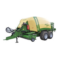
Krone Big Pack 1290 Original Operating Instructions (568 pages)
Baler
Brand:
Krone
| Category:
Farm Equipment
| Size: 22.42 MB
Table of Contents
Table of Contents
3
To this Document
12
Validity
12
Re-Ordering
12
Further Applicable Documents
12
Target Group of this Document
12
To this Document
13
Direction Information
13
Directories and References
13
Figures
13
How to Use this Document
13
Term "Machine
13
Means of Representation
14
Scope of Document
14
Direction of Travel
15
Intended Use
18
Purpose of Use
18
Safety
18
Service Life of the Machine
18
Basic Safety Instructions
19
Importance of the Operating Instructions
19
Personnel Qualification
19
Additional Equipment and Spare Parts
20
Children in Danger
20
Connect the Machine to the Tractor
20
Structural Changes to the Machine
20
Workstations and Passengers
20
Operational Safety: Technically Perfect Condition
21
Danger Zones
22
Keeping Safety Devices Functional
24
Personal Protective Equipment
24
Safety Signs on the Machine
25
Traffic Safety
25
Consumables
26
Dangers Associated with the Operational Environment
26
Parking the Machine Safely
26
Sources of Danger on the Machine
27
Dangers Associated with Certain Activities: Climbing up and down
28
Dangers Associated with Certain Activities: Work on the Machine
28
Behaviour in Hazardous Situations and When Accidents Occur
29
Dangers Associated with Certain Activities: Working on Wheels and Tyres
29
Safety Routines
30
Stopping and Securing the Machine
30
Supporting Lifted Machine and Machine Parts Securely
30
Coupling the Machine Safely
31
Uncoupling the Machine Safely
31
Preparing the Machine for Repair, Maintenance and Adjustment Work
32
Starting the Machine Safely
32
Safety Stickers on the Machine
33
Attaching Safety Labels and Information Labels
43
Contact
43
Re-Ordering Safety Labels and Information Labels
43
Fire Extinguisher
44
Ladder
44
Safety Equipment
44
Parking Brake
45
Wheel Chocks
45
Flywheel Brake
46
Parking Jack
46
Mechanical Support Twine Box
48
Shut-Off Valve Pick-Up
48
Data Memory
49
Left Side of the Big Pack Baler with Tandem Axle
50
Machine Description
50
Machine Overview
50
Right-Hand Side of Large Square Baler Big Pack with Tandem Axle
52
Identification Plate
53
Information Required for Questions and Orders
53
Description of the Baling Process
54
Compacting the Big Bale
55
Multibale Design
56
Drives
58
Main Drive
58
Feeder Packer
60
Main Drive
60
Overload Protections on the Machine
60
Cutting System Drive for the Design with XC Cutting System
61
Pick-Up Drive
61
Needle Yoke
62
Pick-Up
62
Cutting Length
63
Cutting System
63
General
63
Roller Crop Guide
63
Hydraulic System
64
Pressure Limiting Valve Block (On-Board Hydraulic System)
65
Twine
66
Electrical Twine Empty Display for Lower Thread
67
Electrical Knotter Monitoring
68
Twine Motion Indicator Upper Twine (Double Knotter)
68
Knotter Gear
69
Bale Ejector / Bale Chute
70
Medium Version Electronics Design
70
For Comfort Version Electronics Design
71
Compressed-Air Reservoir
72
Technical Data
73
Technical Data of the Machine
73
Airborne Sound Emission
77
Ambient Temperature
77
Tyres
77
Consumables
78
Filling Quantities and Lubrication Designations for Gearboxes
78
Oil Quantities and Designations for the Compressor
79
Oil Quantities and Designations for the On-Board Hydraulic System
79
Control and Display Elements
80
Control Units of the Tractor
80
Operation Terminal
81
Commissioning
82
Attaching Hydraulic Parking Jack
83
Electrical Power Supply
85
Adjusting the Drawbar Height
86
Adjusting the Height of the Drive Train
87
Shortening Universal Shaft
88
Adjusting the Hydraulic System
93
Operating the Machine Via LS (Load-Sensing Connection)
93
Operating the Machine Without LS (Load-Sensing Connection)
93
Setting the Bale Chute
94
With Bale Scale Design
94
Bale Brake
95
Start-Up
96
Connect the Machine to the Tractor
97
Install the PTO Shaft
98
Hydraulics
100
Connecting the Hydraulic Lines
101
Hydraulic Brake (Export)
103
Putting down ISO Plug
103
Hydraulic Brake (Export France)
104
Compressed Air Connections for the Compressed Air Brake
105
Connecting KRONE ISOBUS-Terminal
106
Connecting External ISOBUS-Terminal
110
Connecting the Joystick
111
Lighting
114
Using the Safety Chain
114
Driving and Transport
116
Preparations for Road Travel
117
Bale Chute Hydraulically Actuated
118
Bale Chute in Transport Position (Optional)
118
Checking the Lighting System
119
Parking Brake
119
Handling the Coaster/Steering Axle (Special Equipment)
120
Operating the Machine Via LS (Load-Sensing Connection)
122
Operating the Machine Without LS (Load-Sensing Connection)
122
Moving the Machine Without Hydraulic Connections
123
Moving
124
Switching off the Machine
125
Parking Brake
126
Wheel Chocks
126
Stowing the Compressed Air Hoses
127
Preparing the Machine for Transportation
128
Securing Side Guard
128
Securing Guide Wheels
129
KRONE ISOBUS Terminal [Medium/Comfort Version Electronics]
130
ISOBUS Shortcut Button
131
Touch Sensitive Display
132
Switching Terminal on or off
133
Display Design
134
KRONE ISOBUS Terminal [Medium Plus/Comfort Plus Version Electronics]
135
External ISOBUS Terminal
136
General Information on ISOBUS
136
Deviating Functions from KRONE ISOBUS Terminal
137
ISOBUS Shortcut Button Not Available
137
Status Line
138
Terminal - Machine Functions [Medium/Comfort Version Electronics]
138
Keys
140
Displays in the Working Screen</Dg_Bm "Text_Mod_1443538650498_0001
142
Changing to Automatic Mode
146
Changing to Manual Mode
146
Selecting Working Screens
146
Selecting Road Travel Screen
147
Selecting Other Functions
148
Switching the Warning Beacon On/Off
148
Switching Working Floodlights on and off
148
Locking / Releasing Steering Axle
149
Opening/Closing the Bale Channel Flaps
149
Switching the Starting Aid On/Off
149
Automatic Bale Ejection
150
Calling Menu "Counter/Detail Couner
150
Changing to Automatic Mode
150
Changing to Manual Mode
150
Lower the Bale Chute
150
Raising/Lowering the Blade Bar
151
Reset Bale Length to Zero
151
Trigger Knotter
151
Setting the Target Bale Channel Flap Pressure (Manual Mode)
152
Setting Target Force of Pressure (Automatic Mode)
153
Setting Bale Length (Manual and Automatic Mode)
154
Setting the Number of Multibales
155
Auxiliary Functions (AUX)
156
Operating Machine Via Joystick
156
Example of a Joystick Assignment for Fendt (Default Setting)
157
Recommended Assignment of a WTK- Multi-Function Lever
158
Terminal - Machine Functions [Medium Plus/Comfort Plus Version Electronics]
159
Menu Structure
160
Terminal - Menus [Medium/Comfort Version Electronics]
160
Recurring Icons
162
Calling up the Menu Level
163
Changing the Value
164
Changing Mode
165
Menu 1 "Knotter
166
Menu 1-1 "Correction Value for Bale Length
167
Menu 1-2 "Knotter Signal
168
Menu 1-3 "Knotter Monitoring
169
Menu 1-4 "Blow Interval
170
Menu 1-5 "Blowing Time
171
Menu 2 "Sensitivity of Direction Indicator
172
Menu 3 "Central Lubrication
173
Menu 4 "Bale Scales
174
Menu 5 "Moisture Measurement
176
Menu 5-1 "Alarm Message for Moisture Measurement
177
Menu 5-2 "Correction Value for Moisture Measurement
178
Menu 6 "Silage Additive System
179
Menu 13 "Counters
180
Menu 13-1 "Customer Counter
181
Menu 13-1 Selecting Detail Counter/Customer Counter
183
Menu 13-2 "Total Counter
186
Menu 14 "ISOBUS Settings
188
Menu 14-1 "Diagnostics Auxiliary (AUX)
188
Menu 14-2 "Diagnostics for Driving Speed / Direction Indicator
189
Menu 14-8 "Configuring Main Window
190
Menu 14-9 "Switching between the Terminals
193
Menu 15 "Settings
194
Menu 15-1 "Sensor Test
195
Checking/Adjusting Sensor B22 "Bale on Chute
202
Setting Sensor B38 "Acceleration Sensor
204
Setting Sensor B55 "Bale Chute at Rear"/Sensor B56 "Bale Chute at Front
205
Menu 15-2 "Actuator Test
206
Menu 15-5 "Software Info
210
Menu 15-6 "Technician Level
211
Alarm Messages
212
Alarms
213
Logical Alarms
215
Physical Alarms
219
Terminal - Menus [Medium Plus/Comfort Plus Version Electronics]
223
Operation
224
Preparation for Baling
224
Setting the Tying Twine in Place
226
Tying Unit
226
Threading in the Lower Twine
230
Threading in the Upper Twine
231
Threading in the Lower Twine
235
Threading in the Upper Twine
236
Pick-Up
238
Lifting / Lowering Bale Chute
239
Medium Electronics Design
239
Comfort Version Electronics Design
240
Operating Bale Ejector
241
Parking Jack
243
Hydraulic Parking Jack
244
Bale Brake
245
Working Floodlight
246
Finishing Tying Process Manually
247
Initiating the Tying Process Manually
247
Removing Blockages
248
Settings
250
Default Setting (Working Height Setting)
251
Pick-Up
251
Setting the Ground Pressure of the Guide Wheels
252
Driving with Pick-Up in Fixed Position
253
Roller Crop Guide
254
Lateral Setting of the Needles
255
Setting the Needles
255
Setting the Height of the Needles on the Knotter
256
Top Dead Centre of the Needles
257
Adjusting the Multibale
258
Setting the Height of the Needle Yoke Brake
258
Setting the Position of the Second Needle Yoke
258
Setting the Stop
258
Setting the Locking (Frame)
259
Setting the Lockings of the Needle Yoke
259
Possible Setting Errors and Their Elimination (Multibale)
260
Setting the Rubber Pad between the Needle Yokes
260
Checking / Adjusting Position of Needles - Baling Ram
261
Checking / Setting Upper Needle
262
Checking / Setting the Twine Bar to the Lower Needle (Needle Yoke)
263
Checking / Setting Twine Bar
263
Checking / Setting Twine Bar to the Channel Slot
264
Tensioning/Relieving the Upper Needle Shaft
266
Adjusting the Knotter Shaft Brake
267
Tensioning/Relieving the Twine Locking Shaft
267
Setting the Twine Brake
268
Setting the Twine Tension on the Upper Twine Strand (Double Knotter)
269
Setting the Twine Tension of the Lower Twine Strand (Double Knotter)
270
Knotter
271
Locking/Releasing the Tying Process
271
Double Knotter
272
Setting the Knotter Hook
272
Start-Up
272
Setting of Twine Retainer
273
Setting the Holding Force of the Twine Retainer
274
Adjusting the Baling Ram
276
Setting the Baling Ram Blades
276
Setting the Lateral Plunger Blades
278
Cleaning the Running Rails
279
Lateral Setting of the Plunger
279
Adjusting the Packer Relative to the Plunger
280
Description of Components
280
Checking Packer Coupling
282
Moving Packer Strip into Position
282
Moving Baling Ram into Position
283
Component Description Variable Filling System
284
Presetting Threaded Rod / Stop for the Feeler Rocker
285
Zero Position (VFS System)
286
Adjusting the Zeroizing Device
287
Adjusting the Spring in the Zeroizing Device
288
Setting the Rubber Buffer on the Zero Adjuster
288
Adjusting the Triggering Sensitivity
289
Adjusting the Feeler Rocker
290
Adjusting the Feeler Rocker Stop
291
Absorbing Mechanism
293
Default Setting of Belt Brake (Flywheel)
294
Adjusting the Chop Length
295
Maintenance
299
Spare Parts
299
Maintenance Table
300
Metric Thread Screws with Control Thread
302
Tightening Torques
302
Metric Thread Screws with Countersunk Head and Hexagonal Socket
303
Metric Thread Screws with Fine Thread
303
Blade Changing
304
Eyebolts for Lifting
306
Lifting
306
Cleaning
307
Conveyor Roller (I)
308
Drive Chains
308
Pick-Up Drive (II)
308
Pick-Up Drive (III)
309
Tyres
310
Checking and Maintaining Tyres
311
Maintenance - Hydraulic System
312
On-Board Hydraulic System
313
High-Pressure Filter
314
Emergency Manual Activation
315
Comfort Hydraulic Block Diagram
316
Examples of Emergency Manual Activation
317
Raising / Lowering the Roller Chute
317
Pressing Force Control (with Emergency Manual Activation)
318
Releasing the Bale Channel Chamber (Comfort)
318
Setting the Baling Pressure
318
Main Gearbox
319
Maintenance - Gearbox
319
Packer Gearbox
320
Transfer Gearbox
321
Pick-Up Gearbox
322
Cutting System Drive Gear
323
Maintenance - Brake System
325
Compressed-Air Reservoir
326
Checking the Drain Valve
327
Retighten Tensioning Belts
327
Adjusting the Transfer Mechanism
328
Pneumatic Brake Cylinders
329
Air Filter for Pneumatic Cylinder (Only Multibale)
330
Replacing Rolls
330
Compressor
332
Maintenance Compressor
332
Maintenance - Lubrication
334
General
335
Lubricants
335
Lubricating the Cardan Shaft
336
Lubricating the Rollers for the Blade Lever
337
Manual Lubrication Points on the Machine
338
Automatic Centralised Lubrication System (Optional)
342
Maintenance - Central Lubrication
342
Maintenance - Electrical System
344
Position of Sensors (Right Side of the Machine)
344
Position of Sensors (Left Side of Machine)
346
Adjusting the Sensors
348
Namur Sensor D = 8 MM
348
Namur Sensor D = 30 MM
349
Malfunctions - Causes and Remedies
350
General Malfunctions
351
Malfunctions on the Knotter
355
Single Knotter
355
Double Knotter
358
Troubleshooting in the Central Lubrication
369
Placing in Storage
370
At the End of the Harvest Season
371
Before the Start of the New Season
372
Overload Coupling on Flywheel
373
Disposal of the Machine
374
Appendix
375
Diagram
375
On-Board Hydraulic System for Medium Version Electronics
375
On-Board Hydraulic System for Comfort Version Electronics
376
Work Hydraulics Medium Version Electronics
377
Advertisement
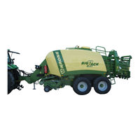
Krone Big Pack 1290 Original Operating Instructions (418 pages)
Brand:
Krone
| Category:
Farm Equipment
| Size: 19.69 MB
Table of Contents
1 Table of Contents
3
2 Foreword
11
3 To this Document
12
Validity
12
Target Group of this Document
12
How to Use this Document
12
Directional Information
12
Representation and Utilization of Warning Notes
13
Identification of the Hazard Warnings
13
4 Safety
14
Purpose of Use
14
Intended Use
14
Service Life of the Machine
14
Basic Safety Instructions
15
Importance of the Operating Instructions
15
Personnel Qualification
15
Children in Danger
16
Connect the Machine to the Tractor
16
Structural Changes to the Machine
16
Additional Equipment and Spare Parts
16
Workstations and Passengers
16
Operational Safety: Technically Perfect Condition
17
Danger Zones
18
Keeping Safety Devices Functional
20
Personal Protective Equipment
20
Safety Signs on the Machine
21
Traffic Safety
21
Parking the Machine Safely
22
Consumables
22
Dangers Associated with the Operational Environment
22
Sources of Danger on the Machine
23
Dangers Associated with Certain Activities: Climbing up and down
24
Dangers Associated with Certain Activities: Work on the Machine
24
Dangers Associated with Certain Activities: Working on Wheels and Tyres
25
Behaviour in Hazardous Situations and When Accidents Occur
25
Safety Routines
26
Stopping and Securing the Machine
26
Supporting Lifted Machine and Machine Parts Securely
26
Coupling the Machine Safely
27
Uncoupling the Machine Safely
27
Preparing the Machine for Repair, Maintenance and Adjustment Work
28
Starting the Machine Safely
28
Safety Stickers on the Machine
29
Position of the General Information Labels on the Machine
40
Re-Ordering the Adhesive Safety and Information Labels
40
Affixing the Adhesive Safety and Information Labels
40
Contact
41
Safety Equipment
42
Ladder
42
Fire Extinguisher
43
Wheel Chocks
44
Parking Brake
44
Flywheel Brake
45
Parking Jack
45
Shut-Off Valve Pick-Up
47
5 Machine Description
48
Machine Overview
48
Left Side of the Big Pack Baler with Tandem Axle
48
Right-Hand Side of Large Square Baler Big Pack with Tandem Axle
50
Identification Plate
51
Information Required for Questions and Orders
51
Contact
51
Description of the Baling Process
52
Compacting the Big Bale
53
Multibale Design
54
Drives
56
Main Drive
56
Overload Protections on the Machine
58
Main Drive
58
Feeder Packer
59
Cutting System Drive for the Design with XC Cutting System
60
Pick-Up Drive
60
Needle Yoke
61
Pick-Up
61
Roller Crop Guide
62
Cutting System
63
General
63
Cutting Length
63
Hydraulic System
64
Pressure Limiting Valve Block (On-Board Hydraulic System)
65
Twine
66
Electrical Twine Empty Display for Lower Thread
69
Twine Motion Indicator Upper Twine (Double Knotter)
70
Electrical Knotter Monitoring
70
Knotter Gear
71
Bale Ejector / Bale Chute
72
Medium Version Electronics Design
72
For Comfort Version Electronics Design
73
Compressed-Air Reservoir
74
Technical Data
75
Consumables
95
Filling Quantities and Lubrication Designations for Gearboxes
95
Oil Quantities and Designations for the On-Board Hydraulic System
96
Oil Quantities and Designations for the Compressor
96
6 Control and Display Elements
97
Connecting the Hydraulic Lines
97
7 Commissioning
98
Attaching Hydraulic Parking Jack
99
Electrical Power Supply
101
Adjusting the Drawbar Height
102
Adjusting the Height of the Drive Train
103
Shortening Universal Shaft
104
Adjusting the Hydraulic System
109
Operating the Machine Without LS (Load-Sensing Connection)
109
Operating the Machine Via LS (Load-Sensing Connection)
109
Setting the Bale Chute
110
With Bale Scale Design
110
Bale Brake
111
8 Start-Up
112
Connect the Machine to the Tractor
113
Install the PTO Shaft
114
Hydraulics
116
Connecting the Hydraulic Lines
116
Hydraulic Brake (Export)
118
Hydraulic Brake (Export France)
119
Compressed Air Connections for the Compressed Air Brake
120
Electrical Connections
121
Connecting the Terminal (on Tractors Without ISOBUS System)
121
Connecting the Terminal (on Tractors with Integrated ISOBUS System)
122
Lighting
123
Using the Safety Chain
123
9 Driving and Transport
125
Preparations for Road Travel
126
Bale Chute Hydraulically Actuated
127
Checking the Lighting System
128
Parking Brake
128
Handling the Coaster/Steering Axle (Special Equipment)
130
Operating the Machine Via LS (Load-Sensing Connection)
132
Operating the Machine Without LS (Load-Sensing Connection)
132
Moving the Machine Without Hydraulic Connections
133
Moving
134
Switching off the Machine
135
Parking Brake
136
Wheel Chocks
136
Stowing the Compressed Air Hoses
137
10 KRONE ISOBUS Terminal
138
Installing the Terminal into Cabin
139
ISOBUS Short Cut Button
140
Connecting the Multi-Function Lever to the CCI Terminal (on Tractors Without ISOBUS System)142
142
Switching the Terminal on / off When the Machine Is Not Connected
143
Switching the Terminal on / off When the Machine Is Connected
144
Start Screen
144
Display Design
145
Displays in the Main Window
149
Bringing up the Basic Screens
153
11 KRONE ISOBUS Terminal - Machine Functions
154
Switching the Warning Beacon On/Off
154
Bringing up the Second Page of the Function Keys
154
Bringing up the First Page of the Function Keys
154
Switching Working Floodlights on and off
154
Locking / Releasing Steering Axle
155
Switching the Starting Aid On/Off
155
Bringing up a Menu Level
155
Opening/Closing the Bale Channel Flaps
155
Lower Bale Chute
156
Automatic Bale Ejection
156
Bringing up "Customer Counter" Menu
156
Open the Automatic/Manual Mode Home Screen
156
Reset Bale Length to Zero
156
Trigger Knotter
156
Release/Lower/Raise Blade Bar
157
Setting the Target Bale Channel Flap Pressure
158
Setting the Bale Length
159
Setting the Number of Multibales (Multibale Only)
160
Krone Big Pack 1290 Original Operating Instructions (402 pages)
Baler
Brand:
Krone
| Category:
Farm Equipment
| Size: 23.56 MB
Table of Contents
Table of Contents
3
Foreword
11
To this Document
13
Validity
13
Direction Information
13
Identifying Symbols in the Operating Instructions
13
Identification of the Hazard Warnings
13
Safety
14
Purpose of Use
14
Intended Use
14
Personnel Qualification and Training
15
Dangers in Case of Non-Compliance with the Safety Instructions
15
Safety-Conscious Work Practices
15
Safety Instructions and Accident Prevention Regulations
16
Hitched Implements
17
PTO Operation
18
Hydraulic System
19
Tyres
19
Maintenance
20
Unauthorised Conversion/Modification and Spare Parts Production
20
Inadmissible Modes of Operation
20
Safety Instructions on the Machine
20
Introduction
21
Position of the Adhesive Safety Stickers on the Machine
22
Position of the General Information Labels on the Machine
26
Re-Ordering the Adhesive Safety and Information Labels
27
Affixing the Adhesive Safety and Information Labels
27
Contact
27
Safety Equipment
28
Ladder
28
Fire Extinguisher
30
Wheel Chocks
30
Parking Brake
31
Flywheel Brake
32
Parking Jack
33
Hydraulic Parking Jack (Optional)
34
Shut-Off Valve Pick-Up
35
Machine Description
36
Machine Overview
36
Left Side of the Big Pack Baler with Tandem Axle
36
Identification Plate
40
Information Required for Questions and Orders
40
Contact
40
Description of the Baling Process
41
Compacting the Big Bale
42
Multibale Design
43
Drives
45
Main Drive
45
Overload Protections on the Machine
47
Main Drive
47
Feeder Packer
48
Cutting System Drive for the Design with XC Cutting System
49
Pick-Up Drive
49
Needle Yoke
50
Pick-Up
50
Roller Crop Guide
51
Cutting System
52
General
52
Cutting Length
52
Cutting Length
53
Pressure Limiting Valve Block (On-Board Hydraulic System)
54
Twine
55
Electrical Twine Empty Display Lower Twine
58
Twine Motion Indicator Upper Twine (Double Knotter)
59
Electrical Knotter Monitoring
59
Knotter Gear
60
Bale Ejector / Bale Chute
61
Medium Version Electronics Design
61
For Comfort Version Electronics Design
62
Technical Data
63
Lubricants
83
Filling Quantities and Lubrication Designations for Gearboxes
83
Oil Quantities and Designations for the On-Board Hydraulic System
84
Oil Quantities and Designations for the Compressor
84
Commissioning
86
Attaching Hydraulic Parking Jack
87
Electrical Power Supply
89
Adjusting the Drawbar Height
90
Adjusting the Height of the Drive Train
91
PTO Shaft
92
Length Adjustment
92
Shortening Universal Shaft
92
Adjusting the Hydraulic System
97
Operating the Machine Without LS (Load-Sensing Connection)
97
Operating the Machine Via LS (Load-Sensing Connection)
97
Setting the Bale Chute
98
Start-Up
99
Mounting Onto the Tractor
100
Install the PTO Shaft
101
Hydraulics
103
Special Safety Instructions
103
Connecting the Hydraulic Lines
104
Hydraulic Brake (Export)
106
Hydraulic Brake (Export France)
107
Hydraulic Connection to Block the Coaster/Steering Axle (Special Equipment)
108
Compressed Air Connections for the Compressed Air Brake
108
Supports for Compressed Air Hoses
109
Electrical Connections
110
Connecting the Terminal (on Tractors with Integrated ISOBUS System)
110
Connecting the Terminal (on Tractors Without ISOBUS System)
111
Lighting
112
Using the Safety Chain
112
Driving and Transport
114
Preparations for Road Travel
114
Roller Chute Hydraulically Activated
115
Bale Chute in Transport Position (Optional)
115
Checking the Lighting System
116
Parking Brake
116
Handling the Coaster/Steering Axle (Special Equipment)
117
Operating the Machine Via LS (Load-Sensing Connection)
119
Operating the Machine Without LS (Load-Sensing Connection)
119
Moving the Machine Without Hydraulic Connections
120
Moving
121
Parking
122
Parking Brake
123
Wheel Chocks
124
KRONE ISOBUS-Terminal CCI 100
125
Installing the Terminal into Cabin
126
ISOBUS Short Cut Button
127
Connecting the Terminal (on Tractors with Integrated ISOBUS System)
129
Connecting the Terminal (on Tractors Without ISOBUS System)
130
Connecting the Multi-Function Lever to the CCI Terminal (on Tractors Without ISOBUS System)
131
Switching the Terminal on / off When the Machine Is Not Connected
132
Switching the Terminal on / off When the Machine Is Connected
133
Function Keys
134
Manual Mode
140
Manual Mode Basic Screen
140
Setting the Target Bale Channel Flap Pressure
143
Setting the Bale Length
144
Automatic Mode
146
Buttons on the Machine
148
Description of Baling Process
149
Bale Channel Chamber Empty
149
Bale Channel Chamber Full
149
Menu Level
150
Short Overview
150
Calling up the Menu Level
151
Main Menu 1 "Settings
152
Menu 1-1 „Knotter Settings
153
Menu 1-1-1 „Correction Value for Bale Length
154
Menu 1-1-2 „Knotter Signal
155
Menu 1-1-3 „Knotter Monitoring
156
Menu 1-1-5 „Bales / Blow
157
Menu 1-1-6 „Blow Time
158
Menu 1-2 Silage Agents / Optional
159
Menu 1-3 „Sensitivity of the Direction Display
160
Menu 1-4 „Central Lubrication
162
Menu 1-5 „Moisture Measuring
164
Menu 1-6 „Bale Balance
166
Adjusting the Bale Balance
167
Zeros
167
Main Menu 2 „Counters
169
Menu 2-1 „Customer Counter
170
Menu 2-1-1
172
Menu 2-2 „Total Bale Counter
174
Main Menu 4 "Service
176
Menu 4-2 „Manual Sensor Test
177
Actuator Test
185
Menu 4-4 Manual Actuator Test
185
Menu 4-6 „Diagnostics Driving Speed / Motion Direction Display
190
Menu 4-7 „Diagnostics Auxiliary (AUX)
191
Main Menu 5 'Information
192
Main Menu 6 Technician
193
Main Menu 9 "Virtual Terminal (VT)
194
Menu 9-2 „Switching between the Terminals
195
Menu 9-3 „Configuration Main Window
196
Alarm Message
198
Alarm Messages
199
Advertisement
Krone Big Pack 1290 Original Operating Instructions (352 pages)
Brand:
Krone
| Category:
Lawn and Garden Equipment
| Size: 34.78 MB
Table of Contents
Foreword
3
Table of Contents
4
Introduction
14
Purpose of Use
14
Validity
14
Contact
14
Identification Plate
15
Information Required for Questions and Orders
15
Intended Use
16
Technical Data
17
Big PACK 890 XC
17
Big PACK 1270 XC
18
Big PACK 1290 XC
19
Big PACK 1290 HDP XC
20
Lubricants
22
Filling Quantities and Lubrication Designations for Gearboxes
22
Oil Quantities and Designations for the On-Board Hydraulic System
23
Oil Quantities and Designations for the Compressor
23
General Technical Description
24
Connection Prerequisites on Tractor
25
Hydraulic Connections
26
Machine Overview
28
Left Side of the Big PACK Baler with Tandem Axle
28
Right Side of the Big PACK Baler with Tandem Axle
30
Functioning of the VFS Conveyor System
32
Functional Description of the Big PACK Baler
33
Safety
34
Identifying Symbols in the Operating Instructions
34
Identification of the Hazard Warnings
34
Personnel Qualification and Training Fehler! Textmarke nicht Definiert
35
Dangers in Case of Non-Compliance with the Safety Instructions
35
Safety-Conscious Work Practices
35
Safety Instructions and Accident Prevention Regulations
36
Hitched Implements
37
PTO Operation
38
Hydraulic System
39
Tyres
39
Maintenance
40
Unauthorised Conversion/Modification and Spare Parts Production
40
Inadmissible Modes of Operation
40
Safety Instructions on the Machine
40
Introduction
41
Position of the Adhesive Safety Stickers on the Machine
42
Position of the General Information Labels on the Machine
44
Re-Ordering the Adhesive Safety and Information Labels
45
Affixing the Adhesive Safety and Information Labels
45
Special Safety Instructions
46
Ladder
46
Fire Extinguisher
47
Parking Brake
48
Flywheel Brake
49
Swivelling Parking Support into Transport Position
50
Hydraulic Parking Jack (Optional)
51
Commissioning
53
Adjusting the Drawbar Height
54
Adjusting the Height of the Drive Train
55
Mounting Onto the Tractor
56
PTO Shaft
57
Length Adjustment
57
Start-Up
58
Mounting Onto the Tractor
59
Install the PTO Shaft
60
Hydraulics
62
Special Safety Instructions
62
Connecting the Hydraulic Lines
62
Hydraulic Brake (Export)
64
Hydraulic Connection to Block the Coaster/Steering Axle (Special Equipment)
64
Load-Sensing Connection
65
Adjusting the Hydraulic System
65
Compressed Air Connections for the Compressed Air Brake
66
Supports for Compressed Air Hoses
67
Electrical Connections
68
Work Lights (Optional)
68
Driving and Transport
69
Preparations for Road Travel
69
Lifting the Pick-Up
69
Roller Chute Hydraulically Activated
70
Bale Chute in Transport Position (Optional)
70
Checking the Lighting System
71
Releasing the Parking Brake
71
Moving
72
Manoeuvring the Machine Without Hydraulic Connection
73
Parking
74
Parking Brake
74
Wheel Chocks
75
KRONE Operation Terminal Gamma
77
Mounting the Control Unit
78
Electrical Power Supply
79
Overview
80
Description of the Keys
81
Operational Readiness
82
Manual Mode
84
Basic Screen Manual Mode 1/2
84
Basic Screen Manual Mode 2/2
86
Setting the Target Bale Channel Flap Pressure
89
Setting the Bale Length (Only with Electr. Bale Length Setting)
90
Automatic Mode
92
Buttons on the Machine
94
Description of Baling Process
95
Bale Channel Chamber Empty
95
Bale Channel Chamber Full
95
Menu Level
96
Short Overview
96
Bringing up a Menu Level
97
Main Menu 1 „Settings
99
Menu 1-1 „Correction Value Bale Length
100
Menu 1-2 „Knotter Signal
101
Menu 1-3 „Sensitivity of Direction Display
102
Menu 1-4 „Contrast
103
Menu 1-5 „Central Lubrication
106
Menu 1-6 „Knotter Blowing
108
Menu 1-6-1 „Strokes / Blow
109
Menu 1-6-2 „Bales / Blow
110
Menu 1-6-3 „Blow Time
111
Menu 1-7 „Unit of Measurement
112
Main Menu 2 "Counters
113
Menu 2-1 „Customer Counter
114
Menu 2-2 „Total Bale Counter
116
Main Menu 4 „Service
117
Menu 4-2 "Manual Sensor Test
118
Actuator Test
124
Menu 4-4 „Manual Actuator Test
124
Main Menu 5 „Info
127
Info Window
128
Main Menu 6 "Technician
129
Alarm Message
130
KRONE ISOBUS-Terminal CCI 100
136
Installing the Terminal into Cabin
137
ISOBUS Short Cut Button
138
Connecting the Terminal (on Tractors with Integrated ISOBUS System)
140
Connecting the Terminal (on Tractors Without ISOBUS System)
141
Switching the Terminal on / off When the Machine Is Not Connected
142
Switching the Terminal on / off When the Machine Is Connected
143
Manual Mode
144
Manual Mode Basic Screen
144
Manual Mode Basic Screen
146
Setting the Target Bale Channel Flap Pressure
148
Setting the Bale Length (Only for Electrical Bale Length Setting)
149
Automatic Mode
151
Buttons on the Machine
153
Description of Baling Process
154
Bale Channel Chamber Empty
154
Bale Channel Chamber Full
154
Menu Level
155
Brief Overview
155
Calling up the Menu Level
156
Main Menu 1 „Settings
157
Menu 1-1 „Correction Value Bale Length
158
Menu 1-2 „Knotter Signal
159
Menu 1-3 „Sensitivity of the Direction Display
160
Menu 1-5 „Central Lubrication
162
Menu 1-6 „Knotter Blowing
164
Menu 1-6-1 „Strokes / Blow
165
Menu 1-6-2 „Bales / Blow
166
Menu 1-6-3 „Blow Time
167
Main Menu 2 „Counters
168
Menu 2-1 „Customer Counter
169
Menu 2-2 „Total Bale Counter
171
Main Menu 4 „Service
172
Menu 4-2 „Manual Sensor Test
173
Actuator Test
179
Menu 4-4 „Manual Actuator Test
179
Main Menu 5 „Info
182
Main Menu 6 „Fitter
183
Alarm Message
184
Alarm Messages
185
ISOBUS Operation
191
Attaching the ISOBUS Terminal
192
Connection Terminal to Tractor
192
Connection Tractor to Machine
192
Differing Functions to KRONE ISOBUS Terminal CCI
193
ISOBUS „Auxiliary"-Function (AUX)
194
Example of a Joystick Assignment for Fendt (Default Setting)
195
Operation
196
Pick up
197
Default Setting (Working Height Setting)
197
Driving with Pick-Up in Fixed Position
198
Krone Big Pack 1290 Operating Instructions Manual (250 pages)
Big Pack Baler
Brand:
Krone
| Category:
Farm Equipment
| Size: 31.52 MB
Table of Contents
Table of Contents
3
1 General Information
9
Purpose
9
Intended Use
9
Information Required in Case of Questions and Orders
9
Technical Data
10
Big Pack 890/XC
10
Big Pack 1270/XC/Multibale
11
Big Pack 1290/XC
12
Big Pack 1290 HDP / XC
13
Lubricants
14
Connection Requirements, Tractor
15
General Technical Description
16
Overviews
17
Left Side of the Big Pack Baler with Tandem Axle
17
Right Side of the Big Pack Baler with Tandem Axle
18
How the VFS Conveyor System Works
19
Functional Description of the Big Pack Baler
20
2 Safety
21
Identifying Symbols in the Operating Instructions
21
Safety Instructions and Accident Prevention Regulations
21
Personnel Qualification and Training
21
Dangers in Case of Non-Compliance with the Safety Instructions
21
Safety-Conscious Working
21
Safety Instructions and Accident Prevention Regulations
22
Hitched Implements
23
PTO Operation
23
Hydraulic System
23
Tyres
24
Maintenance
24
Unauthorised Modifications and Spare Parts Production
24
Non-Permissible Modes of Operation
24
Introduction
25
Location of Safety Stickers on the Machine
25
Special Safety Instructions
27
Ladder
27
Fire Extinguisher
27
3 Start-Up and Transport
29
Safety Instructions
29
General Operation
29
Parking Support
29
Hydraulic Support Base (Optional)
30
Parking Brake
30
Holding Brake for Flywheel
31
Adjusting the Drawbar Height
31
Connecting to the Tractor
32
Main PTO Shaft
32
Adapting the Main PTO Shaft
32
Mounting on the Tractor Side
33
Hydraulic, Compressed Air and Electrical Connections
34
Hydraulic Brake (Country-Specific)
34
Hydraulic Connection for Locking the Coaster Axle (Optional)
34
Load-Sensing Connection (Optional)
35
Compressed Air Brake
36
Holders for the Compressed Air Hoses
36
Electrical Connection Cables
37
Placing in Operation Again after an Extended Standstill Time
38
Safety Instructions
38
General Information
38
Overload Coupling on the Flywheel
38
Storage for Winter
39
Transport
40
Preparations for Road Travel
40
Moving
41
Coaster/Steering Axle (Optional)
42
Moving the Machine Without Hydraulic Connection
42
Parking the Big Pack Baler
43
4 Comfort Control Unit
45
General Description
45
Mounting
46
Control Unit
48
Operational Readiness
49
Manual Mode
50
Basic Screen for Manual Mode 1/2
50
Basic Screen for Manual Mode 2/2
52
Automatic Mode
57
Buttons on the Machine
58
Description of the Baling Process
59
Bale Channel Is Empty
59
Bale Channel Is Full
59
Menu Level
60
Bringing up a Menu Level
60
Main Menu 1 "Settings
61
Menu 1-1 "Correction Value for Bale Length
62
Menu 1-2 "Knotter Signal
63
Menu 1-3 "Sensitivity of Direction Display
64
Menu 1-4 "Contrast
65
Menu 1-5 "Central Lubrication
66
Menu 1-6 "Knotter Blowing
67
Menu 1-6-1 "Strokes / Blow
68
Menu 1-6-2 "Bales / Blow
69
Menu 1-6-3 "Blow Time
70
Menu 1-7 "Unit of Measure
71
Main Menu 2 "Counters
72
Menu 2-1 "Customer Counters
72
Menu 2-2 "Total Counters
74
Main Menu 4 "Service
75
Menu 4-2 "Sensor Test, Manual
75
Menu 4-4 "Actuator Test, Manual
79
Menu 4-5 "Current Alarms
82
Main Menu 5 "Info
83
Info Window
83
Main Menu 6 "Technician
84
Alarm Message
85
Alarm Messages
86
ISO Control
93
Working Principle
93
Mounting
93
Functions that Differ from the KRONE In-Cab Comfort Kit
94
Advertisement
Related Products
Krone Big Pack 1270
Krone Big Pack 1290 HDP
Krone Big Pack 127 / MultiCut
Krone Big Pack 128 / MultiCut
Krone Big Pack 1270 XC
Krone Big Pack 1290 XC
Krone Round Pack 1250
Krone Round Pack 1550
Krone Big Pack 1270 HS
Krone Big Pack 1290 HS
Krone Categories
Farm Equipment
Lawn Mower
Lawn and Garden Equipment
Utility Vehicle
Industrial Equipment
More Krone Manuals
Login
Sign In
OR
Sign in with Facebook
Sign in with Google
Upload manual
Upload from disk
Upload from URL