Sign In
Upload
Manuals
Brands
Komatsu Manuals
Trucks
830E
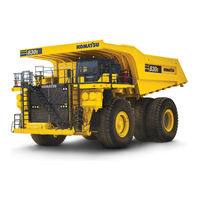
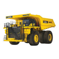
Komatsu 830E Manuals
Manuals and User Guides for Komatsu 830E. We have
2
Komatsu 830E manuals available for free PDF download: Shop Manual, Brochure
KOMATSU 830E Shop Manual (783 pages)
DUMP TRUCK
Brand:
KOMATSU
| Category:
Trucks
| Size: 13.21 MB
Table of Contents
Standard Charts and Tables
55
A00032 Introduction a
5
Table of Contents
55
Table V
58
Table VI
58
Table IX
58
Table X
58
Table XI
59
Section B Structures Index
81
Structural Components
83
Ladders
83
Right Hand Deck
84
Installation
84
Removal
84
Center and Left Hand Deck Components
85
Fuel Tank
86
Installation
86
Removal
86
Dump Body
87
Removal
87
Installation
88
Body Pads
89
Adjustment
90
Body Guide
90
Body-Up Retention Cable
90
Body Position Indicator
91
Rock Ejectors
91
Inspection
91
Hoist Limit Switch
91
Body up Switch
91
Section C Engine Index
93
Power Module
95
Preparation
95
Removal
95
Installation
99
Cooling System
101
Cooling System Description
101
Radiator
102
Removal
102
Installation
104
Radiator Filling Procedure
104
Power Train
105
Alternator Removal Procedure
105
Engine/Alternator Mating
107
Measuring Procedure
107
Engine
110
Installation
110
Removal
110
Air Filtration System
111
Air Cleaner
111
General Service Information
111
Operation
111
Main Filter Element
111
Safety Filter Element
112
Air Intake Troubleshooting
113
Air Cleaner Assembly Cleaning
113
Main Filter Element Cleaning
113
Precleaner Section Cleaning
114
Section D Electrical System (24Vdc Non-Propulsion) Index
117
24Vdc Electric Supply System
119
Electrical System Description
119
Troubleshooting
119
Battery Charging System (Niehoff)
121
General Description
121
Troubleshooting Procedures
121
Advanced System Troubleshooting
126
Operation
128
Maintenance
129
Troubleshooting
133
24Vdc Electrical System Components
141
Passenger Seat Base Compartment
141
Components
141
Alarm Indicating Device (Aid) System
144
Battery Equalizer Box
146
Body up Switch
147
Hoist Limit Switch
147
Volt Relay and Diode Boards
148
Circuit Breaker Chart
149
Section E Electrical Propulsion Components Index
155
Electrical Propulsion Components
157
General System Description
157
Control System
157
Computer Description
161
Software
161
2-Digit Display Panel
164
Events
164
Frames
165
Windows
165
Subcode Descriptions (Table II)
166
Table I
171
Portable Test Unit (PTU)
177
Description
177
Software Installation Preparation
178
The Main Menu
180
Configuration (CFG) File Conversion
182
Statex Configuration Files
186
Programming the Truck
197
Download Configuration Files
199
Event Data
201
Table IV
203
Statistical Data
203
Statistical Data Codes - Counters (Table III)
204
Table III
205
Truck Specific Information
214
Temporary Truck Settings
215
Saving Data
216
PTU Abbreviations
217
Miscellaneous Electrical Propulsion Components
218
Alternator
218
Electric Wheel Motors
218
Retarding Grids
218
Cooling Blower Warning System
220
Electrical Control Cabinet
221
Statex III Electrical System Checkout Procedure
229
General Information
231
Communications Port Check
232
PTU Hookup
232
1 SEQUENCE TESTS - (Engine Not Running)
234
Throttle System Check and Adjustment
235
Electronic Throttle System
235
Reverser and Propulsion Contactors Check
241
Retard Contactors Operation Check
243
Ground Fault Sensing Check
243
Ground Fault in Retard Operation Check
243
Override Operation Check
244
Anti-Reversal Function (AR) Check
245
Overspeed Retard Operation Check
245
Hoist Interlock Operation Check
246
Motor Blower Fault Light Operation Check
247
2 Digital Input/Output Signals Tests - Fl275 Card Panel
248
Setup Manual Digital Input/Output Test on PTU
248
Digital Input Checks
249
Digital Output Checks
251
3 Analog Input Signals Tests - Fl275 Card Panel
254
Setup Analog Input Monitor Screen on PTU
254
Analog Input Checks
255
Frequency Input Checks
262
4 Speed Event Checks
264
Other Speed Events Checks
265
5 Retard Speed Control System Check
267
Overspeed Pickup and Dropout Check
267
Retard Pot Maximum Setting Check
268
Retard Pot Minimum Setting Check
268
Accelerator Pedal Override of Retard Speed Control
268
6 Load Test Using Truck Retard Grids
269
7 Motor Field Current Check in Retarding
271
8 Miscellaneous Component Test and Adjustment
272
Brake System Interlocks Check
272
Blower Loss Pressure Switch Adjustment
273
SYNC Transformer Checkout
273
Power Contactor Position Sensor Adjustment
273
Battery Boost Adjustment
274
Isolation Amplifier & Voltage Module Test
274
Voltage Measuring Module Test (VMM1 & VMM2)
274
Motor Rotation Test
275
Ground Fault Checks
276
9 Optional Payload Meter (Plm II) Check-Out Procedure
277
10 Miscellaneous Charts
278
Wheel Motor Gear Ratios
278
Maximum Allowable Truck Speeds
279
Engine Options
280
Section G Drive Axle, Spindle and Wheels Index
281
Tires and Rims
283
Front Tires and Rims
283
Removal
283
Installation
284
Rear Tires and Rims
285
Removal
285
Installation
286
Rim
287
Rim and Tire Preperation
287
Tire Removal
287
Lubricants
288
Tire Installation
288
Wheel Hub and Spindle Assembly
291
Removal
291
Spindle Pusher Tool Usage
292
Installation
293
Cleaning and Inspection
295
Disassembly
295
Assembly
296
Wheel Bearing Adjustment
298
Wheel Bearing Adjustment (Tire Mounted)
298
Steering Cylinders and Tie Rod
300
Spherical Bearing Wear Limits
300
Bearing Replacement
301
Installation
301
Removal
301
Toe-In Adjustment
303
Rear Axle Housing Attachment
305
Pivot Pin
305
Installation
305
Removal
305
Pivot Eye Bearing
306
Assembly
306
Disassembly
306
Anti-Sway Bar
308
Assembly
308
Cleaning and Inspection
308
Disassembly
308
Installation
308
Removal
308
Rear Axle Housing
309
Removal
309
Installation
309
Wheel Motor
309
Cleaning and Inspection
310
Installation
310
Section H ® Hydrair II Suspensions Index
311
Front Suspension
313
Removal
313
Installation
314
Turn-Of-The-Nut" Tightening Procedure
316
Bearing Structure Removal
317
Bearing Structure Installation
317
Major Suspension Rebuild
318
Disassembly
318
Assembly
319
Pressure Test
320
Rear Suspension
321
Removal
321
Installation
323
Disassembly
325
Assembly
325
Pressure Test
326
Section J Brake Circuit Index
335
Brake Circuit
337
Service Brake Circuit Operation
337
Secondary Braking and Automatic Apply
339
Parking Brake Circuit
339
Brake Lock Circuit
340
Warning Circuit
340
Brake Circuit Component Service
343
Brake Valve
343
Removal
343
Installation
345
Disassembly
346
Assembly
348
Cleaning and Inspection
348
Differential Pressure Switch
351
Valve Bench Test and Adjustment
352
Installation of Brake Pedal Actuator to Brake Valve
354
Hydraulic Brake Accumulators
357
Parking Brake
364
Brake Circuit Checkout Procedure
372
Rockwell Wheel Speed Front Disc Brakes
373
Brake Caliper
373
Brake Lining
377
Brake Bleeding Procedure
379
Rockwell Armature Speed Rear Disc Brakes
381
Rear Brakes
381
Caliper, Disc and Parking Brake
381
Bench Test
392
Brake Lining
393
Brake Bleeding Procedure
398
Rockwell Disc Parking Brake
399
Park Brake Caliper
399
Removal
399
Installation
400
Parking Brake Adjustment
400
Cleaning and Inspection
402
Park Brake Caliper Disassembly
402
Park Brake Caliper Assembly
403
Park Brake Lining
404
Park Brake Burnish Procedure
404
Brake Bleeding Procedure
404
Section L Hydraulic System Index
405
Hydraulic System
407
Component Description
408
Hydraulic System Component Repair
411
Hoist Pump
411
Hydraulic Tank
411
Hydraulic Tank Strainers
423
Hoist Circuit Filters
424
Steering Circuit
427
Steering Circuit Operation
427
Component Description
428
Flow Amplifier
428
Steering Control Unit
428
Bleed down Manifold
438
Accumulators
439
Steering/Brake Pump
439
Steering Circuit Component Repair
445
Bleed down Manifold
445
Accumulator
446
Steering Accumulator Charging Procedure
450
Flow Amplifier
451
Steering Control Unit
456
Steering Cylinder
462
Steering Circuit Filter
463
Steering and Brake Pump
465
Hoist Circuit
477
Hoist Circuit Operation
477
Component Description
478
High Pressure Filters
478
Hoist Pump
478
Hoist Valve
493
Hoist Pilot Valve
499
Pilot Operated Check Valve
502
Disabled Truck Dumping Procedure
511
Hydraulic Checkout Procedure
513
Steering and Brake Pump
513
Bleeddown Manifold
514
Shock & Suction Valves
515
Leakage Tests
516
Troubleshooting Chart
518
Steering Circuit
518
Steering Pump
520
Counterbalance Valve
527
Hydraulic System Flushing Procedure
530
Inspection and Maintenance
533
Operation
533
Recharging Procedures
534
Alternator and Wheelmotor Cooling Air Filter System (M04002)
535
Pump
535
System Adjustment
535
Blower Drive Motor
538
Blower Bearing Repair
541
Air Cleaner
542
Wiggins Quick Fill Fuel System (M05002)
543
Fuel Receiver
543
Tank Breather Valve
544
Buckeye Quick Fill Fuel System (M05003)
547
Tank Breather Valve
547
Fuel Receiver
548
Engine Coolant Heater (M07001)
549
Heating Element
549
Thermostat
550
Special Tools
551
Environmental Impact
557
Principles of Refrigeration
558
Air Conditioner System Components
560
Electrical Circuit
562
System Servicing
564
Service Tools and Equipment
567
Manifold Gauge Set
569
System Performance Test
572
System Leak Testing
573
System Repair
574
Evacuating the System
581
Troubleshooting
583
Preventive Maintenance Schedule for AC System
591
Radiator Shutters
593
Section N Operator's Cab Index
661
Truck Cab
663
Description
663
Removal
664
Installation
665
Cab Door
666
Door Adjustment
666
Installation
666
Removal
666
Door Handle Plunger Adjustment
668
Replace Door Glass
669
Replace Door Window Regulator
673
Adhesive-Bonded Windows
675
Glass Replacement
675
Cab Components
679
Windshield Wiper
679
Windshield Washer
681
Operator Comfort
683
Operator Seat
683
Adjustment
683
Heater Components
685
Filter
686
Operator Controls and Equipment
689
Steering Wheel and Controls
690
Steering Column
690
Pedal Controls
692
Overhead Controls, Gauges, Etc
693
Center Console Controls
694
Hoist Control Lever
694
Instrument Panel
699
Section P Lubrication and Service Index
711
Service Capacities
713
Radiator Filling Procedure
714
HOUR (Daily) Lubrication and Maintenance Checks
716
HOUR Lubrication and Maintenance Checks
716
HOUR Lubrication and Maintenance Checks
719
HOUR Lubrication and Maintenance Checks
720
1000 HOUR Lubrication and Maintenance Checks
723
HOUR Lubrication and Maintenance Checks
725
Automatic Lubrication System
727
General Description
727
System Components
729
System Operation
730
Injector Operation
732
General Instructions
733
System Checkout
736
Pump Rebuild
737
System Troubleshooting Chart
740
Alphabetical Index
749
Advertisement
Komatsu 830E Brochure (4 pages)
ELECTRIC DRIVE TRUCK
Brand:
Komatsu
| Category:
Trucks
| Size: 0.57 MB
Advertisement
Related Products
Komatsu 830E-1AC
Komatsu 830E-AC
Komatsu 83001
Komatsu 85001
Komatsu 860E-1KT
Komatsu 82E Series
Komatsu 85113
Komatsu 80888
Komatsu 81258
Komatsu 81261
Komatsu Categories
Excavators
Compact Loader
Trucks
Construction Equipment
Tractor
More Komatsu Manuals
Login
Sign In
OR
Sign in with Facebook
Sign in with Google
Upload manual
Upload from disk
Upload from URL