Sign In
Upload
Manuals
Brands
Kollmorgen Manuals
DC Drives
AKD
Kollmorgen AKD Manuals
Manuals and User Guides for Kollmorgen AKD. We have
9
Kollmorgen AKD manuals available for free PDF download: User Manual, Installation Manual, Manual, Accessories Manual, Fault Card
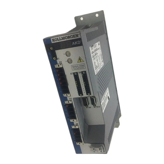
Kollmorgen AKD User Manual (506 pages)
Brand:
Kollmorgen
| Category:
Controller
| Size: 1.86 MB
Table of Contents
Table of Contents
4
1 About this User Guide
16
2 Program View
17
Toolbar Options
17
New
17
Save / Save as
17
Open
18
Edit Parameters Section
18
Compile / Download / Run
18
Continue / Pause / Stop
18
Debug
18
View
19
Format Document
19
Insert Code Snippet
19
Upload
19
Lock
19
3 AKD BASIC Language
20
AKD BASIC Program Structure
20
Local Variables
20
Global Variables
20
Program Sections
21
Program Template
21
Setup Parameter Definitions
21
Global Variables, Constants, and Aliases
22
Variable Definitions
22
Constant Definitions
22
Alias Definitions
23
Main Program, Subroutines, Functions & Interrupt Handlers
23
Main Definitions
23
Subroutine Definition
24
Function Definition
25
Interrupt Handler Definition
25
Language Definition
26
Lexical Conventions
26
Identifiers
26
Data Types
26
Literal Constants
27
Decimal Integer Constants
27
Hexadecimal Constants
27
Floating-Point Constants
27
Statements
28
Alias
28
Call
28
Cls
28
Const
28
DIM
29
Exit
29
For
29
Function
30
Goto
30
Include
31
Input
31
Interrupt
31
Move.abort
31
Move.goabs
31
Move.gohome
31
Move.gorel
32
Move.goupdate
32
Move.govel
32
On Error Goto
32
Pause( )
33
Print
33
Example
33
VM.restart
33
Select Case
33
Static
34
Stop
34
Sub
34
Swap
35
When
35
Built-In Functions
35
Parameters and Commands
36
Expressions
37
Arithmetic Expressions
37
Numeric Operators
37
Logical Operators
37
String Operators
38
Example
38
Function Invocation
38
Include
38
Arrays and Function Parameter Lists
39
Optimizations
39
Modbus TCP/IP
41
Modbus Parameter Table
41
Modbus Register and Data Types
41
User Created Variables with Assigned Modbus Address Numbers
41
Drive Fault Table
42
Drive Parameter Scaling over Modbus
42
Special Modbus AKD Parameters
42
Modbus Dynamic Mapping
43
Cam Profiling
43
Procedure
43
Related Variables
43
Cam Wizard
44
Example
45
Program
45
Virtual Encoder (Virtual Master)
46
Move Parameters
47
Move Statements
47
Other Variables
47
4 Quick Reference: Parameters, Functions, Operators
48
AKD Parameters and Commands
48
AKD BASIC Parameters and Commands
55
5 AKD BASIC Functions
63
Abs()
64
Asc()
65
Atan()
66
Chr$()
67
Cint()
68
Cos()
69
Exp()
70
Fix()
71
Hex$()
72
Inkey$()
73
Instr()
74
Int()
75
Lcase$()
76
Left$()
77
Len()
78
Log()
79
Log10()
80
Ltrim$()
81
MID
82
Oct$()
83
Right$()
84
Rtrim$()
85
Sgn()
86
Sin()
87
Space$()
88
Sqr()
89
Str$()
90
Exit
104
For...next
105
Function
106
Goto
107
If...then...else
108
Input
109
On Error Goto
110
Pause()
112
Print
113
Restart
114
Select Case
115
Static
116
Stop
117
Sub...end Sub
118
Swap
119
While...wend
120
Operators
121
Mod
122
AIN Parameters
123
Ain.cutoff
124
Ain.deadband
125
Ain.deadbandmode
127
Ain.iscale
129
Ain.mode
130
Ain.offset
131
Ain.pscale
132
Ain.value
134
Ain.vscale
135
Ain.zero
137
AOUT Parameters
139
Aout.cutoff
140
Aout.debugaddr
141
Aout.debugdatatype
142
Aout.debugscale
143
Aout.iscale
144
Aout.mode
145
Aout.offset
146
Aout.pscale
147
Aout.value
149
Aout.valueu
150
Aout.vscale
151
CAM Parameters
152
Cam.activate
153
Cam.addpoint
155
Cam.correctdir
157
Cam.create
158
Cam.master
160
Cam.masterpos
161
Cam.slaveoffset
162
Camvm.dir
163
Camvm.freq
164
Camvm.gorel
165
Camvm.goupdate
166
Camvm.govel
167
Camvm.moving
168
Camvm.position
169
Camvm.relativedist
170
Camvm.stop
171
CAP Parameters
172
Cap0.Edge, Cap1.Edge
173
Cap0.En, Cap1.En
174
Cap0.Event, Cap1.Event
175
Cap0.Filter, Cap1.Filter
178
Cap0.Mode, Cap1.Mode
179
Cap0.Plfb, Cap1.Plfb
180
Cap0.Preedge, Cap1.Preedge
181
Cap0.Prefilter, Cap1.Prefilter
182
Cap0.Preselect, Cap1.Preselect
183
Cap0.State, Cap1.State
184
Cap0.T, Cap1.T
185
Cap0.Trigger, Cap1.Trigger
186
CS Parameters
188
Cs.dec
189
Cs.state
190
Cs.to
191
Cs.vthresh
192
DIN Parameters
193
Din.rotary
194
Din.states
195
Din1.Filter to Din7.Filter
196
DIN1.INV to DIN7.INV
197
DIN1.MODE to DIN19.MODE
198
Din1.State to Din7.State
200
DIN9.STATE to DIN11.STATE
201
DIO Parameters
202
DIO9.INV to DIO11.INV
203
DIO9.DIR to DIO11.DIR
204
DOUT Parameters
205
Dout.relaymode
206
Dout.states
207
DOUT8.MODE to DOUT11.MODE
208
Dout1.Param and Dout2.Param
209
Dout1.State and Dout2.State
210
Dout1.Stateu and Dout2.Stateu
211
DOUT9.STATE to DOUT11.STATE
212
DOUT9.STATEU to DOUT11.STATEU
213
DRV Parameters
214
Drv.acc
215
Drv.active
217
Drv.blinkdisplay
218
Drv.clrfaulthist
219
Drv.clrfaults
220
Drv.cmdsource
221
Drv.dbilimit
222
Drv.dec
223
Drv.dir
224
Drv.dis
226
Drv.dissources
227
Drv.disto
228
Drv.emuedir
229
Drv.emuemode
230
Drv.emuemturn
232
Drv.emueres
233
Drv.emuezoffset
234
Drv.en
235
DRV.FAULT1 to DRV.FAULT10
236
Drv.handwheel
237
Drv.handwheelsrc
238
Drv.hwenable
239
Drv.icont
240
Drv.ipeak
241
Drv.name
242
Drv.nvload
243
Drv.nvsave
244
Drv.opmode
245
Drv.rstvar
246
Drv.setupreqbits
247
Drv.stop
248
Drv.swenable
249
Drv.time
250
DRV.WARNING1 to DRV.WARNING10
251
EGEAR Parameters
252
Egear.acclimit
253
Egear.declimit
254
Egear.error
255
Egear.lock
256
Egear.on
257
Egear.pulsesin
258
Egear.pulseout
259
Egear.ratio
260
Egear.type
261
EXTENCODER Parameters
262
Extencoder.freq
263
Extencoder.position
264
Extencoder.posmodulo
265
FAULT Parameters
266
Faultx.action
267
FB1 Parameters
268
Fb1.Bissbits
269
Fb1.Encres
270
Fb1.Hallstate
271
Fb1.Hallstateu
272
Fb1.Hallstatev
273
Fb1.Hallstatew
274
Fb1.Identified
275
Fb1.Initsigned
276
Fb1.Mechpos
277
Fb1.Memdump
278
Fb1.Memver
279
Fb1.Origin
280
Fb1.P
282
Fb1.Pdir
283
Fb1.Poffset
284
Fb1.Poles
285
Fb1.Pscale
286
Fb1.Punit
287
Fb1.Select
288
FB2 Parameters
290
Fb2.Encres
291
Fb2.Mode
292
Fb2.P
293
Fb2P.dir
294
Fb2.Poffset
294
Fb2.Punit
295
Fb2.Source
296
FB3 Parameters
297
Fb3.Mode
298
Fb3.Poffset
299
Fb3.Punit
300
HWLS Parameters
301
Hwls.negstate
302
Hwls.posstate
303
IL Parameters
304
Il.busff
305
Il.CMD
306
Il.cmdu
307
Il.dfoldt
308
Il.difold
309
Il.fb
310
Il.ff
311
Il.foldfthresh
312
Il.foldwthresh
313
Il.ifold
314
Il.iufb
315
Il.ivfb
316
Il.kp
317
Il.kpdratio
318
Il.limitn
319
Il.limitp
320
Il.mfoldd
321
Il.mfoldr
322
Il.mfoldt
323
Il.mifold
324
Il.VCMD
325
Il.vufb
326
Il.vvfb
327
INTR Parameters
328
Interrupt {Source
329
Interrupt
332
LOAD Parameters
333
Load.inertia
334
MODBUS Paramters
335
Modbus.readfloat
336
Modbus.writefloat
337
MOTOR Parameters
338
Motor.brake
339
Motor.brakeimm
340
Motor.brakerls
341
Motor.icont
342
Motor.inertia
343
Motor.ipeak
344
Motor.ke
345
Motor.kt
346
Motor.lqll
347
Motor.name
348
Motor.phase
349
Motor.pitch
350
Motor.poles
351
Motor.r
352
Motor.tbrakeapp
353
Motor.tbrakerls
354
Motor.temp
355
Motor.tempfault
356
Motor.tempwarn
357
Motor.type
358
Motor.voltmax
359
MOVE Parameters
360
Move.abort
361
Move.acc
362
Move.dec
364
Move.dir
366
Move.dwelltime
367
Move.goabs
368
Move.gohome
369
Move.gorel
370
Move.goupdate
371
Move.govel
372
Move.inposition
373
Move.inposlimit
374
Move.moving
375
Move.poscommand
376
Move.relativedist
377
Move.runspeed
378
Move.scurvetime
379
Move.targetpos
380
PL Parameters
381
Pl.CMD
382
Pl.err
383
Pl.errfthresh
384
Pl.errmode
386
Pl.errwthresh
388
Pl.fb
390
Pl.fbsource
391
Pl.intinmax
392
Pl.intoutmax
394
Pl.ki
396
Pl.kp
397
Pl.modp1
398
Pl.modp2
399
Pl.modpdir
400
Pl.modpen
401
PLS Parameters
402
Pls.en
403
Pls.mode
404
Pls.p1 to Pls.p8
405
Pls.reset
406
Pls.state
407
Pls.t1 to Pls.t8
408
Pls.units
409
Pls.width1 to Pls.width8
411
REC Parameters
413
Rec.active
413
Rec.done
414
Rec.off
415
Rec.trig
416
REGEN Parameters
417
Regen.power
418
Regen.rext
419
Regen.text
420
Regen.type
421
Regen.wattext
422
STO Parameters
423
Sto.state
424
SWLS Parameters
425
Swls.en
426
Swls.limit0
427
Swls.limit1
428
Swls.state
429
UNIT Parameters
430
Unit.acclinear
431
Unit.accrotary
432
Unit.label
433
Unit.pin
434
Unit.plinear
435
Unit.pout
436
Unit.protary
437
Unit.vlinear
438
Unit.vrotary
439
VBUS Parameters
440
Vbus.ovfthresh
441
Vbus.ovwthresh
442
Vbus.rmslimit
443
Vbus.uvfthresh
444
Vbus.uvmode
445
Vbus.uvwthresh
446
Vbus.value
447
VL Parameters
448
Vl.arpf1 to Vl.arpf4
449
Vl.arpq1 to Vl.arpq4
451
Vl.artype1 to Vl.artype4
453
Vl.arzf1 to Vl.arzf4
454
Vl.arzq1 to Vl.arzq4
456
Vl.busff
458
Vl.CMD
459
Vl.cmdu
460
Vl.err
461
Vl.fb
462
Vl.fbfilter
463
Vl.fbsource
464
Vl.fbunfiltered
465
Vl.ff
466
Vl.genmode
467
Vl.kbusff
468
Vl.ki
469
Vl.kp
470
Vl.kvff
471
Vl.limitn
472
Vl.limitp
473
Vl.lmjr
474
Vl.thresh
475
VM Parameters
477
VM.autostart
478
VM.err
479
VM.intrtimer
481
VM.restart
482
WHEN Parameters
483
When
484
When.drvhandwheel
486
When.drvtime
487
When.fb1Mechpos
488
When.plcmd
489
When.plfb
490
WS Parameters
491
Ws.arm
492
Ws.disarm
493
Ws.distmax
494
Ws.distmin
495
Ws.imax
496
Ws.mode
497
Ws.numloops
498
Ws.state
499
Ws.t
500
Ws.tdelay1
501
Ws.tdelay2
502
Ws.tdelay3
503
Ws.vthresh
504
Advertisement
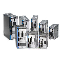
Kollmorgen AKD Installation Manual (196 pages)
Brand:
Kollmorgen
| Category:
DC Drives
| Size: 11.67 MB
Table of Contents
Table of Contents
3
Digital Inputs 3 to
7
2 General
9
2 General
10
1 Table of Contents
10
About this Manual
10
Using the PDF Format
10
Notes for the Printed Edition (Paper Version)
10
Symbols Used
11
Abbreviations Used
12
Standards Used
13
3 Safety
14
You Should Pay Attention to this
15
Use as Directed
17
Prohibited Use
17
Handling
18
Packaging
18
Storage
18
Transport
18
Maintenance and Cleaning
19
Repair and Disposal
19
Uninstalling
19
4 Approvals
20
Conformance with Ul/Cul
21
UL Markings
21
CE Conformance
22
European Directives and Standards for the Machine Builder
23
EC Declaration of Conformity
24
Safe Torque off (STO)
25
5 Package
26
Package Supplied
27
Nameplate
27
Part Number Scheme
28
6 Technical Description and Data
29
The AKD Family of Digital Drives
30
Ambient Conditions, Ventilation, and Mounting Position
32
Mechanical Data
32
Inputs/Outputs
33
Electrical Data AKD-Xzzz06
34
Electrical Data AKD-Xzzz07
35
Performance Data
36
Recommended Tightening Torques
36
Fusing
37
External Power Supply Fusing
37
External 24 V Supply Fusing
37
External Regen Resistor Fusing
37
Grounding System
37
Connectors
38
Cable and Wire Requirements
39
General
39
Cable Cross Sections and Requirements
39
Dynamic Braking
40
Regen Circuit
40
Functional Description
40
Technical Data for AKD-Xzzz06
41
Technical Data for AKD-Xzzz07
42
Switch-On and Switch-Off Behavior
43
Switch-On Behavior in Standard Operation
44
Switch-Off Behavior
45
Switch-Off Behavior Using the DRV.DIS Command
45
Switch-Off Behavior Using a Digital Input (Controlled Stop)
46
Switch-Off Behavior Using HW Enable Input (Uncontrolled Stop)
46
Switch-Off Behavior in the Event of a Fault
47
Stop / Emergency Stop / Emergency off
50
Stop
50
Emergency Stop
51
Emergency off
51
Safe Torque off (STO)
52
Safety Characteristic Data
52
Use as Directed
52
Prohibited Use
52
Safety Instructions
53
Technical Data and Pinning
54
Enclosure, Wiring
54
Functional Description
54
Functional Test
55
Signal Diagram (Sequence)
55
Control Circuit (Example)
56
Mains Supply Circuit (Example)
57
Shock-Hazard Protection
58
Leakage Current
58
Residual Current Protective Device (RCD)
58
Isolating Transformers
58
7 Mechanical Installation
59
Important Notes
60
Guide to Mechanical Installation
60
Mechanical Drawings Standard Width
61
Control Cabinet Layout AKD-Xzzz06, Standard Width
61
Control Cabinet Layout AKD-Xzzz07, Standard Width
62
Dimensions AKD-Xzzz06, Standard Width
63
Dimensions AKD-Xzzz07, Standard Width
64
Mechanical Drawings Extended Width
65
Control Cabinet Layout, Example with AKD-M00306
65
Control Cabinet Layout, Example with AKD-M00307
66
Kollmorgen™ | May
66
Dimensions AKD-Xzzz06, Extended Width
67
Dimensions AKD-Xzzz07, Extended Width
68
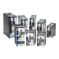
Kollmorgen AKD User Manual (162 pages)
CAN-BUS Communication
Brand:
Kollmorgen
| Category:
Servo Drives
| Size: 1.6 MB
Table of Contents
1 Table of Contents
3
2 General
9
About this Manual
10
Target Group
10
Symbols Used
11
Abbreviations Used
12
3 Safety
13
Safety Instructions
14
Use as Directed
14
Prohibited Use
14
4 Installation and Setup
15
Safety Instructions
16
CAN-Bus Interface (X12/X13)
17
CAN-Bus Activation with AKD-CC Models
18
Baudrate for CAN-Bus
19
Node Address for CAN-Bus
20
CAN-Bus Termination
20
CAN-Bus Cable
20
CAN-Bus Wiring
21
Guide to Setup
22
5 Canopen Basics
23
Basic Features Implemented by Canopen
24
Setup and General Functions
24
Positioning Functions
24
Data Transfer Functions
24
Transmission Rate and Procedure
24
Response to BUSOFF Communication Faults
25
Important Configuration Parameters
25
6 Canopen Communication Profile
26
General Description of CAN
27
Construction of the Communication Object Identifier
28
Definition of the Used Data Types
29
Basic Data Types
29
Unsigned Integer
29
Signed Integer
30
Mixed Data Types
30
Extended Data Types
31
Octet String
31
Visible String
31
Communication Objects
31
Network Management Objects (NMT)
32
Synchronization Object (SYNC)
32
Time-Stamp Object (TIME)
32
Emergency Object (EMCY)
33
Application of the Emergency Object
33
Composition of the Emergency Object
33
Service Data Objects (SDO)
34
Composition of the Service Data Object
34
Initiate SDO Download Protocol
36
Download SDO Segment Protocol
36
Initiate SDO Upload Protocol
36
Upload SDO Segment Protocol
36
Abort SDO Protocol
36
Process Data Object (PDO)
37
Transmission Modes
38
Trigger Modes
38
Nodeguard
39
Heartbeat
40
7 Canopen Drive Profile
41
Canopen Emergency Messages and Error Codes
42
General Definitions
46
General Objects
46
Object 1000H: Device Type (DS301)
46
Object 1001H: Error Register (DS301)
47
Object 1002H: Manufacturer Status Register (DS301)
48
Object 1003H: Predefined Error Field (DS301)
49
Object 1005H: COB-ID of the SYNC Message (DS301)
50
Object 1006H: Communication Cycle Period (DS301)
50
Object 1008H: Manufacturer Device Name (DS301)
51
Object 1009H: Manufacturer Hardware Version
51
Object 100Ah: Manufacturer Software Version (DS301)
51
Object 100Ch: Guard Time (Ds301)Response Monitoring
52
Object 100Dh: Lifetime Factor (DS301)
52
Object 1010H: Store Parameters (DS301)
53
Object 1011H: Restore Default Parameters DS301
54
Object 1014H: COB-ID for Emergency Message (DS301)
55
Object 1016H: Consumer Heartbeat Time
55
Object 1017H: Producer Heartbeat Time
56
Object 1018H: Identity Object (DS301)
56
Object 1026H: os Prompt
58
Manufacturer Specific Objects
59
Object 2014-2017H: 1St-4Th Mask 1 to 4 for Transmit-PDO
59
Object 2018H: Firmware Version
60
Object 2026H: ASCII Channel
61
Object 20A0H: Latch Position 1, Positive Edge
62
Object 20A1H: Latch Position 1, Negative Edge
62
Object 20A2H: Latch Position 2, Positive Edge
62
Object 20A3H: Latch Position 2, Negative Edge
63
Object 20A4H: Latch Control Register
63
Kollmorgen™ | November
64
Object 20A5H: Latch Status Register
64
Object 20A6H: Latch Position 1, Positive or Negative Edge
64
Object 20B8H: Reset of Changed Input Information
65
Object 345Ah: Brake Control
66
Object 3474H: Parameters for Digital Inputs
68
Object 3475H: Parameters for Digital Outputs
69
Object 3496H: Fieldbus Synchronization Parameters
70
Object 60B8H: Touch Probe Function
72
Profile Specific Objects
72
Object 60B9H: Touch Probe Status
73
Object 60Bah: Touch Probe 1 Positive Edge
74
Object 60Bbh: Touch Probe 1 Negative Edge
74
Object 60Bch: Touch Probe 2 Positive Edge
74
Object 60Bdh: Touch Probe 2 Negative Edge
75
Object 60D0H: Touch Probe Source
75
Object 60Fdh: Digital Inputs (DS402)
76
Object 60Feh: Digital Outputs (DS402)
77
Object 6502H: Supported Drive Modes (DS402)
78
PDO Configuration
79
Objects 1400-1403H: 1St - 4Th RXPDO Communication Parameter (DS301)
80
Receive Pdos (RXPDO)
80
Objects 1600-1603H: 1St - 4Th RXPDO Mapping Parameter (DS301)
81
Default RXPDO Definition
82
Objects 1800-1803H: 1St - 4Th TXPDO Communication Parameter (DS301)
83
Transmit Pdos (TXPDO)
83
Objects 1A00-1A03H: 1St - 4Th TXPDO Mapping Parameter (DS301)
85
Default TXPDO Definition
86
Device Control (DC)
87
Status Machine (DS402)
87
States of the Status Machine
88
Transitions of the Status Machine
89
Object 6040H: Control Word (DS402)
90
Object Description
90
Object 6041H: Status Word (DS402)
91
Object 6060H: Modes of Operation (DS402)
93
Object 6061H: Modes of Operation Display (DS402)
94
Factor Groups (Fg) (DS402)
94
Factors
94
General Information
94
Relationship between Physical and Internal Units
94
Object 204Ch: PV Scaling Factor
95
Objects for Velocity Scaling
95
Object 608Fh: Position Encoder Resolution (DS402)
96
Objects for Position Calculation
96
Object 6091H: Gear Ratio (DS402)
97
Object 6092H: Feed Constant (DS402)
98
Advertisement
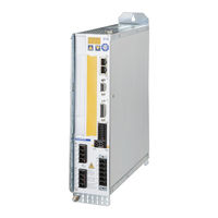
Kollmorgen AKD Manual (102 pages)
Using AKD EtherNet/IP with RSLogix
Brand:
Kollmorgen
| Category:
Servo Drives
| Size: 0.94 MB
Table of Contents
1 Table of Contents
3
2 Introduction
7
Controller Support
7
Add-On Instructions
7
3 AKD Installation and Setup
9
4 Quick Start with the AKD Sample Project
10
5 Adding AKD Support to a New or Existing Project
11
Adding the Ethernet IO Module for AKD Communication
11
Importing the AKD Add-On Instructions to a Project
14
Using the AKD Add-On Instructions in a Project
20
Reading and Writing Drive Parameters
24
Read Drive Parameter
24
Write Drive Parameter
26
Execute Drive Command Parameter
26
6 AKD Instructions
28
Motion Axis Drive Communication (Akd_Drive)
28
Description
28
Operands
28
AKD_DRIVE Structure
28
Execution
28
Changes to Axis Status Bits
29
Motion Axis on (Akd_Enable)
30
Description
30
Operands
30
AKD_ENABLE Structure
30
Execution
30
Changes to Axis Status Bits
31
Motion Axis off (Akd_Disable)
32
Description
32
Operands
32
AKD_DISABLE Structure
32
Execution
32
Changes to Axis Status Bits
33
Motion Axis Home (Akd_Home)
33
Description
33
Operands
33
AKD_HOME Structure
33
Execution
34
Changes to Axis Status Bits
34
Motion Axis Jog (Akd_Jog)
34
Description
34
Operands
35
AKD_JOG Structure
35
Programming Guidelines
35
Execution
35
Changes to Axis Status Bits
36
Motion Axis Move (Akd_Move)
37
Description
37
Operands
37
AKD_MOVE Structure
37
Programming Guidelines
38
Choosing a Move Type
38
Execution
38
Changes to Axis Status Bits
38
Description
39
Operands
39
Motion Axis Set Home Mode (Akd_Set_Home_Mode)
39
AKD_SET_HOME_MODE Structure
40
Homing Modes
40
Execution
40
Changes to Axis Status Bit
40
Motion Axis Set Acceleration (Akd_Set_Accel)
41
Description
41
Operands
41
AKD_SET_ACCEL Structure
41
Execution
41
Changes to Axis Status Bits
42
Motion Axis Set Deceleration (Akd_Set_Decel)
43
Description
43
Operands
43
AKD_SET_DECEL Structure
43
Execution
43
Changes to Axis Bits
44
Motion Axis Set Mode (Akd_Set_Mode)
45
Description
45
Operands
45
AKD_SET_MODE Structure
45
Operation Modes
45
Execution
46
Changes to Axis Status Bits
46
Motion Axis Set Position (Akd_Set_Position)
47
Description
47
Operands
47
AKD_SET_POSITION Structure
47
Execution
48
Changes to Axis Status Bits
48
Kollmorgen AKD Accessories Manual (81 pages)
Brand:
Kollmorgen
| Category:
Servo Drives
| Size: 5.61 MB
Table of Contents
1 Table of Contents
3
2 General
6
About this Manual
6
Symbols
6
General Safety Instructions
6
3 Digital Drive Systems
7
Drive System with AKD-X00306 to 02406
7
Drive System with AKD-X00307 to 02407
8
Drive System with AKD-X04807
9
Decentralized Drive System with AKD-C and AKD-N
10
Drive System with AKD2G-Sxx-6Vxxd
11
Drive System with AKD2G-Sxx-7Vxxd
12
Drive System with S701 to 724
13
Drive System with S748 to S772
14
4 Mechanical Tools
15
Safety Instructions
15
Mounting Kit for AKMH Motors
15
Suspension Unit for AKM8 Motors
16
Heat Sink for AKD-N
17
Mounting Clamps for AKD-N
17
5 Input, Output, and Feedback Accessories
18
X9 Screw Terminal Adapter, AKD-X9ADPT
18
Linear Motor Adapter
18
ACI-AKD-A Pinout Drawing
19
ACI-AKD-B Pinout Drawing
19
6 Shielding Accessories
20
Safety Instructions
20
Shield Plates
20
AKD Shield Plates
20
AKD-Z-Zzz06 Shield Plate
20
AKD-Z-00307, AKD-Z-00607, AKD-Z-01207 Shield Plate
21
AKD-Z-02407 Shield Plate
21
Connector Tool for AKD-N
22
Sealing Plugs for AKD-N Connectors
22
AKD, AKD2G and S701 to S724 Shield Clamps (Purchased Separately)
23
S748 to S772 Shield Clamps (Purchased Separately)
23
External Shielding Busbar (Purchased Separately)
24
7 Mating Connectors and Adapters
26
Connectors for AKD-B/P/T/M
26
Connectors for AKD-C
27
Connectors for AKD-N
27
Connectors for AKD2G
28
Smart Feedback Adapter (SFA) for AKD2G
29
8 Mains Chokes
30
Safety Instructions
30
Type Assignment
31
Order Codes
31
Mains Choke 3L
32
9 Mains Filters
33
Safety Instructions
33
Type Assignment
33
Order Codes
34
Mains Filters FN2090
35
Mains Filters 1NF-10
36
Mains Filters FN3288
37
Mains Filters 1NF-20B, 1NF-25
38
Mains Filters 3NF-07
39
10 Capacitor Modules
40
Important Notes
40
Order Codes
41
KCM Module
42
External Regen Resistor BAFP(U)
43
11 Brake/Regeneration Resistors
44
Safety Instructions
44
Type Assignment
45
Order Codes
46
External Regen Resistor BAFP(U)
47
External Regen Resistor BAR(U)
48
External Regen Resistor BAS(U)
49
12 Motor Chokes
50
Shielded Motor Cables
50
Safety Instructions
51
Type Assignment
51
Motor Choke 3YLN-XX
52
Kollmorgen AKD Manual (75 pages)
PROFINET RT Communication
Brand:
Kollmorgen
| Category:
Servo Drives
| Size: 1.38 MB
Table of Contents
1 Table of Contents
3
2 General
5
About this Manual
6
Target Group
6
Symbols Used
7
Abbreviations Used
7
3 Installation and Setup
8
Important Instructions
9
PROFINET Onboard
10
LED Functions
10
Connection Technology
10
Network Connection Examples
10
Guide to Setup
11
Configure IP Address Parameters
12
Dependency Service Channel (Workbench) and PROFINET
14
Reset of IP Address Parameters
14
Setup Step
15
Parameter Configuration with Profidrive over PROFINET IO
18
Parameter Configuration
19
Example for Writing the Operation Mode
20
4 Profinet Io
21
Introduction
22
Restrictions and Requirements
22
Conformance Classes
22
Cycle Time of RT Data
22
Connector
22
Network Topology
22
Modbus
22
5 PROFIDRIVE over PROFINET IO
23
Introduction
24
AKD as Drive Object (DO)
25
General State Machine
26
Control Word Bits (STW1)
27
Status Word Bits (ZSW1)
29
Supported Pnu's
30
Signals
48
Telegram Configuration
48
Drive Inputs Signal
49
Velocity Mode (Application Class 1)
49
Position Mode (Application Class 3)
50
Submode „Program Mode
50
Submode „Manual Data Input (MDI)
51
Homing
53
I/O Telegrams
54
Standard Telegram 9
55
Manufacturer Specific Telegram 350
56
Manufacturer Specific Telegram 353
57
Units
58
Alarms
59
6 PN Parameters
60
Pn.accscaling
61
Pn.posscale
62
Pn.stw1
62
Pn.timeoutfthresh
63
Pn.velscaling
64
Pn.zsw1
65
Kollmorgen AKD Manual (49 pages)
Ethernet/IP Communication
Brand:
Kollmorgen
| Category:
Conference System
| Size: 0.35 MB
Table of Contents
Status Word
2
1 Table of Contents
3
2 About this Manual
5
3 Overview
6
4 AKD Ethernet/Ip Features
7
Supported Features
7
Expected Packet Rate
7
Connection Port
7
Network Topology
7
5 Setup
8
Setting an IP Address in the Drive
8
Controller Setup
8
Setting Expected Packet Rate in the Controller
8
6 Communication Profile
9
Explicit Messaging (On-Demand)
9
Supported Services
9
Supported Objects
9
Data Types
10
Error Codes
10
I/O Assembly Messaging (Cyclic)
10
Controller Configuration
10
Command Assemblies
11
Command Assembly Data Structure
11
Control Word
12
Command Type 0X05 - Torque
12
Command Type 0X06 - Position Move
12
Command Type 0X07 - Jog Move
13
Command Type 0X1B - Set Attribute of Position Controller Object
13
Command Type 0X1F - Read or Write Parameter Value
13
Get Attribute
13
Response Assemblies
14
Response Assemly Data Structure
14
Status Word
14
Response Type 0X05 - Actual Torque
15
Response Type 0X14 - Command/Response Error
15
Data Handshake
16
Velocity Mode
17
Setup Velocity Mode
17
Velocity Moves
17
Position Mode
17
Setup Position Mode
17
Homing
17
Position Moves (Point to Point)
18
Running a Stored Motion Task Sequence
18
Torque
18
Setup Torque Mode
18
Torque Moves
19
Handling Faults
19
Saving to Non-Volatile Memory
19
Kollmorgen AKD Manual (48 pages)
PROFINET RT Communication
Brand:
Kollmorgen
| Category:
Servo Drives
| Size: 0.89 MB
Table of Contents
Table of Contents
3
1 General
5
About this Manual
6
Target Group
6
Symbols Used
7
Abbreviations Used
7
Standard Telegram
7
2 Safety
8
Safety Instructions
9
Use as Directed
9
Prohibited Use
9
Standard Telegram
9
3 Installation and Setup
10
Safety Instructions
11
PROFINET Onboard
12
LED Functions
12
Connection Technology
12
Network Connection Examples
12
Guide to Setup
13
Configure IP Address Parameters
14
Dependency Service Channel (Workbench) and PROFINET
16
Reset of IP Address Parameters
16
Setup Step
17
Parameter Configuration with Profidrive over PROFINET IO
20
Parameter Configuration
21
Example for Writing the Operation Mode
22
4 Profinet Io
23
Introduction
24
Restrictions and Requirements
24
Conformance Classes
24
Cycle Time of RT Data
24
Connector
24
Network Topology
24
5 PROFIDRIVE over PROFINET IO
25
Introduction
26
AKD as Drive Object (DO)
27
General State Machine
28
Control Word Bits (STW1)
29
Status Word Bits (ZSW1)
31
Supported Pnu's
32
Signals
33
Telegram Configuration
33
Velocity Mode (Application Class 1)
34
Position Mode (Application Class 3)
35
Submode „Program Mode
35
Submode „Manual Data Input (MDI)
36
Homing
38
I/O Telegrams
39
Telegram
39
Standard Telegram
39
Manufacturer Specific Telegram 350
40
Units
40
Velocity Units
40
Position Units
40
Acc-/Deceleration Units
40
Current Units
40
Alarms
41
Fault
41
Kollmorgen AKD Fault Card (31 pages)
Brand:
Kollmorgen
| Category:
Servo Drives
| Size: 0.34 MB
Table of Contents
1 Table of Contents
3
2 Fault and Warning Messages
4
Fault & Warning Indicators at the Device
4
Fault & Warning Details with a Connected Device
4
3 Additional Fault Messages AKD-T
28
4 Record of Document Revisions
30
Advertisement
Related Products
Kollmorgen AKD PDMM
Kollmorgen AKD-x00306
Kollmorgen AKD-x00606
Kollmorgen AKD-x01206
Kollmorgen AKD-x02406
Kollmorgen AKD-x00307
Kollmorgen AKD-x00607
Kollmorgen AKD-x01207
Kollmorgen AKD-x02407
Kollmorgen AKD-CC
Kollmorgen Categories
Servo Drives
Amplifier
Touch terminals
DC Drives
Engine
More Kollmorgen Manuals
Login
Sign In
OR
Sign in with Facebook
Sign in with Google
Upload manual
Upload from disk
Upload from URL