Sign In
Upload
Manuals
Brands
Kohler Manuals
Engine
LAMBARDDINI LDW 2204
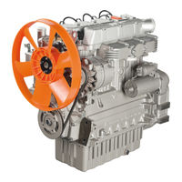
Kohler LAMBARDDINI LDW 2204 Manuals
Manuals and User Guides for Kohler LAMBARDDINI LDW 2204. We have
1
Kohler LAMBARDDINI LDW 2204 manual available for free PDF download: Workshop Manual
Kohler LAMBARDDINI LDW 2204 Workshop Manual (108 pages)
Brand:
Kohler
| Category:
Engine
| Size: 12.11 MB
Table of Contents
General Service Manual Notes
3
Glossary and Terminology
3
Preface
3
Table of Contents
4
General Remarks and Safety Information
8
Safety Regulation
8
1 General Remarks and Safety Information
9
California Proposition 65 WARNING
9
Regulations for Lifting the Engine
9
General Safety During Operating Phases
10
Safety and Enviromental Impact
10
Information and Safety Signals
11
Explanation of the Safety Pictograms that Can be Found on the Engine or in the Workshop Manual
12
Indications Regarding the Points on the Engine Where the Safety Pictograms Are Placed
12
2 Technical Information
14
Manuifacturer and Motor Identification Data
14
Name Plate for EPA Rules Applied on Rocker-Arm Cap
15
Technical Data
16
Possible Causes and Trouble Shooting
18
Performance Diagrams
20
Overall Dimensions
22
3 Maintenance - Prescribed Lubricant - Refilling
28
Extraordinary Maintenance
28
Ordinary Maintenance
28
Routine Engine Maintenance
28
ACEA Regulations - Sequences
29
International Specifications
29
Lubricant
29
SAE Classification
29
Prescribed Lubricant
30
Coolant
31
Fuel Recommendation
31
4 Disassembly/Reassembly
34
Recommendations for Disassembling and Assembling
34
Recommendations for Overhauls and Tuning
34
Dry Air Cleaner
35
Oil-Bath Air Cleaner
35
Oil-Bath Air Cleaner Components
35
Air Filter Clogging Indicator
36
Dry Air Components
36
Cooling Fan
37
Exhaust Manifold
37
Intake Manifold
37
Belt
37
Driving Pulley (2A P.T.O.)
38
Flywheel
38
Tank
38
Rocker Arm Cover for Engines with Recirculating Vent
39
Rocker Arm Cover with Vent into the Air
39
Cylinder Head
40
Rocker Arm Assemly
40
Valve Removal
40
Valve Guides and Cylinder Head
41
Valve Material
41
Valve Spring - Check
41
Valve Spring - Check under Load
41
Oil Seal in the Valves Guides, (Intake and Exhaust)
42
Valve Guide Insertion, after Driving
42
Valve Recess and Sealing Surfaces
43
Valve Seats and Bore
43
Hydraulic Diagram for Feeding the Tappets
44
Hydraulic Tappet Components
44
Hydraulic Tappet Valve Control
44
Precombustion Chamber
44
Hydraulic Tappet Operation
45
Injection Pump Follower
45
Cylinder Roughness
46
Cylinders
46
Piston
46
Piston Availability
46
Piston Rings - Clearance between Grooves
47
Piston Rings - End Gaps
47
Piston Rings - Fitting Sequence
47
Piston Weight
47
Cylinder Head Gasket
48
Cylinder Head Tightening for Engines Without Hydraulic Tappets
48
Piston - Refitting
48
Piston Position and Clearance
48
Assembling and Tightening the Cylinder Head on Engines with Hydraulic Tappets
49
Cylinder Head Tightening Steps
49
Connecting Rod
50
Connecting Rod and Piston Pin
50
Connecting Rod Weights
50
Connecting Rod Alignment
51
Connecting Rod/Piston Assemblies
51
Piston Cooling Sprayer
51
Center Main Bearings
52
Main Bearing Caps Timing Side - Flywheel Side
52
Check Clearance between Main Bearings and Journals
53
Thrust Bearings
53
Crankshaft End Play
54
Thrust Bearing, Oversizes
54
Crankshaft Front and Rear Oil Seal
55
Crankshaft Lubrication Ducts
55
Crankshaft Timing Gear
55
Checking Main Journals and Crank Pins
56
Main Bearing and Connecting Rod Big Bearing Inside Diameter (MM)
56
Main Journal and Connecting Rod Big End Journal Diameter
56
Crankshaft for Engines with Dynamic Equalizer (Only Four-Cylinder Engines)
57
Dynamic Balancer (on Request)
57
Front Cover (after the Serial Number 7366306)
58
Front Cover (before the Serial Number 7366305)
58
Idler Gear and Hub
58
Dimensions for Injection Pump Delivery Control Yoke Adjustement
59
Speed Governor
59
Camshaft Gear - Speed Governor Counter Weights
60
Frame with Idling Speed Governor Spring
60
Speed Governor Counter Springs
60
Camshaft
61
Spring for Extra Fuel Supply at Starting
61
Summary Tables of the Governor Equipment According to the Speed Variation
61
Camshaft Bushing Replacement
62
Camshaft Journals and Bushings in Model LDW 1503 -1603
62
Camshaft Journals and Bushings in Models LDW 2004-2204-2004/T-2204/T
62
Checking Camshaft Bushing Internal Diameter
62
Intake, Exhaust and Injection Cam Height for Engine with Hydraulic Tappets
63
Intake, Exhaust and Injecton Cam Height for Model LDW 1503
63
Camshaft Timing
64
Valve Timing Check
64
Valve Timing Without Considering Timing Marks
64
Engines with Hydraulic Tappets
65
Engines with Mechanical Tappets
65
Camshaft End Play
66
GR 1 and GR 2 Hydraulic Pump 3Rd P.t.o
66
Hydraulic Pump P.t.o
66
5 Turbocharger
68
Turbocharger Components
68
Turbocharger Testing
68
Checking Actuator Setting "Waste Gate
69
6 Lubrication System
70
Oil Filter Cartridge
71
Oil Pressure Adjusting Valve
71
Oil Pump
71
Oil Pump Rotor Clearance
71
Oil Pressure Check
72
Oil Pressure Curve for LDW 1503 - 1603
72
Oil Pressure Curve for LDW 2004 - 2204
72
Oil Pressure Curve for LDW 2004/T - 2204/T
72
Cooling System
74
7 Cooling System
75
Checking for Cooling System Leaks
75
Coolant Circulating Pump
75
Expansion Tank and Cap
75
Thermostat
75
Fuel System
76
8 Fuel System
77
Fuel Feeding Pump
77
Fuel Feeding Pump Drive Rod Protrusion
77
Fuel Filter
77
Electric Fuel Pump (24V)
78
Injection Pump
78
Injection Pump Disassembly
78
How to Reassemble Injection Pump Components
79
How to Remove Injection Pump Feeding Tubes
79
Injection Pump Control Rod
79
Injection Pump Non-Return Valve
79
How to Reassemble Injection Pump Feeding Tubes
80
Injection Pump Delivery Equalization
80
Instrument for Equalizing Injection Pump Delivery Part No. 7104-1460-090
80
Checking Injection Pump Delivery
81
Injection Pump P. No. 6590-249 - Plunger and Barrel Assembly
81
Test Data of Injection Pump
81
Checking Low Pressure Injection Timing for Engines with Hydraulic Tappets
82
Checking Low Pressure Injection Timing for Engines with Mechanical Tappets
83
Injection Timing Correction by Changing the Pad Thickness
83
Injector (Pin Type)
84
Injector Setting
84
9 Electric System
87
Alternator Type Marelli AA 125 R 14V 45A
88
Characteristic Curves for Alternator Type Marelli AA 125 R 14V 45A
88
Alternator Type Marelli AA 125 R 14V 65A
89
Alternator Type Iskra, AAK3139 14V 80A
90
Characteristic Curves for Alternator Type Iskra, AAK3139 14V 80A
90
Alternator Type Iskra, Type AAK3570 28V 35A (for 24 V Outfits)
94
Characteristic Curves for Alternator Type AAK3570 28V 35A (for 24 V Outfits)
94
Advertisement
Advertisement
Related Products
Kohler Lombardini LDW 702
Kohler Lombardini LDW 1003
Kohler Lombardini LDW 1404
Kohler LAMBARDDINI LDW 1503
Kohler LAMBARDDINI LDW 2004
Kohler LAMBARDDINI LDW 2004/T
Kohler LAMBARDDINI LDW 1603
Kohler LAMBARDDINI LDW 2204/T
Kohler Lombardini LDW 502
Kohler Lombardini LDW 492 DCI
Kohler Categories
Plumbing Product
Bathroom Fixtures
Bathtubs
Toilets
Engine
More Kohler Manuals
Login
Sign In
OR
Sign in with Facebook
Sign in with Google
Upload manual
Upload from disk
Upload from URL