Sign In
Upload
Manuals
Brands
KOHLER Manuals
Engine
Courage SV600
KOHLER Courage SV600 Manuals
Manuals and User Guides for KOHLER Courage SV600. We have
8
KOHLER Courage SV600 manuals available for free PDF download: Service Manual, Owner's Manual
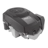
Kohler Courage SV600 Service Manual (133 pages)
VERTICAL CRANKSHAFT
Brand:
Kohler
| Category:
Engine
| Size: 5.14 MB
Table of Contents
Table of Contents
3
Rotating Parts!
5
Hot Parts!
5
Section 1. Safety and General Information
5
Accidental Starts!
5
Explosive Fuel!
6
Flammable Solvents!
6
Lethal Exhaust Gases!
6
Explosive Gas!
6
Engine Identification Numbers
7
Fuel Recommendations
8
Oil Recommendations
8
Oil Type
8
Periodic Maintenance
9
Storage
9
Typical Engine Dimensions
10
General Specifications
11
General Torque Values
17
Oil Drain Plugs Tightening Torque: N-M (English)
17
Torque Conversions
17
Section 2. Tools & Aids
19
Special Tools You Can Make
22
Rocker Arm/Crankshaft Tool
22
Flywheel Holding Tool
22
When Troubles Occur, be Sure to Check the Simple
23
Section 3. Troubleshooting
23
External Engine Inspection
24
Cleaning the Engine
24
Basic Engine Tests
25
Crankcase Vacuum Test
25
Incorrect Vacuum in Crankcase
25
Leakdown Test Results
26
Compression Test
26
Leakdown Test Instructions
26
Cylinder Leakdown Test
26
Air Cleaner Assembly-Exploded View
27
Precleaner Service
27
Section 4. Air Cleaner and Air Intake System
27
Paper Element Service
28
Inspect Air Cleaner Components
28
Bushings in Air Cleaner Base
28
Reassembly
29
Breather Hose
29
Air Intake/Cooling System
30
Fuel Type
31
Gasoline/Alcohol Blends
31
Gasoline/Ether Blends
31
Section 5. Fuel System and Governor
31
Fuel System Troubleshooting Guide
32
Fuel Filter
32
Fuel Line
32
Fuel Pump
32
Troubleshooting–Fuel System
33
Installation
33
Carburetor
33
Pulse Fuel Pump
33
Carburetor Adjustment
34
Troubleshooting: Fuel System
34
Fixed Main Jet Carburetor
34
Low Idle Mixture Adjustment
35
Optimum Low Idle Fuel Setting
35
Low Idle Speed Setting
35
Welch Plug Removal
36
Carburetor-Exploded View
36
Main Fuel Jet Removal
37
Fuel Inlet Seat Removal
37
Choke Shaft Removal
37
Cleaning
37
Inspection
38
Repair
38
Choke Shaft Installation
38
Welch Plug Installation
38
Unitized Throttle and Choke Control
39
High Altitude Operation
39
Fuel Shut-Off Solenoid
39
Throttle Cable Adjustment
40
Speed Control Bracket with Unitized Throttle/Choke Control
40
Adjusting Unitized Throttle/Choke Control
40
Typical Throttle/Choke Controls
40
Alignment Holes in Speed Control Bracket and Throttle Lever. (Later Models)
41
Starting an Engine Equipped with Unitized Throttle and Choke Control
41
Throttle Position for Starting Engine
41
High Speed (RPM) Adjustment
41
Install Separate Control Cables
42
Separate Throttle and Choke Control
42
Choke Adjustment
42
Adjusting High Speed (RPM)
42
Separate Choke and Throttle Cable Controls
43
Alignment Hole in Speed Control Bracket and Throttle Lever (Early Models)
43
Alignment Holes in Speed Control Bracket and Throttle Lever (Later Models)
43
Choke Control Installation
43
Starting an Engine Equipped with Separate Control Cables
44
Changing the High Speed (RPM) on the Engines with Separate Controls (Increase or Decrease RPM)
44
Setting the Low Idle RPM
44
Governed Idle Adjustment
44
Initial Adjustment
45
Governor Gear/Flyweight Assembly
45
Location of Governed Idle Adjusting Screw
45
Operation
45
Tightening Governor Lever Nut
46
Governor Sensitivity Adjustment
46
Early Style Governor Spring Location Chart
46
Later Style Governor Spring Location Chart
47
Oil Recommendations
49
Viscosity Grades Table
49
Check Oil Level
49
Section 6. Lubrication System
49
Dipstick Seated
50
Change Oil and Oil Filter
50
Oil Drain Plug, Oil Filter
50
Lubrication System
50
Oil Level Dipstick
50
Full-Pressure Lubrication System
51
Oil Pump on Intake Cam Shaft (Gerotors Removed from Pump Housing)
51
Oil Filter Location
51
Oil Sentry
51
Tester Locations (some Models)
52
Testing Oil Pressure
52
Testing the Oil Sentry Switch
52
Oil Sentry Pressure Switch Locations
52
Spark Plug Service
53
Section 7. Electrical System and Components
53
Electronic CD Ignition System
55
Capacitive Discharge Ignition Module
56
Troubleshooting and Testing CD Ignition Systems
56
Preliminary Test
56
Testing CD Ignition Module Secondary
57
Ignition Tester
57
CD Ignition System Troubleshooting Guide
57
Battery Charging
58
Battery Maintenance
58
Battery Test
58
Electrical Systems Wiring Diagrams and Battery Charging Systems
58
3 Amp/70 Watt Stator
59
3 Amp Regulated Battery Charging System/70 Watt Lighting
59
Troubleshooting Guide 3 Amp Battery Charging System with 70 Watt Lighting Stator
60
Troubleshooting Guide 3 Amp/70 Watt Braking Stator
61
Battery Charging System 9 or 15 Amp
63
9 Or 15 Amp Stator and Rectifier-Regulator
64
Proper Connection to Test 9 or 15 Amp Charging System
64
Troubleshooting Guide 9 or 15 Amp Regulated Battery Charging System
65
Blade Stop Stator Brake Circuit Wiring Diagram
66
Stator Brake and Relay Harness Connections
67
Troubleshooting Stator Brake System
67
Electric Starters
68
Starting Motor Precautions
68
Troubleshooting Guide-Starting Difficulties
68
Holding Tool and Turning Center Screw (Clockwise) to Remove Retaining Ring
69
Assembling Inner Half of Tool Around the Armature Shaft and Retaining Ring
69
Starter Drive Service
69
Starter Removal and Installation
69
Retaining Ring Installation
70
Assembling Larger Inner Half Around Spring Retainer
70
Starter Disassembly
70
Inertia Drive Electric Starter
70
Brush Replacement
71
Commutator Service
71
Starter Reassembly
71
Oil Drain Location, Oil Filter, and Oil Fill Cap/Dipstick
73
Drain Oil from Crankcase and Remove Oil Filter
73
Typical Disassembly Sequence
73
Section 8. Disassembly
73
Remove Oil Sentry Pressure Switch (on Models so Equipped)
74
Remove Blower Housing
74
Disconnect Spark Plug Lead
74
Remove Rectifier-Regulator
74
Remove Air Cleaner
75
Air Cleaner Components
75
Removing Air Cleaner Base Fasteners
75
Remove External Governor Components, Carburetor, and Fuel Pump
75
Removing Carburetor
76
Removing Heat Deflector Screw and Ground Lead
76
Disconnecting Pulse Line from Fitting
76
Disconnecting Fuel Line from Carburetor
76
Removing Speed Control Bracket from Closure Plate
77
Removing Governor Lever
77
Removing Heat Deflector
77
Disconnecting Governor Spring
77
Removing Lead from Clip (RFI Suppression Equipped Units)
78
Remove Grass Screen, Fan, and Flywheel
78
Remove Ignition Module
78
Removing Insert (some Models)
78
Removing Flywheel Using Puller
79
Remove the Stator
79
Remove the Valve Cover and Cylinder Head
79
Removing Fan and Flywheel Mounting Hardware
79
Loosening Adjustment Set Screw and Nut
80
Removing Cylinder Head Bolts and Washer
80
Removing Cylinder Head and Gasket
80
Removing Drain Back Check Ball from Crankcase (some Models)
80
Disassembling Rocker Arm Components
81
Remove Closure Plate
81
Removing Spark Plug
81
Disassemble Cylinder Head
81
Closure Plate and Gasket Removed from Crankcase
82
Disassemble Closure Plate
82
Removing Oil Passage Cover and Gasket
82
Remove Cam Gears, Cam Shafts, and Oil Pump
82
Removing Cam Levers
83
Removing Exhaust Side Cam Shaft and Slotted Thrust Washer
83
Removing Drain Back Tube (some Models)
83
Pump Outlet Styles
83
Removing Piston and Connecting Rod
84
Separating Oil Pump Assembly from Intake Side Cam Shaft
84
Removing Connecting Rod Cap
84
Intake Cam Shaft and Oil Pump Assembly
84
Remove Piston from Connecting Rod
85
Remove Piston Rings
85
Remove Crankshaft and Balance Weight Assembly
85
Balance Weight Disassembly
86
Removing Crank Gear Key
86
Removing Balance Weight Screw (Guide Shoe Design before Serial No. 3618005213)
86
Removing Balance Weight Screw and Guide Pin (Control Link Design after Serial No. 3618005223)
86
Remove PTO and Flywheel Side Oil Seals
87
Disassembled Balance Weight (Control Link Design after Serial No. 3618005223)
87
Remove Governor Cross Shaft
87
Disassembled Balance Weight (Guide Shoe Design before Serial No. 3618005213)
87
Automatic Compression Release (ACR)
89
ACR Details
89
Section 9. Inspection and Reconditioning
89
Benefits
90
Crankshaft and Crank Gear
90
Crankcase
90
Honing
90
Balance Weight Assembly
91
Measuring Piston-To-Bore Clearance
91
Cylinder Bore Crosshatch after Honing
91
Measuring Balance Weight to Crankshaft Eccentric Ring(S) Clearance
92
Measuring Balance Weight Guide Pin and Guide Shoe-To-Closure Plate Guide Channel Running Clearance
92
Balance Weight-To-Eccentric Clearance
92
Measuring Guide Pin O.D.
93
Measuring Guide Shoe Hole I.D.
93
Flywheel
93
Cylinder Head and Valves
94
Inspection and Service
94
Valve Details
94
Pistons and Rings
97
Valve Guides
97
Lapping Valves
97
Valve Seat Inserts
97
Common Types of Piston and Ring Damage
98
Some Important Points to Remember When Servicing Piston Rings
99
Measuring Piston Ring End Gap
99
Measuring Piston Ring Side Clearance
99
Install Piston Rings
99
Torque Sequence for Passage Cover
100
Closure Plate and Passage Cover
100
Oil Pump Assembly and Pressure Relief Valve
100
Connecting Rods
100
Governor Gear and Shaft
101
Procedure to Remove Governor Shaft
101
Procedure to Install Governor Shaft
101
Governor Shaft Press Depth
101
Typical Reassembly Sequence
103
Install PTO Side Oil Seal
103
Section 10. Reassembly
103
Install Oil Pump Assembly and Intake Cam Shaft
104
Securing Governor Shaft
104
Install Governor Cross Shaft
104
PTO Seal Depth Details
104
Assembled Intake Cam Shaft Details
105
Pump Outlet Seals
105
Installing Oil Pump Outlet Seal
105
Gerotor Gears Installed in Oil Pump
105
Installing Drain Back Tube (some Models)
106
Install Crankshaft and Balance Weight
106
Torquing Oil Pump Mounting Screws
106
Checking Outlet Seal Passage Opening (Open Style)
106
Assembling Balance Weight to Crankshaft (Control Link Design)
107
Installing Crank Gear Key
107
Installing Crankshaft Assembly (before Serial No. 3618005213)
107
Assembling Balance Weight to Crankshaft (Guide Shoe Design)
107
Installed Guide Shoe (above Serial No. 3618005223)
108
Installing Crankshaft Assembly with Control Link (above Serial No. 3618005223)
108
Installed Control Link on Crankcase Guide Pin (above Serial No. 3618005223)
108
Install Piston to Connecting Rod
108
Installing Piston and Connecting Rod
109
Torquing Connecting Rod Screws
109
Direction Arrow on Piston
109
Install Piston and Connecting Rod
109
Install Cam Levers
110
Install the Exhaust Cam Shaft and Cam Gear
110
Drive Pin Locations for Exhaust Cam Shaft
110
Exhaust Cam Shaft Installation
110
Hooking ACR Spring Onto Exhaust Cam Gear
111
Installing Exhaust Cam Gear
111
Install Intake Cam on Cam Shaft
111
Install Crank Gear
111
Closure Plate Installed
112
Install Closure Plate Gasket, Closure Plate, and Wiring Harness
112
Aligning and Installing Closure Plate
112
Install Flywheel Side Oil Seal
112
Assemble Cylinder Head
113
Install Cylinder Head
113
Closure Plate Fastener Torque Sequence
113
Installing Drain Back Check Bal (some Models)
113
Install Rocker Arms and Push Rods
114
Installing Cylinder Head Fasteners
114
Cylinder Head Fastener Torque Sequence
114
Installing Guide Plates and Rocker Arm Pivot Studs
114
Valve Cover Fastener Torque Sequence
115
Valve Clearance Specifications
115
Locking Adjustment Nut Set Screw
115
Install Valve Cover
115
Install Stator and Wiring Harness
116
Installing B+ Lead into Connector
116
Install Pipe Plug or Fitting and Pulse Line for Fuel Pump
116
Connecting Pulse Line to Fitting
116
Install Fan and Flywheel
117
Torquing Flywheel
117
Setting Air Gap
118
Install Ignition Module
118
Install Electric Starter
118
Install New Spark Plug
119
Install Heat Deflector, Carburetor, Linkage and Air Cleaner Base
119
Mounting Stud and Installing Insert (some Models)
119
Installing Intake Gasket and Heat Deflector
119
Inserting Alignment Pin
120
Installing Carburetor Assembly with Linkages
120
Securing Ground Lead
120
Connecting Fuel Line to Carburetor
120
Torquing Air Cleaner Fasteners
121
Installing Mounting Screw (Models with One Stud and One Screw)
121
Install the Air Cleaner Base
121
Air Cleaner Base Upper Mounting Tab Details
121
Install and Adjust Governor Lever
122
Mounting Speed Control Bracket
122
Attaching Speed Control Bracket
122
Install Fuel Pump (if Equipped)
123
Install Rectifier-Regulator
123
Install Blower Housing and Flywheel Screen
123
Install Oil Sentry or Pipe Plug
124
Installing Pipe Plug or Adapter
124
Installing Grass Screen
124
Installing Blower Housing Screws
124
Install Air Cleaner Element, Precleaner, and Air Cleaner Cover
125
Install Muffler
125
Torquing Exhaust Flange Nuts
125
Install Drain Plug, Oil Filter, and Oil
126
Prepare the Engine for Operation
126
Testing the Engine
126
Carbon Canister System Diagram
127
Advertisement
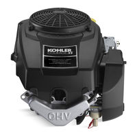
Kohler Courage SV600 Service Manual (113 pages)
Vertical crankshaft Courage Series
Brand:
Kohler
| Category:
Engine
| Size: 3.19 MB
Table of Contents
Table of Contents
2
Safety Precautions
3
Section 1. Safety and General Information
3
Explanation of Engine Identification Numbers
5
Oil Recommendations
6
Oil Type
6
Fuel Recommendations
6
Gasoline/Alcohol Blends
6
Storage
7
Maintenance Schedule
7
Periodic Maintenance
7
Safety and General Information
8
General Specifications
9
General Torque Values
15
Metric Fastener Torque Recommendations for Standard Applications
15
Oil Drain Plugs Tightening Torque: N-M (English Equiv.)
15
Torque Conversions
15
Flywheel Holding Tool
16
Section 2. Special Tools
16
Rocker Arm/Crankshaft Tool
17
Section 2 Special Tools
17
Section 3. Troubleshooting
18
External Engine Inspection
19
Cleaning the Engine
19
Basic Engine Tests
20
Crankcase Vacuum Test
20
Incorrect Vacuum in Crankcase
20
Leakdown Test Results
21
Cylinder Leakdown Test
21
Leakdown Test Instructions
21
Compression Test
21
Air Cleaner Assembly-Exploded View
22
Precleaner Service
22
Section 4. Air Cleaner and Air Intake System
22
Paper Element Service
23
Inspect Air Cleaner Components
23
Bushings in Air Cleaner Base
23
Disassembly
24
Breather Hose
24
Clean Air Intake/Cooling Areas
25
Fuel Type
26
Gasoline/Ether Blends
26
Section 5. Fuel System and Governor
26
Fuel Pump
27
Repair
27
Fuel Filter
27
Fuel System Troubleshooting Guide
27
Pulse Fuel Pump
28
Carburetor
28
Troubleshooting–Fuel System
28
Carburetor Adjustment
29
Fixed Main Jet Carburetor
29
Low Idle Mixture Adjustment
30
Optimum Low Idle Fuel Setting
30
Low Idle Speed Setting
30
Welch Plug Removal
31
Carburetor-Exploded View
31
Choke Shaft Removal
32
Throttle Shaft Removal
32
Cleaning
32
Main Fuel Jet Removal
32
Inspection
33
Choke Shaft Installation
33
Welch Plug Installation
33
Carburetor Reassembly
33
Throttle Cable Adjustment
34
Fuel Shut-Off Solenoid
34
Unitized Throttle and Choke Control
34
High Altitude Operation
34
Adjusting Unitized Throttle/Choke Control
35
Typical Throttle/Choke Controls
35
Starting an Engine Equipped with Unitized Throttle and Choke Control
35
Throttle Position for Starting Engine
35
Choke Adjustment
36
High Speed (RPM) Adjustment
36
Adjusting High Speed (RPM)
36
Choke Control Installation
37
Separate Throttle and Choke Control
37
Throttle Control Installation
37
Install Separate Control Cables
37
Changing the High Speed (RPM) on the Engines with Separate Controls (Increase or Decrease RPM)
38
Governed Idle Adjustment
38
Location of Governed Idle Adjusting Screw
38
Governor Gear/Flyweight Assembly
38
Operation
39
Initial Adjustment
39
Tightening Governor Lever Nut
39
Governor Sensitivity Adjustment
40
Governor Spring Location Chart
40
Viscosity Grades Table
41
Check Oil Level
41
Section 6. Lubrication System
41
Oil Drain Plug, Oil Filter
42
Oil Level Dipstick
42
Removing Dipstick
42
Change Oil and Oil Filter
42
Full-Pressure Lubrication System
43
Service
43
Oil Filter
43
Oil Sentry
43
Testing Oil Pressure
44
Testing the Oil Sentry Switch
44
Oil Sentry Pressure Switch Location
44
Installation
44
Spark Plug Service
45
Section 7. Electrical System and Components
45
Electronic CD Ignition System
47
Capacitive Discharge Ignition Module
48
Troubleshooting and Testing CD Ignition Systems
48
Preliminary Test
48
Testing CD Ignition Module Secondary
49
CD Ignition System Troubleshooting Guide
49
Ignition Tester, SPX Part No. KO1046
49
Battery Maintenance
50
Battery Test
50
Electrical Systems Wiring Diagrams and Battery Charging Systems
50
Battery Charging
50
3 Amp Unregulated Battery Charging System/70 Watt Lighting
51
Troubleshooting Guide 3 Amp Battery Charging System with 70 Watt Lighting Stator
52
Troubleshooting Guide 3 Amp/70 Watt Braking Stator
53
9 Or 15 Amp Regulated Battery Charging System
55
9 Or 15 Amp Stator and Rectifier-Regulator
56
Proper Connection to Test 9 or 15 Amp Charging System
56
Troubleshooting Guide 9 or 15 Amp Regulated Battery Charging System
57
Electric Starters
58
Troubleshooting Guide-Starting Difficulties
58
Drive Components
59
Assembling Inner Half of Tool Around the Armature Shaft and Retaining Ring
59
Starter Removal and Installation
59
Starter Drive Service
59
Retaining Ring Installation
60
Assembling Larger Inner Half Around Spring Retainer
60
Starter Disassembly
60
Inertia Drive Electric Starter
60
Commutator Service
61
Starter Reassembly
61
Removing Brush Carrier Assembly
61
Brush Replacement
61
Installing Brush Carrier Using Staples
62
Torquing Thru Bolts
62
Assembled Starter
62
Typical Disassembly Sequence
63
Drain Oil from Crankcase and Remove Oil Filter
63
Oil Drain Location, Oil Filter, and Oil Fill Cap/Dipstick
63
Section 8. Disassembly
63
Remove Electric Starter
64
Remove Muffler
64
Remove Blower Housing
64
Remove Oil Sentry Pressure Switch (on Models so Equipped)
64
Removing Electric Starter
65
Air Cleaner Components
65
Remove External Governor Components, Carburetor, and Fuel Pump
65
Remove Air Cleaner
65
Disconnecting Fuel Line from Carburetor
66
Disconnecting Pulse Line from Fitting
66
Removing Heat Deflector Screw and Ground Lead
66
Disconnecting Fuel Solenoid Lead
66
Removing Heat Deflector
67
Removing Speed Control Bracket from Closure Plate
67
Removing Governor Lever
67
Disconnecting Governor Spring
67
Remove Ignition Module
68
Removing Lead from Clip (RFI Suppression Equipped Units)
68
Remove Grass Screen, Fan, and Flywheel
68
Removing Fan and Flywheel Mounting Hardware
68
Valve Cover and Gasket Details
69
Remove Valve Cover and Cylinder Head
69
Removing Flywheel Using Puller
69
Remove the Stator
69
Removing Cylinder Head Bolts and Washer
70
Removing Cylinder Head and Gasket
70
Disassemble Cylinder Head
70
Removing Spark Plug
70
Remove Closure Plate
71
Closure Plate and Gasket Removed from Crankcase
71
Removing Valves with Spring Compressor
71
Disassembling Rocker Arm Components
71
Disassemble Closure Plate
72
Removing Governor Gear
72
Remove Cam Gears, Cam Shafts, and Oil Pump
72
Removing Exhaust Side Cam Shaft and Slotted Thrust Washer
73
Intake Cam Shaft and Oil Pump Assembly
73
Remove Connecting Rod and Piston
73
Removing Connecting Rod Cap
73
Balance Weight Disassembly
74
Remove Piston from Connecting Rod
74
Remove Crankshaft and Balance Weight Assembly
74
Remove Piston Rings
74
Removing Crank Gear Key
75
Removing Balance Weight Screw
75
Disassembled Balance Weight
75
Remove Governor Cross Shaft
75
Remove PTO and Flywheel Side Oil Seals
76
Automatic Compression Release (ACR)
77
ACR Details
77
Section 9. Inspection and Reconditioning
77
Cam Gears
78
Crankshaft and Crank Gear
78
Crankcase
78
Honing
78
Measuring Piston-To-Bore Clearance
79
Measuring Piston Diameter
79
Balance Weight Assembly
79
Measuring Balance Weight Guide Pin and Guide Shoe-To-Closure Plate Guide Channel Running Clearance
80
Balance Weight-To-Eccentric Clearance
80
Measuring Balance Weight to Crankshaft Eccentric Ring(S) Clearance
80
Measuring Guide Pin O.D.
81
Measuring Guide Shoe Hole I.D.
81
Flywheel
81
Cylinder Head and Valves
82
Valve Details
82
Valve Guides
85
Valve Seat Inserts
85
Lapping Valves
85
Pistons and Rings
85
Common Types of Piston and Ring Damage
86
Some Important Points to Remember When Servicing Piston Rings
87
Measuring Piston Ring End Gap
87
Measuring Piston Ring Side Clearance
87
Install Piston Rings
87
Procedure to Install Governor Shaft
88
Oil Pump Assembly and Pressure Relief Valve
88
Governor Gear and Shaft
88
Connecting Rods
88
Install PTO Side Oil Seal
90
Section 10. Reassembly
90
Install Governor Cross Shaft
91
Install Oil Pump Assembly and Intake Cam Shaft
91
Installing Oil Pump and Lower Drive Pin on Intake Cam Shaft
91
PTO Seal Depth Details
91
Assembled Intake Cam Shaft Details
92
Gerotor Gears Installed in Oil Pump
92
Installing Oil Pump Outlet Seal
92
Oil Pump Outlet Seals
92
Checking Outlet Seal Passage Opening (Open Style)
93
Install Crankshaft and Balance Weight
93
Installing Crank Gear Key
93
Torquing Oil Pump Mounting Screws
93
Assembled Piston and Connecting Rod
94
Install Piston and Connecting Rod
94
Install Piston to Connecting Rod
94
Installing Crankshaft Assembly
94
Direction Arrow on Piston
95
Install the Exhaust Cam Shaft and Cam Gear
95
Installing Cam Levers
95
Installing Piston and Connecting Rod
95
Exhaust Cam Shaft Installation
96
Hooking ACR Spring Onto Exhaust Cam Gear
96
Installing Exhaust Cam Gear
96
Spring Installed on ACR Weight
96
Install Closure Plate Gasket, Closure Plate, and Wiring Harness
97
Install Crank Gear
97
Install Flywheel Side Oil Seal
97
Install Intake Cam on Cam Shaft
97
Aligning and Installing Closure Plate
98
Assemble Cylinder Head
98
Closure Plate Installed
98
Install Cylinder Head
98
Install Rocker Arms and Push Rods
99
Installing Cylinder Head Fasteners
99
Installing Drain Back Check Ball
99
Installing Head Gasket
99
Adjusting Valve Clearance (Lash)
100
Install Valve Cover
100
Installing Push Rods and Rocker Arm Assemblies
100
Locking Adjustment Nut Set Screw
100
Connecting Pulse Line to Fitting
101
Install Pipe Plug or Fitting and Pulse Line for Fuel Pump
101
Install Stator and Wiring Harness
101
Installing B+Lead into Connector
101
Install Fan and Flywheel
102
Installing Fan and Mounting Hardware to Flywheel
102
Torquing Flywheel
102
Install Electric Starter
103
Install Ignition Module
103
Setting Air Gap
103
Tightening Clip Around Sheathing
103
Install Heat Deflector, Carburetor, Linkage and Air Cleaner Base
104
Install New Spark Plug
104
Installing Intake Gasket and Heat Deflector
104
Mounting Stud Installed
104
Connecting Fuel Line to Carburetor
105
Fuel Solenoid Lead Secured with Tie Strap
105
Installing Carburetor Assembly with Linkages
105
Securing Ground Lead
105
Install and Adjust Governor Lever
106
Installing Air Cleaner Base
106
Installing Mounting Screw
106
Torquing Air Cleaner Fasteners
106
Attaching Speed Control Bracket
107
Connecting Choke Linkage and Governor Spring
107
Install Fuel Pump (if Equipped)
107
Mounting Speed Control Bracket
107
Install Blower Housing and Flywheel Screen
108
Install Rectifier-Regulator
108
Installing Blower Housing Screws
108
Installing Fuel Pump
108
Install Air Cleaner Element, Precleaner, and Air Cleaner Cover
109
Install Oil Sentry or Pipe Plug
109
Installing Grass Screen
109
Installing Pipe Plug or Adapter
109
Install Muffler
110
Installing Air Cleaner Cover
110
Installing Precleaner
110
Install Drain Plug, Oil Filter, and Oil
110
Prepare the Engine for Operation
111
Testing the Engine
111
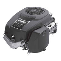
Kohler Courage SV600 Service Manual (119 pages)
VERTICAL CRANKSHAFT
Brand:
Kohler
| Category:
Engine
| Size: 4.91 MB
Table of Contents
Table of Contents
2
Safety Precautions
3
Section 1. Safety and General Information
3
Engine Identification Numbers
5
Oil Recommendations
6
Fuel Recommendations
6
Oil Type
6
Gasoline/Alcohol Blends
6
Periodic Maintenance
7
Storage
7
Typical Engine Dimensions
8
General Specifications
9
General Torque Values
15
Oil Drain Plugs Tightening Torque
15
Section 2. Tools & Aids
16
Special Tools You Can Make
19
Flywheel Holding Tool
19
Rocker Arm/Crankshaft Tool
19
Section 3. Troubleshooting
20
External Engine Inspection
21
Cleaning the Engine
21
Basic Engine Tests
22
Incorrect Vacuum in Crankcase
22
Compression Test
23
Cylinder Leakdown Test
23
Leakdown Test Instructions
23
Leakdown Test Results
23
Air Cleaner Assembly - Exploded View
24
Section 4. Air Cleaner and Air Intake System
24
Paper Element Service
25
Inspect Air Cleaner Components
25
Bushings in Air Cleaner Base
25
Air Intake/Cooling System
27
Section 5. Fuel System and Governor
28
Fuel Pump
29
Fuel Filter
29
Fuel System Troubleshooting Guide
29
Carburetor
30
Troubleshooting - Fuel System
30
Carburetor Adjustment
31
Low Idle Mixture Adjustment
32
Low Idle Speed Setting
32
Optimum Low Idle Fuel Setting
32
Welch Plug Removal
33
Carburetor - Exploded View
33
Cleaning
34
Main Fuel Jet Removal
34
Fuel Inlet Seat Removal
34
Choke Shaft Removal
34
Choke Shaft Installation
35
Welch Plug Installation
35
Carburetor Reassembly
35
Throttle Cable Adjustment
36
Fuel Shut-Off Solenoid
36
Unitized Throttle and Choke Control
36
High Altitude Operation
36
Adjusting Unitized Throttle/Choke Control
37
Typical Throttle/Choke Controls
37
Alignment Hole in Speed Control Bracket and Throttle Lever
37
Alignment Holes in Speed Control Bracket and Throttle Lever
37
High Speed (RPM) Adjustment
38
Throttle Position for Starting Engine
38
Separate Throttle and Choke Control
39
Choke Adjustment
39
Install Separate Control Cables
39
Choke Control Installation
40
Starting an Engine Equipped with Separate Control Cables
40
Governed Idle Adjustment
41
Changing the High Speed (RPM) on the Engines with Separate Controls
41
Setting the Low Idle RPM
41
Governor
41
Governor Operation
42
Governor Initial Adjustment
42
Governor Gear/Flyweight Assembly
42
Tightening Governor Lever Nut
42
Early Style Governor Spring Location Chart
43
Later Style Governor Spring Location Chart
43
Check Oil Level
44
Viscosity Grades Table
44
Section 6. Lubrication System
44
Change Oil and Oil Filter
45
Removing Dipstick
45
Dipstick Seated
45
Oil Level Dipstick
45
Oil Sentry
46
Oil Filter
46
Full-Pressure Lubrication System
46
Testing Oil Pressure
47
To Install the Oil Sentry Switch
47
Spark Plug Service
48
Section 7. Electrical System and Components
48
Spark Plug Inspection
49
Electronic CD Ignition System
50
Troubleshooting and Testing CD Ignition Systems
51
Capacitive Discharge Ignition Module
51
CD Ignition System Troubleshooting Guide
52
Ignition Tester
52
Testing CD Ignition Module Secondary
52
Battery Charging
53
Battery Maintenance
53
Battery Test
53
Electrical Systems Wiring Diagrams and Battery Charging Systems
53
3 Amp Regulated Battery Charging System/70 Watt Lighting
54
3 Amp/70 Watt Stator
54
Troubleshooting Guide 3 Amp Battery Charging System with 70 Watt Lighting Stator
55
Troubleshooting Guide 3 Amp/70 Watt Braking Stator
56
Battery Charging System 9 or 15 Amp
58
9 Or 15 Amp Stator and Rectifier-Regulator
59
Proper Connection to Test 9 or 15 Amp Charging System
59
Troubleshooting Guide 9 or 15 Amp Regulated Battery Charging System
60
Troubleshooting Guide - Starting Difficulties
61
Starting Motor Precautions
61
Electric Starters
61
Starter Removal and Installation
62
Retaining Ring Installation
63
Starter Disassembly
63
Brush Replacement
64
Commutator Service
64
Starter Reassembly
64
Assembled Starter
65
Installing Brush Carrier Using Staples
65
Torquing Thru Bolts
65
Typical Disassembly Sequence
66
Drain Oil from Crankcase and Remove Oil Filter
66
Oil Drain Location, Oil Filter, and Oil Fill Cap/Dipstick
66
Section 8. Disassembly
66
Remove Muffler
67
Remove Rectifier-Regulator
67
Remove Oil Sentry Pressure Switch
67
Remove Blower Housing
67
Remove Air Cleaner
68
Remove External Governor Components, Carburetor, and Fuel Pump
68
Removing Electric Starter
68
Removing Air Cleaner Cover
68
Disconnecting Fuel Solenoid Lead
69
Disconnecting Fuel Line from Carburetor
69
Removing Heat Deflector Screw and Ground Lead
69
Disconnecting Pulse Line from Fitting
69
Removing Speed Control Bracket from Closure Plate
70
Removing Heat Deflector
70
Disconnecting Governor Spring
70
Removing Governor Lever
70
Remove Grass Screen, Fan, and Flywheel
71
Removing Insert (some Models)
71
Removing Lead from Clip
71
Remove Ignition Module
71
Remove the Stator
72
Remove the Valve Cover and Cylinder Head
72
Removing Fan and Flywheel Mounting Hardware
72
Removing Flywheel Using Puller
72
Removing Drain Back Check Ball from Crankcase
73
Removing Cylinder Head and Gasket
73
Removing Cylinder Head Bolts and Washer
73
Loosening Adjustment Set Screw and Nut
73
Remove Closure Plate
74
Removing Spark Plug
74
Disassembling Rocker Arm Components
74
Disassemble Cylinder Head
74
Disassemble Closure Plate
75
Remove Cam Gears, Cam Shafts, and Oil Pump
75
Closure Plate and Gasket Removed from Crankcase
75
Removing Governor Gear
75
Removing Cam Levers
76
Removing Exhaust Side Cam Shaft and Slotted Thrust Washer
76
Removing Drain Back Tube
76
Outlet Seal Styles
76
Separating Oil Pump Assembly from Intake Side Cam Shaft
77
Removing Connecting Rod Cap
77
Intake Cam Shaft and Oil Pump Assembly
77
Remove Connecting Rod and Piston
77
Remove Crankshaft and Balance Weight Assembly
78
Remove Piston from Connecting Rod
78
Remove Piston Rings
78
Balance Weight Disassembly
79
Removing Crank Gear Key
79
Removing Balance Weight Screw and Guide Pin
79
Remove Governor Cross Shaft
80
Remove PTO and Flywheel Side Oil Seals
80
Disassembled Balance Weight
80
Removing Hitch Pin and Washer
80
Automatic Compression Release (ACR)
81
Section 9. Inspection and Reconditioning
81
Cam Gears
82
Crankshaft and Crank Gear
82
Crankcase
82
Clean Cylinder Bore after Honing
83
Balance Weight Assembly
83
Measuring Piston-To-Bore Clearance
83
Balance Weight-To-Eccentric Clearance
84
Measuring Balance Weight to Crankshaft Clearance
84
Measuring Balance Weight Guide Pin and Guide Shoe-To-Closure Plate Guide Channel Running Clearance
84
Flywheel Inspection
85
Measuring Guide Pin O.D.
85
Measuring Guide Shoe Hole I.D.
85
Cylinder Head and Valves Inspection and Service
86
Valve Guides
89
Valve Seat Inserts
89
Lapping Valves
89
Pistons and Rings
89
Common Types of Piston and Ring Damage
90
Install Piston Rings
91
Top and Middle Compression Ring End Gap
91
Closure Plate and Passage Cover
92
Connecting Rods
92
Oil Pump Assembly and Pressure Relief Valve
92
Governor Gear and Shaft
93
Governor Shaft Press Depth
93
Typical Reassembly Sequence
94
Install PTO Side Oil Seal
94
Section 10. Reassembly
94
Install Governor Cross Shaft
95
Install Oil Pump Assembly and Intake Cam Shaft
95
PTO Seal Depth Details
95
Assembled Intake Cam Shaft Details
96
Gerotor Gears Installed in Oil Pump
96
Pump Outlet Seals
96
Oil Pump Outlet Styles
96
Installing Drain Back Tube
97
Torquing Oil Pump Mounting Screws
97
Checking Outlet Seal Passage Opening
97
Install Crankshaft and Balance Weight
97
Assembling Balance Weight to Crankshaft
98
Installing Crank Gear Key
98
Installing Crankshaft Assembly
98
Install Piston and Connecting Rod
100
Direction Arrow on Piston
100
Install Cam Levers
101
Install the Exhaust Cam Shaft and Cam Gear
101
Drive Pin Locations for Exhaust Cam Shaft
101
Install Intake Cam on Cam Shaft
102
Install Crank Gear
102
Hooking ACR Spring Onto Exhaust Cam Gear
102
Install Flywheel Side Oil Seal
103
Install Closure Plate Gasket, Closure Plate, and Wiring Harness
103
Installing Drain Back Check Ball
104
Closure Plate Fastener Torque Sequence
104
Install Cylinder Head
104
Assemble Cylinder Head
104
Install Rocker Arms and Push Rods
105
Installing Cylinder Head Fasteners
105
Installing Guide Plates and Rocker Arm Pivot Studs
105
Install Valve Cover
106
Valve Clearance Specifications
106
Adjusting Valve Clearance
106
Locking Adjustment Nut Set Screw
106
Install Stator and Wiring Harness
107
Install Pipe Plug or Fitting and Pulse Line for Fuel Pump
107
Install Fan and Flywheel
108
Torquing Flywheel
108
Install Electric Starter
109
Install Ignition Module
109
Install Heat Deflector, Carburetor, Linkage and Air Cleaner Cleaner Base
110
Install New Spark Plug
110
Inserting Alignment Pin
111
Installing Carburetor Assembly with Linkages
111
Securing Ground Lead
111
Fuel Solenoid Lead Secured with Tie Strap
111
Install and Adjust Governor Lever
113
Mounting Speed Control Bracket
113
Install Fuel Pump
114
Install Rectifier-Regulator
114
Install Blower Housing and Flywheel Screen
114
Install Oil Sentry or Pipe Plug
115
Install Air Cleaner Element, Precleaner, and Air Cleaner Cover
116
Install Muffler
116
Install Drain Plug, Oil Filter, and Oil
117
Prepare the Engine for Operation
117
Testing the Engine
117
Advertisement
Kohler Courage SV600 Service Manual (76 pages)
Brand:
Kohler
| Category:
Engine
| Size: 2.73 MB
Kohler Courage SV600 Owner's Manual (48 pages)
Brand:
Kohler
| Category:
Engine
| Size: 4.13 MB
Table of Contents
Troubleshooting
8
Fehlersuche
16
Manual del Usuario
17
Manuel du Propriétaire
25
KOHLER Courage SV600 Owner's Manual (17 pages)
COURAGE SERIES VERTICAL CRANKSHAFT
Brand:
KOHLER
| Category:
Engine
| Size: 2.96 MB
Table of Contents
Safety Precautions
2
Oil/Fuel Recommendations
4
Oil Type
4
Typical Courage Series Vertical Shaft Engine
4
Engine Identification Numbers
5
Specifications
5
Operating Instruction S
6
Cold Weather Starting Hints
6
Pre-Start Checklist/Starting
6
Throttle Position for Starting Engine with Single-Lever Control
6
Stopping
7
Battery
7
Cooling
7
Engine Speed
7
Maintenance Instructions
8
Check Oil Level
8
Oil Sentry
9
Change Oil and Filter
9
Oil Level Dipstick
9
Service Precleaner and Air Cleaner Element
10
Service Paper Element
10
Air Cleaner Assembly
10
Removing Air Cleaner Element
10
Clean Air Intake/Cooling Areas
11
Ignition System
11
Check/Servicing Spark Plug
11
Battery Charging
11
Fuel Filter
12
Carburetor Troubleshooting and Adjustments
12
Troubleshooting
13
Optimum Low Idle Fuel Setting
13
Storage
13
Parts Ordering
14
Major Repair
14
Model Designation
14
Kohler Courage SV600 Owner's Manual (17 pages)
VERTICAL CRANKSHAFT
Brand:
Kohler
| Category:
Engine
| Size: 0.28 MB
Table of Contents
Safety Precautions
2
California Proposition 65 Warning
2
Oil Recommendations
4
Fuel Recommendations
4
Engine Identification Numbers
5
Specifications
6
Pre-Start Checklist
6
Cold Weather Starting Hints
6
Operating Instructions
6
Maintenance Instructions
8
Maintenance Schedule
8
Carburetor Troubleshooting and Adjustments
12
Troubleshooting
13
Engine Limited Warranty
14
Parts Ordering
14
Major Repair
14
Kohler Courage SV600 Owner's Manual (17 pages)
VERTICAL CRANKSHAFT
Brand:
Kohler
| Category:
Engine
| Size: 0.25 MB
Table of Contents
Safety Precautions
2
California Proposition 65 Warning
2
Oil Recommendations
4
Fuel Recommendations
4
General Recommendations
4
Engine Identification Numbers
5
Specifications
6
Pre-Start Checklist
6
Cold Weather Starting Hints
6
Maintenance Instructions
8
Maintenance Schedule
8
Carburetor Troubleshooting and Adjustments
12
Troubleshooting
13
Engine Limited Warranty
14
Advertisement
Related Products
Kohler Courage SV620
Kohler Courage SV610
Kohler COURAGE SV600S
Kohler Courage SV601
Kohler COURAGE SV710-740
Kohler SV470-620
Kohler Courage SV715
Kohler Courage SV730
Kohler SV810
Kohler SV2250
KOHLER Categories
Plumbing Product
Bathroom Fixtures
Bathtubs
Toilets
Engine
More KOHLER Manuals
Login
Sign In
OR
Sign in with Facebook
Sign in with Google
Upload manual
Upload from disk
Upload from URL