User Manuals: Kohler Command CV740 Vertical Engine
Manuals and User Guides for Kohler Command CV740 Vertical Engine. We have 7 Kohler Command CV740 Vertical Engine manuals available for free PDF download: Service Manual, Owner's Manual
Advertisement


Advertisement

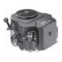
Kohler Command CV740 Owner's Manual (20 pages)
Command series
Vertical Crankshaft
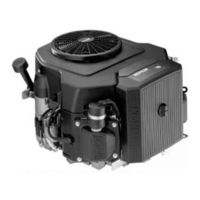
Kohler Command CV740 Owner's Manual (20 pages)
Vertical Crankshaft

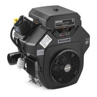
Kohler Command CV740 Owner's Manual (8 pages)
vertical/horizontal crankshaft
Brand: Kohler
|
Category: Crankshaft
|
Size: 1.14 MB
Advertisement