Sign In
Upload
Manuals
Brands
Kintech Engineering Manuals
Data Loggers
ORBIT 360
Kintech Engineering ORBIT 360 Manuals
Manuals and User Guides for Kintech Engineering ORBIT 360. We have
1
Kintech Engineering ORBIT 360 manual available for free PDF download: User Manual
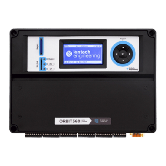
Kintech Engineering ORBIT 360 User Manual (139 pages)
Brand:
Kintech Engineering
| Category:
Data Loggers
| Size: 5.32 MB
Table of Contents
Index
3
Table of Contents
3
List of Figures
10
List of Acronyms
15
1 General User Information
16
Contact Information
16
Warranty and Liability
17
About this User Manual
18
Product Disposal
18
Getting Help
18
2 Introduction
20
About Orbit 360
21
Orbit 360 Basic Plus
22
Orbit 360 Premium
22
Order Options and Accessories
22
Fig. 1. Included Items Along with the Orbit 360 Data Logger
23
Data Loggers
24
Kintech SIM Cards
24
Fig. 2. Global Internet SIM Card
25
3 Quick Start
26
How to Get an Atlas License / Atlas Software
26
System Requirements
26
How to Setup Your Orbit Data Logger
26
Main Dashboard
27
General Settings
27
Channels Settings
27
Communication Settings
27
Scheduled Download Settings
27
Upload Settings
28
SD Memory Card Inserted into the PC
28
SD Card Inserted into the Data Logger
28
How to Operate Orbit Data Logger in Field
29
How to Download Data from an Orbit Data Logger
30
4 System Overview
31
Orbit 360 Data Logger
31
General Aspects
31
Fig. 3. Where to Find Orbit 360 Serial Number
31
Sampling Rate
32
Averaging Period and Timestamp
32
Basics about Data Management for Kintech Loggers
32
Configuration Changes Becoming Effective
33
Logger Reset
33
Fig. 4. Understanding the Data Management System
33
Internal Tilt Sensor
34
Component Map
34
Fig. 5. Orbit 360 Component Map
34
Display
35
Keypad
35
LED Indicators
35
CPU (Green LED)
35
Modem (Red LED)
35
External Battery
36
GPS (Blue LED)
36
Fig. 6. External Battery Connector
36
Grounding Terminal
37
Modem
37
Gps
37
Fig. 7. GPS and GSM Antenna Connectors
37
Rtc
38
TCP Connector
38
MMC Card Slot
38
Fig. 8. Ethernet Port of the Orbit 360 Data Logger
38
SIM Card Slot
39
Logger Terminals
39
Fig. 9. Orbit 360 Removable Terminals
39
Table 1. Orbit 360 Terminals Grouping
40
Fig. 10. Orbit 360 Terminal Map Drawing
41
Alarms and Actuators
46
Table 2. Orbit 360 Terminal Description
46
Atlas Desktop Software
47
Atlas Free
47
Atlas Professional
47
Atlas Enterprise
48
5 Technical Specifications
48
Operation Conditions
48
Absolute Maximum Ratings
48
Table 3. Electrical Specifications: Inputs
49
Table 4. Operating Temperature Range
49
Technical Specifications: Outputs
50
Technical Specifications: Input Channels
52
Frequency / Counters Channels
52
Analog Channels
55
Communication / Protocols
57
Data Collection and Storage
59
Other Specifications
60
Emergency Power Saving Mode
60
Internal Backup Batteries
60
Physical Characteristics
61
6 Installation
62
Fig. 11. Adjusting the Logger Hanging Brackets
62
Fig. 12. Hanging Brackets Dimensions (Horizontal Position)
63
Fig. 13. Hanging Brackets Dimensions (Vertical Position)
63
Preparation
64
Configuration
64
Grounding
64
Antennas
66
Fig. 14. How to Ground the Logger
66
Sensor Connection
67
Fig. 15. GSM Antenna
67
Fig. 16. GPS Antenna
67
Fig. 17. Antenna Connectors in Orbit 360
67
Powering on the Logger
68
7 On-Site Operations
69
Using the Keypad
69
Fig. 18. Orbit 360 Keypad
69
Turning off the Logger
70
Table 5. Keypad Key Functions
70
Using the Display
71
Upper Information Bar
71
Fig. 19. Orbit 360 Display
71
Fig. 20. Memory Being Accessed Icon
72
Table 6. Display: Battery Status
72
Lower Information Bar
73
Fig. 21. Logger Site ID Number
73
Table 7. Display: Communication Status
73
Fig. 22. Logger Data and Time
74
Fig. 23. GPS Status
74
Fig. 24. RS485 Communication Status Indicator
74
Fig. 25. Modbus Status Indicator
74
Parameter Edit Mode
75
Fig. 26. Edit Mode (Sensor Model)
75
Navigation Menus on Logger Display
76
Fig. 27. Orbit 360 Main Menu View (1)
76
Fig. 28. Orbit 360 Main Menu View (2)
76
Quick View
77
Frequency 1-16
77
Fig. 29. Orbit 360 Main Menu View (3)
77
Fig. 30. QUICK VIEW Screen
77
Analog 1-8
78
Analog 9-23
78
Fig. 31. FREQUENCY 1-10 Screen
78
Fig. 32. ANALOG 1-8 Screen
78
Status
79
Logger Status
79
Fig. 33. STATUS Screen: Logger Status
80
Table 8. Logger Status: Error Code Number
81
Modem
82
Fig. 34. STATUS Screen: Modem
82
Serial Channels
83
Modbus
84
Fig. 35. STATUS Screen: Serial Channels
84
Fig. 36. STATUS Screen: Modbus
84
GPS Location
85
Fig. 37. STATUS Screen: Site Coordinates
85
Power Supply
86
Fig. 38. STATUS Screen: Power Supply
86
System Info
87
Fig. 39. STATUS Screen: System Info
87
Configuration
88
Fig. 40. Configuration Menu
88
Modem Type
89
Table 9. Configuration: Modem Types
89
Modbus RTU
90
Fig. 41. Configuration: Modem Types
90
Area Number
91
Fig. 42. Configuration: Modbus RTU
91
Fig. 43. Configuration: Area Number
91
Table 10. Configuration: Modbus RTU
91
Location Number
92
Num 1 2
92
Tower Number
92
Fig. 44. Configuration: Location Number
92
Fig. 45. Configuration: Tower Number
92
Num 3 4
93
Fig. 46. Configuration: Num 1 2
93
Fig. 47. Configuration: Num 3 4
93
Language
94
Flags Configuration
94
Mode
94
Fig. 48. Configuration: Language
94
Sensor Model
95
Fig. 49. Sensor Model
95
Time & Date
100
On-Site Logger Configuration Via SD Card
101
Fig. 50. Time & Date Configuration Screen
101
Changing the SIM Card (PIN Code)
102
Fig. 51. Uploading Settings to a SD Memory Card Connected to Your PC
102
Sensor Replacement
103
Downloading from SD Card
104
Fig. 52. How to Take out the SD Card
104
Fig. 53. Display: Checking Memory Card
105
Fig. 54. Display: Storage Cycle Instructions
105
Fig. 55. Display: New Storage Cycle Screen
105
8 Data Security
106
Fig. 56. Display: Old Storage Cycle Continues
106
Orbit Passwords
107
Atlas Passwords
107
9 Communication Options
108
Gsm/Gprs
108
Internet
108
Logger Server Name (LNS)
109
Fig. 57. Logger Server Name
109
Kintech Global Internet SIM Cards
110
Modem Call (CSD)
111
Fig. 58. Kintech Global SIM Card
111
Sms
112
Email
113
Satellite
115
Iridium
116
Characteristics
117
Fig. 59. Iridium Modem
117
Installation (Logger Side)
118
Fig. 60. Satellite: Iridium
118
Fig. 61. Iridium Antenna for Satellite Connection
119
Fig. 62. Iridium Satellite Connection Diagram (Logger Side)
119
Installation (Office Side)
120
Bgan
120
Fig. 63. Iridium Satellite Connection Diagram (Office Side)
120
Characteristics
121
Fig. 64. BGAN Satellite Modem (Logger Side)
121
Installation (Logger Side)
122
Fig. 65. Satellite: BGAN
122
Fig. 66. Direct COM Terminals: 44 and 43
122
Installation (Office Side)
123
Direct COM
123
Fig. 67. Iridium Satellite Connection Diagram (Logger Side)
123
Fig. 68. Direct COM Terminals: 44 and 43
123
Troubleshooting
124
Internet Troubleshooting
124
Fig. 69. Logger Display: Logger Showing "GSM
125
Fig. 70. Logger Display: Status > Modem > E04 (Logger Online)
125
Fig. 71. Modem Status Codes List
126
Satellite Troubleshooting
127
10 Scada
128
Modbus Configuration
128
Fig. 72. Selection of Modbus Variables to be Transmitted
129
Fig. 73. Example of Modbus Variables Addresses
130
Fig. 74. Several Loggers Using a Shared Communication Line
131
Table 11. Modbus RTU Types and Baudrates3941
131
Table 12. Typical Modbus Configuration
133
Modbus RTU Troubleshooting
134
Fig. 75. Modscan Configuration (Office Test for Mobdus RTU)
134
Modbus Types
135
Modbus TCP
137
Fig. 76. Example Configuration for Modbus TCP
137
11 EC Declaration of Conformity
139
Advertisement
Advertisement
Related Products
Kintech Engineering Categories
Measuring Instruments
Data Loggers
Control Unit
Tablet
More Kintech Engineering Manuals
Login
Sign In
OR
Sign in with Facebook
Sign in with Google
Upload manual
Upload from disk
Upload from URL