Sign In
Upload
Manuals
Brands
Keysight Technologies Manuals
Measuring Instruments
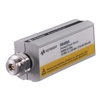
N8487A
Keysight Technologies N8487A Manuals
Manuals and User Guides for Keysight Technologies N8487A. We have
1
Keysight Technologies N8487A manual available for free PDF download: Operating And Service Manual
Keysight Technologies N8487A Operating And Service Manual (80 pages)
Power Sensors
Brand:
Keysight Technologies
| Category:
Measuring Instruments
| Size: 1.2 MB
Table of Contents
Safety Symbols
5
Regulatory Markings
6
General Safety Information
7
Waste Electrical and Electronic Equipment (WEEE) Directive 2002/96/EC
8
Environmental Conditions
9
In this Guide
11
Table of Contents
13
1 Introduction
19
General Information
20
Figure 1-1 N8480 Series Power Sensors
20
Accessories Shipped with the Instrument
21
Initial Inspections
21
Original Packaging
21
Power Meter and Sensor Cable Requirements
22
Table 1-1 Power Sensor Cable Options
22
Figure 1-2 Connecting a Sensor Cable to Power Meter
23
Interconnection and Calibration
23
Recommended Calibration Interval
24
Temperature Sensitivity
24
Figure 1-3 Connecting Waveguide Flange to the N8486AQ Power Sensor
25
Operating Instructions
25
Modulation Effect
26
Table 1-2 RF Connector Type, Wrench Size, and Torque Values
26
Torque
26
Overview of the N8480 Series Power Sensors
27
Table 1-3 Power Range in Range Setting
28
Figure 1-4 N8480 Series Power Sensor Simplified Block Diagram
29
Figure 1-5 N8485A Power Sensor with Adapter
30
Figure 1-6 N8487A Power Sensor with Adapter
30
N8485A Power Sensor
30
N8487A Power Sensor
30
B-Models and H-Models Information
31
Figure 1-7 N8488A Power Sensor with Adapter
31
N8488A Power Sensor
31
Waveguide-Models Information
32
Options
33
Power Meter Firmware Compatibility
34
Table 1-4 Power Meter Firmware
34
Power Meter Configuration Changes
35
Figure 1-8 Auto-Averaging Settings
35
Measurement Accuracy and Speed
36
Measurement Considerations
36
2 Specifications and Characteristics
37
Specification Definitions
38
Warranted Specifications
38
Characteristic Specifications
38
Conditions
39
Specifications
40
Frequency and Dynamic Power Range
40
Table 2-1 Frequency and Dynamic Power Range
40
Damage Level
41
Table 2-2 Damage Level at Average and Peak Power
41
Maximum SWR
42
Table 2-3 Maximum SWR
42
Figure 2-1 Typical SWR, 10 Mhz to 18 Ghz (25 °C ±10 °C) for N8481A Power Sensor
43
Figure 2-2 Typical SWR, 100 Khz to 6 Ghz (25 °C ±10 °C) for N8482A Power Sensor
44
Figure 2-3 Typical SWR, 10 Mhz to 26.5 Ghz (25 °C ±10 °C) for N8485A Power Sensor
44
Figure 2-4 Typical SWR, 50 Mhz to 50 Ghz (25 °C ±10 °C) for N8487A Power Sensor
45
Figure 2-5 Typical SWR, 10 Mhz to 70 Ghz (25 °C ±10 °C) for N8488A Power Sensor
45
Figure 2-6 Typical SWR, 33 Mhz to 50 Ghz (25 °C ±10 °C) for N8486AQ Power Sensor
46
Figure 2-7 Typical SWR, 26.5 Ghz to 40 Ghz (25 °C ±10 °C) for N8486AR Power Sensor
46
Figure 2-8 Typical SWR, 10 Mhz to 18 Ghz (25 °C ±10 °C) for N8481B Power Sensor
47
Figure 2-9 Typical SWR, 100 Khz to 6 Ghz (25 °C ±10 °C) for N8482B Power Sensor
47
Figure 2-10 Typical SWR, 10 Mhz to 18 Ghz (25 °C ±10 °C) for N8481H Power Sensor
48
Figure 2-11 Typical SWR, 100 Khz to 6 Ghz (25 °C ±10 °C) for N8482H Power Sensor
48
Power Linearity
49
Table 2-4 Power Linearity
49
Figure 2-12 Typical N8481/2/5/7/8A and N8486AR/AQ Power Linearity at 25 °C, after Zero and Calibration with Associated Measurement Uncertainty
50
Figure 2-13 Typical N8481/2B Power Linearity at 25 °C, after Zero and Calibration with
51
Figure 2-14 Typical N8481/2H Power Linearity at 25 °C, after Zero and Calibration with
52
Switching Point
53
Table 2-5 Switching Point Hysteresis
53
Zero Set, Zero Drift and Measurement Noise
54
Table 2-6 Zero Set, Zero Drift and Measurement Noise
54
Settling Time
55
Figure 2-15 Autofilter, Default Resolution, 10 Db Decreasing Power Step (Not Across the Switching Point)
55
Table 2-7 Settling Time in Normal and X2 Mode
55
Calibration Factor and Reflection Coefficient
56
Calibration Factor Uncertainty
57
Table 2-8 Calibration Factor Uncertainty at 25 ºC ± 3 ºC
57
Table 2-9 Calibration Factor Uncertainty at 25 ºC ± 10 ºC
58
Table 2-10 Calibration Factor Uncertainty at 0 ºC to 55 ºC
60
Supplemental Characteristics
61
Figure 2-16 Typical Cal Factor and SWR Vs. Frequency
61
Physical Characteristics
62
Table 2-11 Physical Dimensions
62
3 Service
63
Cleaning
64
Connector Care
64
Principle of Operations
65
Performance Test
66
Standing Wave Ratio (SWR) and Reflection Coefficient (Rho) Performance Test
66
Table 3-1 Reflection Coefficient for N8480 Series Power Sensors (25 ºC ± 10 ºC)
67
Zero Set Performance Test
69
Replaceable Parts
71
Figure 3-1 Illustrated Parts Breakdown
72
Table 3-2 Replaceable Parts List for Standard N8480 Series Power Sensors
73
Table 3-3 Replaceable Parts List for N8480 Series Power Sensors with Option CFT
75
Table 3-4 Replacement Part List for Adapters Used on N8480 Series Power Sensors
76
Troubleshooting
77
Repair
77
Diassembly/Reassembly Procedures
78
Diassembly Procedure
78
Reassembly Procedure
78
Figure 3-2 Removing Power Sensor Shell
78
Advertisement
Advertisement
Related Products
Keysight Technologies N8480 Series
Keysight Technologies N8481A
Keysight Technologies N8482A
Keysight Technologies N8481B
Keysight Technologies N8482B
Keysight Technologies N8481H
Keysight Technologies N8482H
Keysight Technologies N8485A
Keysight Technologies N8486AQ
Keysight Technologies N8486AR
Keysight Technologies Categories
Measuring Instruments
Test Equipment
Control Unit
Portable Generator
Power Supply
More Keysight Technologies Manuals
Login
Sign In
OR
Sign in with Facebook
Sign in with Google
Upload manual
Upload from disk
Upload from URL