Sign In
Upload
Manuals
Brands
Keysight Technologies Manuals
Test Equipment
DSO-X 2024A
Keysight Technologies DSO-X 2024A Manuals
Manuals and User Guides for Keysight Technologies DSO-X 2024A. We have
1
Keysight Technologies DSO-X 2024A manual available for free PDF download: User Manual
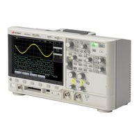
Keysight Technologies DSO-X 2024A User Manual (352 pages)
InfiniiVision 2000 X-Series
Brand:
Keysight Technologies
| Category:
Test Equipment
| Size: 6.52 MB
Table of Contents
Safety Notices
2
Infiniivision 2000 X-Series Oscilloscopes-At a Glance
4
In this Guide
6
Table of Contents
9
1 Getting Started
23
Inspect the Package Contents
23
Learn the Front Panel Controls and
23
Install the Optional LAN/VGA or GPIB Module
26
Tilt the Oscilloscope for Easy Viewing
26
Power-On the Oscilloscope
27
Connect Probes to the Oscilloscope
28
Maximum Input Voltage at Analog Inputs
28
Do Not Float the Oscilloscope Chassis
29
Input a Waveform
29
Recall the Default Oscilloscope Setup
29
Use Auto Scale
30
Compensate Passive Probes
32
Learn the Front Panel Controls and Connectors
33
Front Panel Overlays for Different Languages
41
Learn the Rear Panel Connectors
43
Learn the Oscilloscope Display
45
Access the Built-In Quick Help
47
2 Horizontal Controls
49
To Adjust the Horizontal (Time/DIV) Scale
50
To Adjust the Horizontal Delay (Position)
51
Panning and Zooming Single or Stopped Acquisitions
52
To Change the Horizontal Time Mode (Normal, XY, or Roll)
52
XY Time Mode
53
To Display the Zoomed Time Base
56
To Change the Horizontal Scale Knob's Coarse/Fine Adjustment Setting
57
To Position the Time Reference (Left, Center, Right)
58
Searching for Events
58
To Set up Searches
59
Navigating the Time Base
59
To Navigate Time
59
To Navigate Search Events
60
To Navigate Segments
60
3 Vertical Controls
64
To Turn Waveforms on or off (Channel or Math)
64
To Adjust the Vertical Scale
65
To Adjust the Vertical Position
65
To Specify Channel Coupling
65
To Specify Bandwidth Limiting
66
To Change the Vertical Scale Knob's Coarse/Fine Adjustment Setting
66
To Invert a Waveform
67
Setting Analog Channel Probe Options
67
To Specify the Channel Units
68
To Specify the Probe Attenuation
68
To Specify the Probe Skew
69
4 Math Waveforms
71
To Display Math Waveforms
71
To Perform a Transform Function on an Arithmetic Operation
72
See also "To Perform a Transform Function on an Arithmetic Operation
72
To Adjust the Math Waveform Scale and Offset
73
Units for Math Waveforms
73
Math Operators
74
Add or Subtract
74
Multiply or Divide
75
Math Transforms
76
FFT Measurement
76
FFT Measurement Hints
80
FFT Units
81
FFT DC Value
81
FFT Aliasing
81
FFT Spectral Leakage
83
5 Reference Waveforms
85
To Save a Waveform to a Reference Waveform Location
85
To Display a Reference Waveform
86
To Scale and Position Reference Waveforms
87
To Adjust Reference Waveform Skew
87
To Display Reference Waveform Information
88
To Save/Recall Reference Waveform Files To/From a USB Storage Device
88
To Connect the Digital Probes to the Device under Test
89
6 Digital Channels
90
Probe Cable for Digital Channels
90
Acquiring Waveforms Using the Digital Channels
93
To Display Digital Channels Using Autoscale
93
Interpreting the Digital Waveform Display
94
To Change the Displayed Size of the Digital Channels
95
To Switch a Single Channel on or off
96
To Switch All Digital Channels on or off
96
To Switch Groups of Channels on or off
96
To Change the Logic Threshold for Digital Channels
96
To Reposition a Digital Channel
97
To Display Digital Channels as a Bus
98
Digital Channel Signal Fidelity: Probe Impedance and Grounding
101
Input Impedance
101
Probe Grounding
103
Best Probing Practices
105
7 Serial Decode
107
Serial Decode Options
107
Lister
108
Searching Lister Data
110
Searching for UART/RS232 Data in the
111
8 Display Settings
113
To Adjust Waveform Intensity
113
To Set or Clear Persistence
115
To Clear the Display
116
To Select the Grid Type
116
To Adjust the Grid Intensity
117
To Freeze the Display
117
9 Labels
119
To Turn the Label Display on or off
119
To Assign a Predefined Label to a Channel
120
To Define a New Label
121
To Load a List of Labels from a Text File You Create
122
To Reset the Label Library to the Factory Default
123
10 Triggers
125
Adjusting the Trigger Level
126
Edge Trigger
127
Forcing a Trigger
127
Pattern Trigger
130
Hex Bus Pattern Trigger
132
Pulse Width Trigger
132
Video Trigger
135
To Trigger on a Specific Line of Video
138
To Trigger on All Sync Pulses
140
To Trigger on a Specific Field of the Video Signal
140
To Trigger on All Fields of the Video Signal
141
To Trigger on Odd or Even Fields
142
Serial Trigger
144
11 Trigger Mode/Coupling
147
To Select the Auto or Normal Trigger Mode
148
To Select the Trigger Coupling
149
To Enable or Disable Trigger HF Reject
151
To Enable or Disable Trigger Noise Rejection
151
External Trigger Input
152
Maximum Voltage at Oscilloscope External Trigger Input
153
To Set the Trigger Holdoff
152
12 Acquisition Control
155
Running, Stopping, and Making Single Acquisitions (Run Control)
155
Overview of Sampling
156
Sampling Theory
157
Aliasing
157
Oscilloscope Bandwidth and Sample Rate
157
Oscilloscope Rise Time
159
Oscilloscope Bandwidth Required
160
Memory Depth and Sample Rate
160
Selecting the Acquisition Mode
161
Normal Acquisition Mode
162
Peak Detect Acquisition Mode
162
Averaging Acquisition Mode
164
High Resolution Acquisition Mode
166
Acquiring to Segmented Memory
167
Navigating Segments
168
Infinite Persistence with Segmented Memory
169
Segmented Memory Re-Arm Time
169
Saving Data from Segmented Memory
169
To Make Cursor Measurements
172
Cursor Examples
175
To Make Automatic Measurements
182
Measurements Summary
184
Snapshot All
185
Voltage Measurements
186
Peak-Peak
186
Maximum
187
Minimum
187
Amplitude
187
Top
187
Base
188
Overshoot
188
Preshoot
189
Average
190
DC Rms
190
Ac Rms
191
Time Measurements
193
Period
193
Frequency
194
Width
195
Duty Cycle
195
Rise Time
195
Fall Time
195
Delay
196
Phase
197
Measurement Thresholds
198
Measurement Window with Zoom Display
200
15 Mask Testing
201
To Create a Mask from a "Golden" Waveform (Automask)
201
Mask Test Setup Options
203
Mask Statistics
206
To Manually Modify a Mask File
207
Building a Mask File
210
How Is Mask Testing Done
212
16 Digital Voltmeter
213
To Select Generated Waveform Types and Settings
217
To Output the Waveform Generator Sync Pulse
220
To Specify the Expected Output Load
220
17 Waveform Generator
220
To Use Waveform Generator Logic Presets
221
To Add Modulation to the Waveform Generator Output
222
To Set up Amplitude Modulation (AM)
223
To Set up Frequency Modulation (FM)
224
To Set up Frequency-Shift Keying Modulation (FSK)
226
To Add Noise to the Waveform Generator Output
222
To Restore Waveform Generator Defaults
227
18 Save/Recall (Setups, Screens, Data)
229
Saving Setups, Screen Images, or Data
229
To Save Setup Files
231
To Save BMP or PNG Image Files
231
To Save CSV, ASCII XY, or bin Data Files
232
Length Control
233
To Save Lister Data Files
234
To Save Reference Waveform Files to a USB Storage Device
235
To Save Masks
235
To Navigate Storage Locations
236
To Enter File Names
236
Recalling Setups, Masks, or Reference Waveforms
237
To Recall Setup Files
237
To Recall Mask Files
238
To Recall Reference Waveform Files from a USB Storage Device
238
Recalling Default Setups
238
Performing a Secure Erase
239
19 Print (Screens)
241
To Print the Oscilloscope's Display
241
To Set up Network Printer Connections
242
To Specify the Palette Option
244
To Specify the Print Options
244
I/O Interface Settings
247
Setting up the Oscilloscope's LAN Connection
248
To Establish a LAN Connection
249
Stand-Alone (Point-To-Point) Connection to a PC
250
20 Utility Settings
248
File Explorer
251
Setting Oscilloscope Preferences
253
To Choose "Expand About" Center or Ground
253
To Disable/Enable Transparent Backgrounds
254
To Load the Default Label Library
254
To Set up the Screen Saver
254
To Set Autoscale Preferences
255
Setting the Oscilloscope's Clock
256
Setting the Rear Panel TRIG out Source
256
Performing Service Tasks
257
To Perform User Calibration
257
To Perform Hardware Self Test
260
To Perform Front Panel Self Test
261
To Display Oscilloscope Information
261
To Display the User Calibration Status
261
To Clean the Oscilloscope
261
To Check Warranty and Extended Services Status
261
To Contact Keysight
262
To Return the Instrument
262
Configuring the [Quick Action] Key
262
Adding an Annotation
263
21 Web Interface
267
Accessing the Web Interface
268
Browser Web Control
269
Real Scope Remote Front Panel
270
Simple Remote Front Panel
271
Browser-Based Remote Front Panel
272
Remote Programming Via the Web Interface
273
Remote Programming with Keysight IO Libraries
274
Save/Recall
275
Saving Files Via the Web Interface
275
Recalling Files Via the Web Interface
276
Get Image
277
Identification Function
278
Instrument Utilities
278
Setting a Password
280
22 Reference
283
Measurement Category
283
Oscilloscope Measurement Category
283
Measurement Category Definitions
284
Maximum Input Voltages
284
Maximum Input Voltage at Analog Inputs
284
Maximum Input Voltage at Digital Channels
285
Specifications and Characteristics
283
Environmental Conditions
285
Probes and Accessories
285
Loading Licenses and Displaying License Information
286
Licensed Options Available
286
Other Options Available
287
Upgrading to an MSO
287
Binary Data (.Bin) Format
288
Binary Data in MATLAB
289
Binary Header Format
289
Example Program for Reading Binary Data
292
Examples of Binary Files
292
Software and Firmware Updates
288
CSV and ASCII XY Files
295
CSV and ASCII XY File Structure
296
Minimum and Maximum Values in CSV Files
296
Acknowledgements
297
Product Markings and Regulatory Information
299
23 CAN/LIN Triggering and Serial Decode
301
Setup for CAN Signals
301
CAN Triggering
303
CAN Serial Decode
305
Interpreting CAN Decode
306
CAN Totalizer
307
Interpreting CAN Lister Data
308
Searching for CAN Data in the Lister
309
Setup for LIN Signals
309
LIN Triggering
311
LIN Serial Decode
312
Interpreting LIN Decode
314
Interpreting LIN Lister Data
315
Searching for LIN Data in the Lister
316
24 I2C/SPI Triggering and Serial Decode
317
Setup for I2C Signals
317
I2C Triggering
318
I2C Serial Decode
322
Interpreting I2C Decode
323
Interpreting I2C Lister Data
324
Searching for I2C Data in the Lister
324
Setup for SPI Signals
325
SPI Triggering
329
SPI Serial Decode
331
Interpreting SPI Decode
332
Interpreting SPI Lister Data
333
Searching for SPI Data in the Lister
333
Setup for UART/RS232 Signals
335
25 UART/RS232 Triggering and Serial Decode
335
UART/RS232 Triggering
337
UART/RS232 Serial Decode
339
Interpreting UART/RS232 Lister
340
Uart/Rs232
341
Advertisement
Advertisement
Related Products
Keysight Technologies DSO-X 2002A
Keysight Technologies DSO-X 2012A
Keysight Technologies DSO-X 2022A
Keysight Technologies DSO-X 2004A
Keysight Technologies DSOX1102A
Keysight Technologies DSOX1102G with DSX1B7T12
Keysight Technologies InfiniiVision DSOX1204A
Keysight Technologies InfiniiVision DSOX1204G
Keysight Technologies DSOZ254A
Keysight Technologies DSO1004A
Keysight Technologies Categories
Measuring Instruments
Test Equipment
Control Unit
Portable Generator
Power Supply
More Keysight Technologies Manuals
Login
Sign In
OR
Sign in with Facebook
Sign in with Google
Upload manual
Upload from disk
Upload from URL