Sign In
Upload
Manuals
Brands
Keysight Manuals
Measuring Instruments
N9917A
Keysight N9917A Manuals
Manuals and User Guides for Keysight N9917A. We have
3
Keysight N9917A manuals available for free PDF download: User Manual
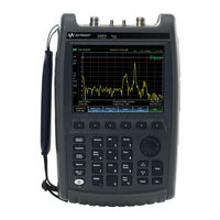
Keysight N9917A User Manual (870 pages)
Brand:
Keysight
| Category:
Measuring Instruments
| Size: 30.59 MB
Table of Contents
Table of Contents
7
Models and Options
35
Overview
35
Accessories
36
Optional Accessories
36
Conventions that Are Used in the Manual
37
Fieldfox Manuals, Software, and Supplemental Help
37
Safety Notes
38
Check the Shipment
39
Meeting Power Requirements for the AC/DC Adapter
39
Preparing for Initial Use of Your New Fieldfox
39
Battery Charge Status Is Viewable
40
Battery Usage
40
Install the Lithium-Ion Battery
40
Fieldfox ON/OFF Settings
41
To Conserve Battery Power
41
To Recharge a Battery
41
Fieldfox High Temperature Protection
42
How to Monitor the Internal Fieldfox Temperature
42
Power Button LED Status
42
Entering Temperature Control Mode
43
Temperature Control Mode
43
Exiting Maximum Auto Protect Threshold Temperature Mode
44
High-Temp Shutdown Warning (RTSA Mode Only)
45
Avoid Overpowering the Fieldfox
46
Summary of Fieldfox Average Internal Temperature Protection Behavior
46
Front Panel
48
Take the Fieldfox Tour
48
Top Panel
51
Right Side Panel
52
Left Side Panel
53
Screen Tour
54
How to Enter Numeric Values
56
Multiplier Abbreviations
56
Connector Care
57
CAT (Cable and Antenna Test) Mode
59
CAT Mode Settings
61
How to Select a CAT Mode Measurement
61
How to Select CAT Mode
61
Measurement Selection
61
How to View and Change Quick Settings
62
Quick Settings Table
62
Frequency Range
63
How to Set Frequency Range
63
How to Set Scale
63
Scale Settings
63
Averaging
64
How to Set Single or Continuous
65
How to Set Trace Averaging
65
Single or Continuous Measure
65
Smoothing
65
How to Set Resolution
66
Resolution (Number of Data Points)
66
Sweep Time
66
How to Set Output Power
67
How to Set Sweep Time
67
Output Power
67
Coupled Frequency
68
How to Set Coupled Frequency
68
How to Set Interference Rejection
68
Interference Rejection
68
1-Port Cable Loss Measurements
69
How to Measure Return Loss
69
Return Loss Measurements
69
How to Make a 1-Port Cable Loss Measurement
70
2-Port Insertion Loss Measurements
71
DTF (Distance to Fault) Measurements How to Make DTF Measurements
74
DTF Measurement (Format)
76
DTF Measurement Settings
76
DTF Settings Table
76
How to Make Settings on the DTF Settings Table
76
DTF Start and Stop Distance
77
Frequency Mode
77
How to Set Frequency Mode
77
How to Set Start and Stop Distance
77
Coupled Frequency
78
About Velocity Factor and Cable Loss
79
Cable (Correction) Specifications
79
How to Enter Cable Loss and Velocity Factor
79
How to Edit a Cable File
80
How the Freq/Loss Pairs Are Applied
81
How to Save or Recall a Cable
81
How to Select Window Settings
82
Window Settings
82
About Alias Faults
83
Calculated DTF Values
83
DTF Units
83
How to Change DTF Units
83
TDR (Time Domain Reflectometry) - Option 215
87
How to Make Settings on the TDR Settings Table
88
TDR Measurement (Format)
88
TDR Measurement Settings
88
TDR Settings Table
88
How to Set Start and Stop Distance
89
TDR Start and Stop Distance
89
TDR Sweep
89
Frequency Mode
90
How to Set Frequency Mode
90
Cable (Correction) Specifications
91
About Cable Files
93
How the Freq/Loss Pairs Are Applied
93
How to Save or Recall a Cable
93
How to Select Window Settings
94
Window Settings
94
Calculated TDR Values
95
How to Change TDR Units
95
Network Analyzer Windows Frequency Span and TDR Window Selection for Step Rise Time (Approximated)
95
TDR Units
95
About Alias Faults
96
How to Prevent Undersampling
97
NA (Network Analyzer) Mode
99
About S-Parameters
101
NA Mode Settings
101
How to Measure S-Parameters
102
Mixed-Mode S-Parameters
102
How to Make Mixed-Mode S-Parameter Measurements
103
Parameter Conversion
103
How to Make Receiver Measurements
104
Receiver Measurements
104
Multi-Trace Configurations
105
Trace Setting Notes
105
How to Activate a Trace in Order to Change a Setting
106
How to Maximize the Viewing of the Active Trace
106
How to Select a Multi-Trace Configuration
106
Quick Settings
106
Calibration Settings
107
Format
108
Frequency Range
109
How to Set Frequency Range
109
Scale Settings
109
Magnitude Offset
110
Electrical Delay
111
Phase Offset
111
Averaging
112
How to Set Smoothing
113
IF Bandwidth
113
Single or Continuous Measure
113
Smoothing
113
How to Set Single or Continuous
114
Resolution (Number of Data Points)
114
Sweep Time
114
Triggering (NA)
115
How to Set Output Power
117
Output Power
117
Port Extensions
118
System Impedance (Z0)
118
Why Use Port Extensions
118
How to Apply Port Extensions
119
Velocity Factor
119
Big Marker Display States (a and B)
120
Increase Dynamic Range
122
Overview
125
Start/Stop (Frequency Range) and Points
126
Time Domain (Transform) Settings
126
Transform Settings Table
126
Set Frequency Lowpass
127
Start/Stop Time
127
Stimulus (Mode)
127
Distance Units
128
Transform Window
128
Window Layout
128
How to Make Window Setting
129
Line Loss and Velocity Factor
129
About Velocity Factor and Line Loss
130
Data Chain
130
Gate Enable
131
Trace Settings
131
Transform Enable
131
Gating
132
Gating Type
133
How to Make Time Domain Gating Settings
133
Start, Stop, Center, and Span Gate Times
133
Gating Shape
134
Advertisement
Keysight N9917A User Manual (626 pages)
Brand:
Keysight
| Category:
Measuring Instruments
| Size: 8.29 MB
Table of Contents
Table of Contents
7
Models and Options
23
Overview
23
Accessories
24
Optional Accessories
24
Conventions that Are Used in the Manual
25
Fieldfox Manuals, Software, and Supplemental Help
25
Safety Notes
25
Check the Shipment
27
Meeting Power Requirements for the AC/DC Adapter
27
Preparing for Initial Use of Your New Fieldfox
27
Battery Usage
28
Install the Lithium-Ion Battery
28
Fieldfox ON/OFF Settings
29
Fieldfox High Temperature Protection
30
How to Monitor the Internal Fieldfox Temperature
30
Power Button LED Status
30
Temperature Control Mode
31
High-Temp Shutdown Warning (RTSA Mode Only)
33
Avoid Overpowering the Fieldfox
34
Front Panel
35
Take the Fieldfox Tour
35
Right Side Panel
38
Top Panel
38
Left Side Panel
40
Screen Tour
41
How to Enter Numeric Values
43
Multiplier Abbreviations
43
Connector Care
44
CAT (Cable and Antenna Test) Mode
45
CAT Mode Settings
47
How to Select CAT Mode
47
Measurement Selection
47
Quick Settings Table
48
Frequency Range
49
Scale Settings
49
Averaging
50
Single or Continuous Measure
51
Smoothing
51
Resolution (Number of Data Points)
52
Sweep Time
52
Interference Rejection
53
Output Power
53
Coupled Frequency
54
1-Port Cable Loss Measurements
55
How to Measure Return Loss
55
Return Loss Measurements
55
How to Make a 1-Port Cable Loss Measurement
56
2-Port Insertion Loss Measurements
57
DTF (Distance to Fault) Measurements How to Make DTF Measurements
60
DTF Measurement (Format)
62
DTF Measurement Settings
62
DTF Settings Table
62
DTF Start and Stop Distance
63
Frequency Mode
63
Coupled Frequency
64
Cable (Correction) Specifications
65
Window Settings
68
About Alias Faults
69
Calculated DTF Values
69
DTF Units
69
TDR (Time Domain Reflectometry) - Option
71
TDR Measurement (Format)
74
TDR Measurement Settings
74
TDR Settings Table
74
TDR Start and Stop Distance
75
TDR Sweep
75
Frequency Mode
76
Cable (Correction) Specifications
77
Window Settings
80
Calculated TDR Values
81
TDR Units
81
About Alias Faults
82
How to Prevent Undersampling
83
NA (Network Analyzer) Mode
85
About S-Parameters
87
NA Mode Settings
87
Mixed-Mode S-Parameters
88
Parameter Conversion
89
Receiver Measurements
90
Multi-Trace Configurations
91
Quick Settings
92
Calibration Settings
93
Format
94
Frequency Range
95
Scale Settings
95
Magnitude Offset
96
Electrical Delay
97
Phase Offset
97
Averaging
98
IF Bandwidth
99
Smoothing
99
Resolution (Number of Data Points)
100
Single or Continuous Measure
100
Sweep Time
101
Triggering
101
Output Power
102
Port Extensions
103
System Impedance (Z0)
103
Velocity Factor
104
Big Marker Display States (a and B)
105
Increase Dynamic Range
107
Time Domain - Option 010
110
Overview
111
Start/Stop (Frequency Range) and Points
112
Time Domain (Transform) Settings
112
Transform Settings Table
112
Set Frequency Lowpass
113
Start/Stop Time
113
Stimulus (Mode)
113
Distance Units
114
Transform Window
114
Window Layout
114
Line Loss and Velocity Factor
115
Data Chain
116
Gate Enable
117
Trace Settings
117
Transform Enable
117
Gating
118
Gating Type
119
How to Make Time Domain Gating Settings
119
Start, Stop, Center, and Span Gate Times
119
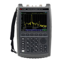
Keysight N9917A User Manual (566 pages)
FieldFox Analyzers
Brand:
Keysight
| Category:
Measuring Instruments
| Size: 6.73 MB
Table of Contents
Table of Contents
7
Overview
21
Models and Options
21
Accessories
22
Optional Accessories
22
Fieldfox Manuals, Software, and Supplemental Help
23
Conventions that Are Used in the Manual
23
Safety Notes
23
Preparing for Initial Use of Your New Fieldfox
25
Check the Shipment
25
Meeting Power Requirements for the AC/DC Adapter
25
Install the Lithium-Ion Battery
26
Battery Usage
26
Fieldfox ON/OFF Settings
27
Power Button LED Status
28
Fieldfox High Temperature Protection
28
How to Monitor the Internal Fieldfox Temperature
28
Temperature Control Mode
29
High-Temp Shutdown Warning (RTSA Mode Only)
31
Avoid Overpowering the Fieldfox
32
Take the Fieldfox Tour
33
Front Panel
33
Top Panel
36
Right Side Panel
36
Left Side Panel
38
Screen Tour
39
How to Enter Numeric Values
41
Multiplier Abbreviations
41
Connector Care
42
3 Cat (Cable and Antenna Test) Mode
43
Chapter 3 CAT (Cable and Antenna Test) Mode
43
CAT Mode Settings
45
How to Select CAT Mode
45
Measurement Selection
45
Quick Settings Table
46
Frequency Range
47
Scale Settings
47
Averaging
48
Smoothing
49
Single or Continuous Measure
49
Resolution (Number of Data Points)
50
Sweep Time
50
Output Power
51
Interference Rejection
51
Coupled Frequency
52
1-Port Cable Loss Measurements
53
How to Make a 1-Port Cable Loss Measurement
54
Return Loss Measurements
53
How to Measure Return Loss
53
2-Port Insertion Loss Measurements
55
How to Make Dtf Measurements
58
Chapter 4 DTF (Distance to Fault) Measurements How to Make DTF Measurements
58
DTF Measurement Settings
60
DTF Settings Table
60
DTF Measurement (Format)
60
DTF Start and Stop Distance
61
Frequency Mode
61
Coupled Frequency
62
Cable (Correction) Specifications
63
Window Settings
66
DTF Units
67
Calculated DTF Values
67
About Alias Faults
67
5 Tdr (Time Domain Reflectometry) - Option 215
69
TDR Measurement Settings
72
TDR Measurement (Format)
72
TDR Settings Table
72
TDR Start and Stop Distance
73
TDR Sweep
73
Frequency Mode
74
Cable (Correction) Specifications
75
Window Settings
78
TDR Units
79
Calculated TDR Values
79
About Alias Faults
80
How to Prevent Undersampling
81
6 Na (Network Analyzer) Mode
83
Chapter 6 NA (Network Analyzer) Mode
83
NA Mode Settings
85
About S-Parameters
85
Mixed-Mode S-Parameters
86
Parameter Conversion
87
Receiver Measurements
88
Multi-Trace Configurations
89
Quick Settings
90
Calibration Settings
91
Format
92
Frequency Range
93
Scale Settings
93
Magnitude Offset
94
Electrical Delay
95
Phase Offset
95
Averaging
96
IF Bandwidth
97
Smoothing
97
Single or Continuous Measure
98
Resolution (Number of Data Points)
98
Sweep Time
99
Triggering
99
Output Power
100
System Impedance (Z0)
101
Port Extensions
101
Velocity Factor
102
Big Marker Display States (a and B)
103
Increase Dynamic Range
105
7 Time Domain - Option 010
107
Time Domain - Option 010
108
Overview
109
Time Domain (Transform) Settings
110
Transform Settings Table
110
Start/Stop (Frequency Range) and Points
110
Stimulus (Mode)
111
Set Frequency Lowpass
111
Start/Stop Time
111
Distance Units
112
Window Layout
112
Transform Window
112
Line Loss and Velocity Factor
113
Data Chain
114
Trace Settings
115
Transform Enable
115
Gate Enable
115
Gating
116
How to Make Time Domain Gating Settings
117
Start, Stop, Center, and Span Gate Times
117
Gating Type
117
8 Calibration for Na, Cat, and VVM Modes
119
Chapter 8, "Calibration for NA, CAT, and VVM Modes
119
Calibration for NA, CAT, and VVM Modes
120
Why and When to Calibrate
120
Definitions
120
Calready
121
How to Perform a Calibration
121
Quickcal (N991Xa/2Xa/3Xa Only)
123
Mechanical Cal
125
Ecal
128
Simple Response Cals
130
View Cal
132
Calibration Type
132
Isolation Step
135
Waveguide Calibrations
135
Enhanced Response Optimization
137
Interpolation
138
Cal on ? - Questionable Accuracy
138
Compatible Mode Calibrations
138
Save the Calibration
138
Calready Properties
139
Verifying Calibration and Jumper Cable Integrity
140
Verify a Calibration
140
Test the Jumper Cable
140
Calibration Method Summary
141
SA (Spectrum Analyzer) Mode
143
Table of Contents
144
SA Mode Settings
146
How to Select SA Mode
146
Frequency Range
146
Radio Standard
148
Custom Radio Standards
148
Channel Selection
149
Reverse Swap
151
Scale and Units
151
External Gain
152
Attenuation Control
152
Preamplifier Control (Opt 235)
153
Check for Compressed Measurements
153
Field Strength Measurements
154
Using the Antenna/Cable Editor
156
Source Tracking Offset and Offset Reversal
158
Tune & Listen (AM/FM)
159
Independent Source/Tracking Generator
161
Resolution Bandwidth (Res BW)
163
Video Bandwidth (Video BW)
164
Sweep Type
164
IF Output
165
Sweep Acquisition
166
Very Long Sweep Times
167
Zero Span Measurements
167
Triggering
169
FFT Gating (Opt 238)
172
Single / Continuous / Restart
174
Points
174
Trace Display States (SA Mode)
175
Average Type
176
Average Count
176
Alignments
177
RF Burst Amplitude Alignment
182
Detection Method
184
Display Line
186
Noise Marker
187
Band/Interval Power Marker
187
Frequency Counter at Marker
188
Time Zero Fixed Marker
189
Audio Beep at Marker Power
189
Meas UNCAL Error
190
Old Data Indicator (*)
190
Channel Measurements
191
Radio Standards and Channel Measurements
191
Measurement Preset
191
Averaging
191
Traces
192
Channel Power (CHP)
192
RTSA (Real-Time Spectrum Analyzer) Mode-Option 350 (CPU2 Only)
203
Table of Contents
204
RTSA Mode Settings
205
How to Select RTSA Mode
205
Frequency Range
205
Scale and Units
206
External Gain
207
Attenuation Control
207
Preamplifier Control (Opt 235)
208
Check for Compressed Measurements
209
Spectrum Selection
209
Resolution Bandwidth (Res BW)
212
Triggering
213
TDR (Time Domain Reflectometry) - Option
215
Single / Continuous / Restart / Time Per DIV
216
Acq Time
217
Points (Not User Settable)
217
Trace Display States
218
Detection Method
219
Average Count, Show Density, Blue, and Red Percentage Limits
220
Alignments
221
Display Line
221
Average Count
221
Spectrogram Display
223
Spectrogram Display (RTSA Option)
223
Common Settings for Spectrogram
224
Record/Playback (RTSA Option)
225
About Sessions
225
Fieldfox Setting Changes During Record and Playback
226
About State and User Tags
227
How to Record a Session
228
How to Playback a Session
229
Recording Configuration
230
Record Source
231
Playback Configuration
232
Manage Sessions
232
Record Playback Example (RTSA Mode Only)
233
IQ Analyzer (IQA) - Option 351 (CPU2 Only)
235
Interference Analyzer (SA Mode) - Option
236
About I/Q Analyzer (IQA) Measurements
238
I/Q Analyzer (IQA) Mode Settings
239
How to Make Measurements Using the I/Q Analyzer Mode
239
How to Capture I/Q Data to a File
240
Advertisement
Advertisement
Related Products
Keysight N9913A
Keysight N9915A
Keysight N9916A
Keysight N9918A
Keysight FieldFox N9914A
Keysight N9911X
Keysight N9911X-110
Keysight N9911X-112
Keysight N9911X-113
Keysight N9911X-115
Keysight Categories
Measuring Instruments
Test Equipment
Multimeter
Control Unit
Portable Generator
More Keysight Manuals
Login
Sign In
OR
Sign in with Facebook
Sign in with Google
Upload manual
Upload from disk
Upload from URL