Sign In
Upload
Manuals
Brands
Keyscan Manuals
Control Unit
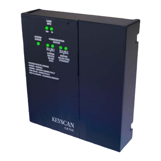
CA150
Keyscan CA150 Door PoE Equipped Manuals
Manuals and User Guides for Keyscan CA150 Door PoE Equipped. We have
1
Keyscan CA150 Door PoE Equipped manual available for free PDF download: Installation Manual
Keyscan CA150 Installation Manual (113 pages)
SINGLE DOOR POE
Brand:
Keyscan
| Category:
Control Unit
| Size: 1.5 MB
Table of Contents
Table of Contents
4
List of Figures
6
Foreword
8
About this Guide
8
Electrical Precautions
8
Tools
8
Software Requirements
8
About Powering the CA150
9
Program On-Board Ethernet Module
9
Configure the CA150 for Reverse Network Communication - License Required
9
Locate & Mount the CA150
11
Figure 1 - Typical Door Layout
11
Mounting Guidelines
12
Figure 2 - Remove the Right Cover
12
Figure 3 - Mounting the CA150
13
Figure 4 - CA150 Mount - Side View
14
Door Hardware & Readers
15
Door Lock Hardware
15
Door Contacts, Exit Buttons, Auxiliary Inputs
16
Figure 5 - Door Contacts, Exit Buttons, Pirs, & Auxiliary Inputs
16
Readers
17
Figure 6 - Typical Door Reader Connection
17
Cables & Grounding
18
Grounding
18
Figure 7 - Grounding Access Control Units and Cables
20
Terminate Wiring at the ACU
21
Poe
21
Output Relays
21
Figure 8 - Terminate Magnetic Lock under 500 Ma - Fail Safe
23
Figure 9 - Terminate Magnetic Lock over 500 Ma - Fail Safe
24
Figure 10 - Terminate Door Strike - 500 Ma or Less - Fail Safe
25
Figure 11 - Terminate Door Strike - over 500 Ma - Fail Safe
26
Figure 12 - Terminate Door Strike - Less than 500 Ma - Fail Secure
27
Figure 13 - Terminate Door Strike - over 500 Ma - Fail Secure
28
Terminate Input Wiring
29
Figure 14 - Terminate Input Wiring - Door Inputs (Contacts)
29
Figure 15 - Terminate Input Wiring - RTE Push Button
30
Figure 16 - Terminate Input Wiring - RTE PIR Motion Sensor
31
Figure 17 - Terminate Input Wiring RTE - PIR & Push Button
32
Figure 18 - Terminate Input Wiring - AI/SI Inputs
33
Terminate Reader Wiring at ACU
34
Figure 19 - Terminate Reader Wiring
34
Terminate Auxiliary Outputs with Hardware/Alarms
35
Figure 20 - Terminate Auxiliary Output
35
DIP Switch & Jumper Settings
36
System Configuration - DIP Switches S1.1 - S1.12
36
Figure 21 - System Configuration DIP Switches S1.1 - S1.12
38
Reader Configuration - DIP Switches S2.1 - S2.6
40
26-Bit Waiver of Liability
40
Advantage of Keyscan 36-Bit Proprietary Wiegand Format
40
Security Levels
40
Card Number Formats
40
Supported Keypad Wiegand Outputs
41
Figure 22 - Location of Reader Format DIP Switches S2.1 - S2.6
42
Figure 23 - Location of Wiegand Card Bit Counter Leds
46
Supervision Mode DIP Switches S2.7 & S2.8
47
Figure 24 - Supervision Mode DIP Switches S2.7 & S2.8
47
System Software Mode - DIP Switches S2.9 & S2.10
48
Figure 25 - System Software Mode S2.9 & S2.10 Location
48
Restore Default Settings - Jumper J1 Clear Memory
49
Figure 26 - Restore Default Settings (Clear Memory) J1 Location
49
System Reset - J6
50
Door & AUX Outputs - Powered/Unpowered
50
Figure 27 - Location of System Reset Jumper J6
50
Accessibility Output Relay
51
Figure 28 - Location of Door & AUX Relay Powered/Unpowered Jumpers
51
Figure 29 - Aux/Accessibility Switch S1.8
51
Figure 30 - Accessibility Output Relay Connections
52
Communication
53
Single Control Unit Communication Only
53
Keyscan RS-232 Data Cable
53
Figure 31 - RS-232 Data Cable Connections
54
Figure 32 - Communication - RS-232 Direct Serial
55
Figure 33 - Communication - USB Adaptor/Pc
56
Figure 34 - Communication - Ethernet
57
Power-Up & Test Voltages
58
System Power-Up
58
Figure 35 - Poe Connections
60
Figure 36 - Power Supply Wiring
61
Control Board Voltage Test Points
62
Figure 37 - Control Board Test Points - Voltages
62
Test Points - Communication Terminals
63
Figure 38 - Control Board Communication Test Points
63
Diagnostics
64
Communication Leds
64
System Status LED
65
Figure 39 - Communication Status Leds
65
Figure 40 - Location of System Status LED
66
Keyscan / HID Readers
67
Power Specifications
67
Figure 41 - Keyscan K-PROX2 (125 Khz)
70
Figure 42 - Keyscan K-VAN Proximity Reader (125 Khz)
71
Figure 43 - Keyscan K-KPR Keypad / Proximity Reader (125 Khz)
72
Figure 44 - Keyscan K-SMART Reader
73
Figure 45 - HID-5395 Wiring
74
Figure 46 - HID 5365 / 6005 Wiring
75
Figure 47 - HID 5455 Wiring
76
Figure 48 - HID 5375 Wiring
77
Figure 49 - HID 5355KP Wiring
78
Figure 50 - HID Iclass KEYR10
79
Figure 51 - HID Iclass KEYR40
80
Figure 52 - HID Iclass KEYRW400
81
Figure 53 - HID Iclass KEYRK40
82
Figure 54 - HID Iclass R10 Series
83
Figure 55 - HID Iclass R15 Series
84
Figure 56 - HID Iclass R40 Series
85
Figure 57 - HID Iclass RK40 Series
86
Indala Readers
87
Power Specifications
87
Figure 58 - Indala PX 603 and PX 605 Wiring
88
Figure 59 - Indala PX610 Wiring
89
Figure 60 - Indala PX 620 Wiring
90
Figure 61 - Indala PXK 501 Wiring
91
Program On-Board Ethernet Module
92
Before You Start Programming
92
Figure 62 - Temporary Connection for Programming the Ethernet Module
93
Configure CA150 for Reverse Network Communication
96
About Reverse Network Communication
96
Installation Coordination - Host & Remote Locations
96
Figure 63 - Example of Internet/Intranet/Wan with Router or End Point External IP
98
Figure 64 - LAN with no Public Exposure
99
Before You Start
100
Set System Configuration DIP Switches
101
Set IP Address on Access Control Board
101
Figure 65 - Location of System Configuration DIP Switches
101
Figure 66 - Temporary Programming Connection for Reverse Network
102
Program the CA150 On-Board Ethernet Module
103
CA150B Quick Reference
107
Figure 67 - CA150B Control Board
107
CA150B Specifications
109
Warranty
112
Index
113
Advertisement
Advertisement
Related Products
Keyscan CA250 Series
Keyscan CA4500 Series
Keyscan CA8500 Series
Keyscan CA250B/OCB-8
Keyscan CA8500B/OCB-8
Keyscan CA4500B/OCB-8
Keyscan CIM-LINK
Keyscan CA250B
Keyscan CA4500B
Keyscan CA8500B
Keyscan Categories
Control Unit
Scanner
Adapter
Motherboard
Card Reader
More Keyscan Manuals
Login
Sign In
OR
Sign in with Facebook
Sign in with Google
Upload manual
Upload from disk
Upload from URL