Sign In
Upload
Manuals
Brands
Kendro Manuals
Laboratory Equipment
HERAsafe KS 12
Kendro HERAsafe KS 12 Manuals
Manuals and User Guides for Kendro HERAsafe KS 12. We have
3
Kendro HERAsafe KS 12 manuals available for free PDF download: Service Instructions Manual, Operating Instructions Manual
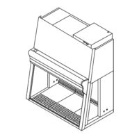
Kendro HERAsafe KS 12 Service Instructions Manual (118 pages)
Safety Cabinet
Brand:
Kendro
| Category:
Laboratory Equipment
| Size: 5.47 MB
Table of Contents
Table of Contents
3
1 General Notes
8
Safety Instructions for Service Work
8
Warranty
9
Explanation of Symbols
9
Symbols Used in the Service Instructions
9
Symbols on the Device
10
Additional Symbols on the Device (en Version)
11
Additional Symbols on the Device (NSF Version)
11
Safety Instructions for Repairs
12
Standards and Safety Regulations
14
2 Tools and Auxiliaries
15
Auxiliaries
15
List of Required Tools
15
3 Accessories
16
Exhaust System Accessories
16
Installing Exhaust System Accessories
16
Fig. 1 Exhaust System Accessories
16
Exhaust System Accessories for Disinfection
17
Fig. 2 Exhaust System Accessories for Disinfection
17
Fixed Rack
18
Height-Adjustable Rack
18
Fig. 3-A Installing the KS Racks
18
Height-Adjustable Rack with Electric Drive
19
Levelling the Device
19
Fig. 3-B Installing the Electrical KS Rack
19
Fig. 3-C Device Stands
19
Drain Valve (Optional)
20
Fig. 4 Drain Valve Installation
20
4 Media Connections
21
Installation Points for Media Valves (Optional) at the Sample Chamber Rear Panel
21
Fig. 5 Installation Points at the Rear Panel
21
Installation Points at the Sample Chamber Sidewalls
22
Fig. 6 Installation Points at the Sidewall
22
Installing Media Valves
23
Fig. 7 Media Valve Installation at the Rear Panel
23
Fig. 8 Media Valve Installation at the Sidewall
24
5 Lamps
25
Replacing the Luminescent Tubes
25
Replacing the Luminescent Tube Sockets
25
Fig. 9 Luminescent Tube and Socket Replacement
25
Replacing the Illumination Power Supply Unit
26
Replacing UV Lamps
26
Fig. 10 Illumination Power Supply Unit Replacement
26
Fig. 11 UV Lamp Replacement
26
Replacing the UV Lamp Power Supply Unit
27
Fig. 12 UV Lamp Power Supply Unit Replacement
27
6 Internal Outlets
28
Replacing Outlets for Accessories
28
Replacing the Disinfection Adapter
28
Fig. 13 Internal Outlet Replacement
28
7 Display Panel
29
Replacing the Display Panel Foil
29
Replacing the Display Panel
29
Fig. 14 Display Panel Foil Replacement
29
Replacing the Keyboard Foil
30
Replacing the Pilot Switch
30
Fig. 15 Keyboard Foil Replacement
30
Fig. 16 Pilot Switch Replacement
30
8 Side Window
31
Replacing the Side Window
31
Fig. 17 Side Window Replacement
31
9 Filter Components
32
Filter Application
32
Installing/Removing the Perforated Panel (Filter Protection)
33
Removing/Installing the Plenum Cover
33
Fig. 18 Perforated Panel (Filter Protection) Installation
33
Fig. 19 Plenum Cover
33
Replacing the Inlet Protection (Applications in EU / EMEA Only)
34
Fig. 20 Coarse Filter Replacement
34
Replacing the Exhaust Filter
35
Fig. 21 Exhaust Filter Replacement
35
Replacing the Downflow Filter
36
Replacing the Prefilter
36
Fig. 22 Downflow Filter Replacement
36
Fig. 23 Prefilter Replacement
37
10 Blowers
38
Replacing the Exhaust Blower
38
Fig. 24 Exhaust Blower Replacement
38
Replacing the Downflow Blower
39
Fig. 25 Downflow Blower Replacement
39
11 Pressure Sensors
40
Replacing Pressure Sensors
40
Fig. 26 Pressure Sensor Replacement
40
12 Front Door Components
41
Replacing the Front Door Assembly
41
Fig. 27 Front Door Hinge
41
Fig. 28 Hinge Bolt Removal
42
Replacing the Gas Struts
43
Replacing the Front Door Seal
43
Fig. 29 Gas Strut Removal
43
Fig. 30 Front Door Seal Replacement
43
Replacing the Front Frame Latch
44
Replacing the Safety Locks
44
Fig. 31 Front Frame Latch
44
Fig. 32 Safety Locks
44
Replacing the Front Window
45
Fig. 33 Remove Front Window
45
Fig. 34 Cable Retainers
45
Adjusting the Front Window
46
Fig. 35 Window Drive Mounting Bracket
46
Adjusting the Switch Points
47
Fig. 36 Position Switches
47
Replacing the Front Window Drive
48
Fig. 37 Window Drive Replacement
48
Replacing the Front Window Safety Feature Battery
49
Fig. 38 Battery/ Connecting Cable
49
13 Control Box Components
50
Replacing Control Box Electrical Components
50
Fig. 39 Control Box Electrical Components
50
Connecting the Alarm Contact
51
Fig. 40 Contact Function
51
Fig. 41 Example for External Connection
51
14 Device Control Programming
52
Setting the Remote Control
52
Program Structure
52
Fig. 42 Remote Control IR Address Setting
52
Service Level
53
Service Level Overview
53
Service Level Settings
55
Fig. 43 Service Level Display
55
Parameter Levels
57
Parameter Level Overview
57
Parameter Level Settings
59
Fig. 44 Parameter Level Display
59
Configuring the Switching States of a Device Control
61
Disinfection Level
63
Disinfection Level Overview
63
Disinfection Level Settings
64
Fig. 45 Disinfection Level Display
64
15 Auto-Calibration Routine
66
Function of the Auto-Calibration Routine
66
Starting the Auto-Calibration Routine
66
Automatic Interruption of the Auto-Calibration Routine
67
Manual Interruption of the Auto-Calibration Routine
67
Manual Abortion of the Auto-Calibration Routine
67
Manual Start of the Auto-Calibration Routine
68
Failures Upon Starting the Auto-Calibration Routine
68
Installation Test / Repeat Test
69
Classification of the Safety Cabinet
69
Test Terms
69
Extent of the Tests
70
Testing Equipment
70
4.1 Manufacturers in USA
70
Manufacturers in Europe
71
A.4.2 Manufacturers in Europe
71
Electrical Safety Test
72
HEPA Filter Leakage Test
74
Fig. a 1 HEPA Filter Leakage Test
75
Prefilter Element Leakage Test
76
Fig. a 2 Inflow Velocity Test Arrangement NSF 49
77
Fig. a 3 Inflow Air Volume Test
78
Inflow Velocity Test
80
Alternative Measurement of the Inflow Velocity in the Work Aperture (NSF 49)
80
Fig. a 4 Test Grid above the Exhaust Aperture
80
Alternative Measurement of the Inflow Velocity in the Work Aperture (en 12469)
82
Fig. a 4A Inflow Velocity Test Arrangement
82
The Work Aperture (NSF 49)
83
Fig. a 5 Inflow Air Volume Test
83
Calculating the Inflow Velocity (en 12469)
84
Test Grid above the Exhaust Aperture
85
Exhaust Airflow Volume Test
86
Downflow Velocity Test
87
Test in Accordance with NSF 49, Annex F
87
Fig. a 7 Downflow Velocity Test Arrangement in Accordance with NSF 49, Annex a
87
Fig. a 8 Downflow Velocity Test Arrangement in Accordance with en 12469 / DIN 12980
89
Airflow Pattern Test
91
A.10.1 Airflow Direction Test
91
A.10.2 Leakproofness Test for the Front Window
91
Fig. a 9 Airflow Pattern I
91
A.10.3 Leakproofness Test for Edges and Corners
92
Leakproofness Test for Seals and for the Upper Closing Edge
92
Fig. a 10 Airflow Pattern II
92
Noise Level Test
93
Fig. a 11 Noise Level Test
93
Lighting Intensity Test
94
Fig. A12 Lighting Intensity Test
94
Vibration Test
95
Fig. A13 Vibration Test
95
UV Intensity Test
96
A.15 Setting the Monitoring Devices
96
Downflow Velocity Alarm Values
96
Inflow Velocity Alarm Values
97
Decontamination with Gas
98
Disinfection with Formaldehyde
98
Procedure
98
Fig. B 1 Disinfection Hood
100
Installation Instructions, KSP Version
101
Sequence of the Installation
101
Fig. C 1 Prefilter Housing and Height Adjustment
101
Fig. C 2 Lifting Mechanism and Retaining Screws
102
Equipping the Prefilter Housing
103
Starting the Auto-Calibration Routine
103
Fig. C 3 Equipping the Prefilter Housing
103
Conducting the Installation Test
104
Marking the Device for Its Intended Purpose
104
Spare Parts
105
Parameter Lists
112
Service Parameter Overview
112
Overview Error Code of Front Window Function
113
Function Parameter Overview
114
Disinfection Parameter Overview
115
Failure Codes
116
Failure Code Overview
116
Test Report
117
Advertisement
Kendro HERAsafe KS 12 Operating Instructions Manual (70 pages)
Brand:
Kendro
| Category:
Laboratory Equipment
| Size: 2.14 MB
Table of Contents
Table of Contents
3
1 General Notes
6
Safety Instructions
6
Warranty
7
Explanation of Symbols
7
Symbols Used in the Operating Instructions
7
Symbols on the Device
8
Use of the Device
9
Correct Use
9
Incorrect Use
9
Standards and Safety Regulations
10
2 Delivery
11
Standard Components
11
Acceptance Inspection
11
Ambient Conditions
12
Room Ventilation
12
Correct Location
13
Installation in Series
13
Transport
13
Fig. 1
13
4 Description
14
Overall View
14
Safety System
17
Filter System
18
Filter System with Prefilters, Downflow Filter and Exhaust Air Filter / Version KS
18
Filter System with Prefilters, Downflow Filter and Exhaust Air Filter / Version KSP
19
Controls and Display
20
Fig. 6
20
Sample Chamber Access
21
Device Interfaces
22
UV Lamp Unit
24
Working Area
24
Working Area on the Workplate
24
Fig. 9
24
Initial Operation
25
Installing Unit and Accessories
25
Levelling the Cabinet
28
Activating the Remote Control
28
Inserting the Batteries
28
Fig. 12
28
Power Supply Connection
29
RS 232 Interface Connection
31
UV Connection
31
Fig. 14 UV Connection
31
Fig. 13
31
Installation Test
32
6 Handling and Control
33
Display
33
Functions of the Display Components
33
Fig. 15 Functions of the Display Components
33
Display During the Calibration Routine
34
Display in off Mode
34
Display in Work Mode
34
Power Interruption
34
Display and Functions after a Power Failure
34
Failure Messages
34
Description of the Operating Modes
35
Remote Control
37
Basic Functions
37
Basic Functions of the Remote Control
37
Fig. 16
37
Moving the Front Window to the Working Position
38
Silencing the Audible Alarm Signal
39
Activating and Deactivating the Internal Power Supply
40
Displaying the UV Disinfection Time
41
Activating and Deactivating the Potential-Free Contact (Optional)41
41
Switching the Cabinet to off Mode
41
Setting the Time
42
Displaying the Downflow Velocity
43
Displaying the Operating Hours of the HEPA Filters
43
Displaying the Kendro Performance Factor
44
Setting and Activating the Timer
45
Deactivating the Timer
46
Setting the UV Disinfection Time
47
Starting the UV Disinfection
47
Cancelling the UV Disinfection
48
Activating the Stop Watch
48
Pilot Switch
49
Moving the Front Window
49
Basic Functions of the Pilot Switch
49
Fig. 17
49
Silencing the Audible Alarm Signal
50
Switching the Device to off Mode
50
7 Operation
51
Hygiene Preparations for the Sample Chamber
51
Preparing the Sample Chamber
51
Response to Failure Messages
52
Work Rules
53
Sitting Posture
53
Fig. 18
53
8 Shut-Down
54
Interrupting an Operation
54
Shutting the Unit down
54
9 Cleaning and Decontamination
55
Decontamination Procedure
55
Wipe/Spray Disinfection
55
UV Disinfection after a Wipe/Spray Disinfection
57
UV Disinfection Using the Integral UV Lamps
57
UV Disinfection Using a Mobile UV Device
57
Disinfection with Formaldehyde
57
Cleaning the Exterior Surfaces
58
Cleaning the Floorpan
58
10 Maintenance
59
Inspection
59
Service
59
UV Lamps
59
Sample Chamber Illumination
60
Front Cover Seal Replacement
60
Retrofitting and Repairs
61
11 Disposal
62
Disposal Procedure
62
12 Technical Data
63
13 Device Log
68
14 Certificate of Decontamination
69
Kendro HERAsafe KS 12 Operating Instructions Manual (14 pages)
Electronically height-adjustable rack for safety cabinet
Brand:
Kendro
| Category:
Laboratory Equipment
| Size: 0.3 MB
Table of Contents
Table of Contents
3
Installation.8
8
Ambient Conditions.8
8
Start
9
Installation of the Rack.9
9
Connecting the Remote Control.10
10
Remote Control Buttons.11
11
Initial Operation of the Height Adjustment.11
11
Storing / Retrieving Positions.11
11
Troubleshooting.12
12
Shut-Down.12
12
Maintenance.12
12
Technical Data.13
13
Spare Parts.13
13
Advertisement
Advertisement
Related Products
Kendro HERAsafe KS 18
Kendro HERAsafe KSP 9
Kendro HERAsafe KSP 15
Kendro HERAsafe KSP 12
Kendro HERAsafe KSP 18
Kendro HERAsafe KS 15
Kendro HERAsafe KS 9
Kendro HERAsafe KS Series
Kendro HERAsafe KSP Series
Kendro HERAsafe KS
Kendro Categories
Laboratory Equipment
Washer
Accessories
Safes
More Kendro Manuals
Login
Sign In
OR
Sign in with Facebook
Sign in with Google
Upload manual
Upload from disk
Upload from URL