Sign In
Upload
Manuals
Brands
Keithley Manuals
Measuring Instruments
SourceMeter 2420
Keithley SourceMeter 2420 Manuals
Manuals and User Guides for Keithley SourceMeter 2420. We have
3
Keithley SourceMeter 2420 manuals available for free PDF download: User Manual, Quick Results Manual, Quick Start Manual
Keithley
SourceMeter 2400
User Manual
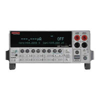
Keithley SourceMeter 2420 User Manual (594 pages)
SourceMeter 2400 Series Source Measure Unit
Brand:
Keithley
| Category:
Measuring Instruments
| Size: 2.79 MB
Table of Contents
Table of Contents
8
1 Getting Started
38
General Information
39
Warranty Information
39
Contact Information
39
Manual Addenda
39
Safety Symbols and Terms
39
Getting Started
39
Inspection
40
Options and Accessories
40
General Purpose Probes
40
Low Thermal Probes
41
Cables and Adapters
41
Rack Mount Kits
42
Carrying Case
42
Product Overview
42
Front and Rear Panel Familiarization
44
Front Panel Summary
44
Rear Panel Summary
46
Power-Up
47
Line Power Connection
47
Power-Up Sequence
48
System Identification
48
Line Frequency Setting
49
Front Panel Line Frequency
49
Remote Command Line Frequency
49
Table
49
Line Frequency Remote Commands
49
Fuse Replacement
50
Cooling Fan
50
Table 1-2 Power Line Fuse
50
Display
51
Display Format
51
EDIT Key
51
Remote Display Programming
52
Status and Error Messages
52
TOGGLE Key
52
Table
52
Basic Display Commands
52
Front Panel Tests
53
Default Settings
53
Restoring Setups
53
Saving and Restoring User Setups
53
Saving Setups
53
Factory Default Settings
54
Power-On Configuration
54
Table
54
Remote Setups
57
Table 1-5 Main Menu
58
Main Menu Tree
60
Rules to Navigate Menus
61
Toggling the Source and Measure Display Fields
62
Front Panel Control
63
Measurement Configuration Menus
64
Table
64
Figure
64
Source and Range Configuration Menus
65
Table
65
Figure
65
Rel, Filter, and Limit Configuration Menus
66
Table
66
Figure
66
Trigger Configuration Menu
68
Table
68
Sweep, Digits, Speed, and Data Store Configuration Menus
69
Table
69
Output and Display Configuration Menus
70
Table
70
Sweep, Digits, Speed, and Output Configuration Menus
71
Connection Overview
75
Remote Command Terminals Selection
76
Figure
77
Sensing Methods
78
Wire Remote Sensing
79
Guarding Methods
81
Ohms Guard
82
2 Wire Local Sensing
80
Guarded Ohms Measurements (Ohms Guard)
83
Sense and Guard Selections
84
Guard Selection
85
3 Basic Source-Measure Operation
87
Warning - Caution
87
Operation Overview
88
Source-Measure Capabilities
88
Table
89
Table 3-2 Compliance Limits
91
Compliance Commands
92
Table
92
Setting the Compliance Limit
92
Figure
93
Operation Considerations
94
NPLC Caching
95
Typical NPLC Cache Test Times
96
Front Panel V-Source Protection
97
Front Panel Source Delay
98
Table 3-4 Auto Source Delay
98
Basic Source-Measure Procedure
99
Step 3: Select Measurement Function and Range
101
Step 4: Turn Output on
102
Basic Source-Measure Commands
103
Table
103
Step 6: Turn Output off
103
Basic Source-Measure Programming Example
104
Table
104
Figure
105
Measure Only Programming Example
106
Table
106
Remote Command Measure Only
106
Sink Operation
107
Sink Programming Example
109
4 Ohms Measurements
110
Figure
111
Table
112
Auto Ohms Default Test Currents
112
Ohms Measurement Methods
112
Selecting Ohms Measurement Method
113
Manual Ohms Measurements
114
Ohms Sensing
116
Sense Selection
117
Offset-Compensated Ohms
118
Offset-Compensated Ohms Procedure
119
Ohms Source Readback
120
Remote Commands for Basic Ohms Measurements
121
Table
121
Remote Ohms Programming
121
Auto Ohms Programming Example
122
5 Pulse Mode Operation (Model 2430 Only)
124
Figure
125
Pulse Characteristics
126
Pulse Width
127
Pulse Width Delay
128
Pulse Delay
129
Auto Zero
130
Pulse-Only
131
Pulse Energy Limitations (10A Range)
132
Pulse Mode Configuration
133
Disable/Enable Auto Zero
134
Basic Pulse Mode Operation
135
Step 4: Select Source
136
Step 7: Turn Output on
137
Table
138
Basic Pulse-Measure Commands
138
Remote Command Pulse-Measure Operation
138
Table
139
Basic Pulse Programming Example
139
Pulse-Measure Programming Example
139
Filter
140
Offset-Compensated Ohms
141
Input Triggers
142
Turning Source on
143
6 Source-Measure Concepts
144
Table
146
Maximum Compliance Values
146
Compliance Examples
147
Table 6-2 Compliance Examples
148
Determining Compliance Limit
148
Overheating Protection
149
Power Equations to Avoid Shutdown
150
Model 2410 Sourcemeter
151
Models 2425 and 2430 Sourcemeters
152
Source-Delay-Measure Cycle
153
Figure
154
Sweep Waveforms
155
Operating Boundaries
157
Model 2400 Sourcemeter
158
Model 2410 Sourcemeter
159
Model 2420 Sourcemeter
160
Models 2425 and 2430 Sourcemeters
161
Model 2440 Sourcemeter
163
Table 6-1 Compliance Limits
146
I-Source Operating Boundaries
164
Voltage Compliance Boundaries
167
V-Source Operating Boundaries
169
Current Compliance Boundaries
171
Figure 6-13 V-Source Limit Lines
171
Figure 6-16 Source
171
Figure 6-14 V-Source Operating Examples
172
Source I Measure I and Source V Measure V
173
Basic Circuit Configurations
174
Figure 6-15 Source I
174
Source V
175
Figure 6-17 Measure Only (V or I)
176
Guard
177
Ohms Guard
178
Figure 6-18 High-Impedance Measurements
179
Figure 6-19 In-Circuit Ohms Measurements
180
Guard Sense
181
Figure 6-20 In-Circuit Ohms Measurements Using Guard Sense
182
Data Flow
183
Figure 6-21 Data Flow Front Panel
184
Buffer Considerations
185
Changing MATH Function
186
Manual Ranging
190
Figure
191
Limits Evaluation
192
Table 7-1 Range and Digits Commands
193
Table 7-2 Range and Digits Programming Example
193
Figure
194
Figure
195
Table 7-3 Speed Commands
195
Figure
196
Figure
197
Figure 7-2 Moving Average and Repeating Filters
198
Figure
199
Table 7-4 Filter Commands
199
Filter Programming Example
200
Relative
203
8 Relative and Math
204
Table
204
Rel Programming Example
204
Remote Rel Programming
204
Math Operations
205
Varistor Alpha
206
Figure
207
Figure
208
Table 8-3 Math Commands
208
Table 8-1 Rel Commands
204
Table
209
Math Programming Example
209
Commands for User-Defined Math Functions
210
Voltage Coefficient Programming Example
209
Table
210
User-Defined Math Function Programming Example
211
Data Store Overview
213
Timestamp
214
Average
215
9 Data Store
216
Timestamp Accuracy
216
Table 9-1 Data Store Commands
217
Remote Command Data Store
217
Table 9-2 Data Store Example
218
Sweep Operation
220
Sweep Types
221
Figure 10-1 Linear Staircase Sweep
222
Figure 10-2 Logarithmic Staircase Sweep (Example 5-Point Sweep from 1 to 10 Volts)
223
Table
224
Custom Sweep
224
Logarithmic Sweep Points
224
Custom Sweep Examples
225
Figure 10-3 Custom Pulse Sweep
225
Source Memory Sweep
226
Saving Multiple Source Memory Sweeps
227
Table
228
Source Memory Saved Configurations
228
Table 10-2 Source Memory Saved Configurations
228
Sweep Branching
229
Diode Test Example
231
Configuring and Running a Sweep
233
Figure 10-7 Sweep Configuration Menu Tree
234
Setting Delay
235
Performing a Linear Staircase Sweep
236
Performing a Log Staircase Sweep
237
Performing a Custom Sweep
238
Performing a Source Memory Sweep
240
Table
241
Linear and Log Staircase Sweep Commands
241
Remote Sweep Operation
241
Figure 10-8 Connections for Diode I-V Tests
242
Figure 10-9 Diode I-V Curve
242
Table 10-4 Staircase Sweep Programming Example (Diode Test)
243
Table 10-5 Custom Sweep Commands
243
Custom Sweep Programming Example
244
Table
244
Source Memory Sweep Commands
244
Table 10-8 Source Memory Sweep Programming Example
245
Sweep Branching Program Example
246
Pulse Mode Sweeps (Model 2430 Only)
251
Front Panel Pulse Mode Sweep Procedure
252
Figure 10-10 Pulse Mode Linear Staircase Sweep
253
Pulse Mode Linear Staircase Sweep Programming Example
253
Remote Pulse Mode Sweep Operation
253
11 Triggering
254
Remote Trigger Commands
255
Front Panel Trigger Operation
255
Figure 11-1 Front Panel Trigger Model
256
Arm Layer
257
Trigger Layer
258
Counters
259
Bench Defaults
260
Configuring Triggering
261
Figure 11-2 Trigger Configuration Menu Tree
263
Remote Trigger Operation
264
Figure 11-3 Remote Trigger Model
265
Event Detection
266
Trigger Layer
267
Figure 11-4 Measure Action
268
Counters
269
GPIB Defaults
270
Remote Trigger Commands
271
Figure 11-5 Rear Panel Pinout
272
Figure 11-6 Trigger Link Input Pulse Specifications
272
Figure 11-7 Trigger Link Output Pulse Specifications
273
Figure 11-8 Trigger Model for Front Panel Trigger Example
275
External Trigger Example
276
Figure 11-10 Trigger Link Connections
277
Instrument Configurations
278
Operation
279
Figure 11-9 DUT Test System
276
Operation Model for Triggering Example
280
Remote Trigger Example
281
Table 11-2 Commands for Remote Triggering Example
281
Trigger Model for Remote Trigger Example
282
Pulse Mode Triggering (Model 2430)
283
Pulse Mode Trigger Model (Front Panel Operation)
284
Pulse Mode Trigger Model (Remote Operation)
285
Idle
286
Output Triggers
287
Limit Testing
288
12 Limit Testing
289
Figure 12-1 Limit Tests
289
Types of Limits
289
Pass/Fail Information
290
Limit 2, Limit 3, and Limit 5-12 Tests
291
Operation Overview
292
Figure
293
Figure 12-3 Immediate Binning
294
Figure 12-4 End Binning
294
Pass Condition
295
Sorting Mode
296
Figure
297
Binning Systems
298
Digital Output Lines
299
Category Pulse Component Handler
300
Basic Binning Systems
301
Multiple-Element Device Binning
302
Binning System Multiple-Element Devices
303
Digital Output Clear Pattern
304
Auto-Clear Timing
305
Configuring and Performing Limit Tests
306
Performing Front Panel Limit Tests
308
Step 3: Configure Limit Tests
309
Table 12-1 Limit Commands
310
Remote Limit Testing
310
Figure 12-6 Handler Interface Connections
298
Commands to Control Digital I/O Port for Limit Testing
311
Limit Test Programming Example
311
Figure 12-11 Diode Pass/Fail Limits
312
Table 12-3 Limits Test Programming Example
313
Table 12-4 Limit Test Results Summary
313
Digital I/O Port, Safety Interlock, and Output Configuration
314
13 Digital I/O Port, Safety Interlock, and Output Configuration
315
Figure 13-1 Digital I/O Port
315
Figure 13-2 Sink Operation
316
SOT Line
316
Figure 13-3 Source Operation
317
Remote Digital Output Control
318
Table 13-1 Digital Output Line Settings
318
Figure
319
Front Panel Output Configuration
320
Output-Off States
321
Zero
322
Output-Off States and Inductive Loads
323
Output Configuration Commands
324
Remote Output Configuration
324
Output Configuration Programming Example
325
Remote Operations
326
Differences: Remote Vs. Local Operation
327
Remote-To-Local Transition
328
Figure 14-1 IEEE-488 Connector
329
Figure 14-2 IEEE-488 Connections
330
Primary Address
331
Table 14-1 General Bus Commands
332
LLO (Local Lockout)
333
SPE, SPD (Serial Polling)
334
Talk
335
14 Remote Operations
329
Programming Syntax
336
Query Commands
338
Long-Form and Short-Form Versions
339
Program Messages
340
Command Path Rules
341
Response Messages
342
RS-232 Interface Operation
343
Terminator
344
RS-232 Connector Pinout
345
RS-232 Interface Connector
345
Error Messages
346
Status Structure
348
Figure
349
Table 14-3 PC Serial Port Pinout
345
Figure
350
15 Status Structure
350
Common and SCPI Commands to Reset Registers and Clear Queues
351
Figure 15-2 16-Bit Status Register
352
Data Format Commands for Reading Status Registers
353
Status Byte and Service Request (SRQ)
354
Status Byte Register
355
Service Request Enable Register
356
Status Byte and Service Request Enable Register Commands
357
Status Byte Programming Example
357
Status Register Sets
358
Figure 15-4 Standard Event Status
359
Operation Event Register
359
Figure 15-5 Operation Event Status
360
Measurement Event Register
360
Figure 15-6 Measurement Event Status
361
Questionable Event Register
362
Condition Register Commands
363
Event Register Commands
363
Condition Registers
363
Event Enable Registers Commands
364
Program and Read Register Programming Example
365
Error Queue
366
Table 15-9 Error Queue Commands
367
Programming Example — Read Error Queue
367
16 Common Commands
368
Command Summary
369
Table 16-1 IEEE-488.2 Common Commands and Queries
369
Command Reference
370
Table 16-2 *OPC Programming Example
371
SAV, *RCL Programming Example
372
TRG Programming Example
373
WAI — Wait-To-Continue
374
17 SCPI Signal Oriented Measurement Commands
376
Figure
377
Signal Oriented Measurement Command Summary
377
Acquiring Readings
378
Sense[1]]:Data[:Latest]?
379
Measure[:<Function>]?
380
18 SCPI Command Reference
382
Reference Tables
383
Calculate Command Summary
384
Display Command Summary
389
Format Command Summary
390
Output Command Summary
390
Table 18-5 Route Command Summary
391
Table 18-6 Sense Command Summary
391
Source Command Summary
394
Status Command Summary
399
System Command Summary
400
Table 18-10 Trace Command Summary
402
Table 18-11 Trigger Command Summary
403
Calculate Subsystems
405
Program Examples
407
Delete[:Selected] <Name>
410
Define Math Expression
411
Enable and Read Math Expression Result
414
Latest?
415
Null Feed Reading
416
Latest?
417
Source2 <Nrf> |<NDN>
418
Pass:source2 <Nrf> | NDN
420
Fail?
421
Fail:source2 <Nrf> | <NDN>
422
Fail:smlocation <Nrf> | NEXT
423
Bcontrol <Name>
424
Clear Test Results
425
Acquire Statistic
426
Display Subsystem
427
Attributes?
428
Define :TEXT Messages
429
Format Subsystem
430
Figure 18-2 IEEE-754 Single Precision Data Format (32 Data Bits)
431
Data Elements
432
Source2 <Name>
436
Byte Order
437
Output Subsystem
438
Interlock Control
439
Route Subsystem
440
Sense1 Subsystem
441
ON] <Function List>
442
Count?
443
Resistance:mode <Name>
444
Select Measurement Range
445
Upper] <N>
446
Select Auto Range
448
Ulimit <N>
449
Rsynhronize <B>
450
Tripped?
451
Configure and Control Filter
452
State] <B>
453
Auto
454
MODE] <Name>
455
Select Range
456
AUTO <B>
458
Triggered[:Amplitude] <N>
460
Set Voltage Limit
461
Set Delay
464
Configure Voltage and Current Sweeps
465
Spacing <Name>
466
Center <N>
468
STEP <N>
469
Points <N>
471
Direction <Name>
472
Append <Nrf List>
473
Points?
474
SAVE <Nrf>
475
Points <Nrf>
476
Recall <Nrf>
477
Voltage List
478
Current List
479
Soak Time
480
Delay <N>
481
MODE <Name>
482
Bstate <B>
483
AUTO <B>
484
Status Subsystem
485
Select Default Conditions
486
Disable <List>
487
Control Remote Sensing
488
Select Guard Mode
489
Control Beeper
490
Control Auto Zero
491
Select Power Line Frequency Setting
492
Error Queue
493
Simulate Key Presses
494
Figure 18-3 Key-Press Codes
495
Read Version of SCPI Standard
496
Query Timestamp
497
Auto Range Change Mode
498
Clear
499
FEED <Name>
500
Trigger Subsystem
501
Abort Source/Measure Cycle
502
Delay <N>
503
Source <Name>
504
Timer <N>
505
Iline <Nrf>
506
Output <Event List>
507
Specifications
509
Status and Error Messages
520
Introduction
521
Table B-1 Status and Error Messages
522
Eliminating Common SCPI Errors
527
Query UNTERMINATED"
528
Introduction
531
Fetch?
532
Calculate[1]:Data?
533
IEEE-488 Bus Overview
534
Introduction
535
500 D IEEE-488 Bus Overview
536
Bus Description
536
Figure D-1 IEEE-488 Bus Configuration
537
Bus Lines
538
Figure D-2 IEEE-488 Handshake Sequence
539
IEEE-488 Bus Command Summary
540
Bus Commands
540
Uniline Commands
541
Addressed Multiline Commands
542
Common Commands
543
Table D-2 Hexadecimal and Decimal Command Codes
543
Figure D-3 Command Codes
544
Table D-3 Typical Addressed Multiline Command Sequence
545
Table D-4 Typical Addressed Common Command Sequence
545
Typical Command Sequences
545
Table D-5 IEEE Command Groups
546
Sourcemeter Interface Function Codes
547
Introduction
551
Table E-1 IEEE-488 Documentation Requirements
552
IEEE-488 and SCPI Conformance Information
553
Table E-2 Coupled Commands
553
F Contact Check Function
554
100 C Data Flow
555
Introduction
555
Block Diagram
556
Operation
557
Table F-1 Recommended Contact Resistance Threshold Values
558
Contact Check Threshold Resistances
558
Trigger Model Operation
559
Limit Test Sequence
560
Figure F-5 Grading Mode Contact Check Limit Testing
561
Figure F-6 Sorting Mode Contact Check Limit Testing
562
Binning Failure Indications (Grading Mode)
563
Contact Check Menu Selections
564
Auto Clear Off, Immediate Binning
564
Using Contact Check
565
Using Event Detection with Contact Check
566
Contact Check Remote Commands
567
Contact Check Programming Example
569
Contact Check Command Reference
570
Fail?
571
Configure and Control Contact Check Event Detection
572
Contact Check Defaults
573
TOUT <Nrf>
573
GPIB 488.1 Protocol
574
Introduction
575
Protocol Differences
576
NRFD Hold-Off
577
Trigger-On-Talk
578
Table G-1 SCPI/488.1 Reading Speed Comparisons for Measure-Only Sweep Operation (Rdgs/Sec)
579
Table G-2 SCPI/488.1 Reading Speed Comparisons for Source-Measure Sweep Operation (Rdgs/Sec)
579
Table G-3 SCPI/488.1 Reading Speed Comparisons for Source-Measure-Limit Test Sweep Operation (Rdgs/Sec)
580
Table G-4 SCPI/488.1 Reading Speed Comparisons for Source-Memory Sweep Operation (Rdgs/Sec)
580
SCPI/488.1 Reading Speed Comparisons for Measure-Only Single-Shot Operation (Rdgs/Sec
581
SCPI/488.1 Reading Speed Comparisons for Source-Measure Single-Shot Operation (Rdgs/Sec
581
SCPI/488.1 Reading Speed Comparisons for Source-Measure-Limit Test Single-Shot Operation (Rdgs/Sec
581
Advertisement
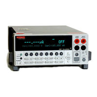
Keithley SourceMeter 2420 Quick Results Manual (53 pages)
Brand:
Keithley
| Category:
Measuring Instruments
| Size: 0.74 MB
Table of Contents
Table of Contents
7
Introduction
9
Source-Measure Capabilities
9
Figure 1 Front Panel
11
Figure 2 Rear Panel
11
Front and Rear Panels
11
Navigating Menus and Entering Numeric Data
12
Menu Navigation
12
Numeric Data Entry (EDIT Keys)
12
Editing Source and Compliance Values
12
Editing Keys
12
Editing Procedure
13
Toggling the Source and Measure Display Fields
13
Basic Connections
13
Front/Rear Terminals Selection
14
2 Wire Connections
14
Figure 3 2-Wire Connections
14
4 Wire Connections
15
Figure 4 4-Wire Connections
15
Cable Guard
16
Figure 5 Cable Guard Connections
16
Ohms Guard
16
Figure 6 Guarded Ohms Measurements
17
Basic Sourcemeter Operations
18
Source-Measure
18
Table 2 Source-Measure Procedure
19
Measure Only (V or I)
20
Table 3 Measure Only (V or I) Procedure
20
Measure Ohms
21
Table 4 Auto Ohms Measurement Procedure
21
Table 5 Manual Ohms Measurement Procedure
22
Remote Command Programming
23
Table 6 SCPI Commands; Source-Measure and Measure Only
24
Table 7 SCPI Commands; Measure Ohms
24
Table 8 Command Sequence for Source-Measure Example
25
Table 9 Command Sequence for Measure Current Only Example
25
Table 10 Command Sequence for Auto Ohms Example
26
Table 11 Command Sequence for Manual Ohms Example
26
Remote Command Programming
18
Settings to Optimize Performance
27
Range
27
Speed
27
Digits
28
Filter
28
Rel (Nulling Offsets)
29
Remote Command Programming
30
Table 12 SCPI Commands; Speed, Digits, Filter, and Rel
30
Features to Enhance DUT Testing
31
Data Store
31
Table 13 SCPI Commands; Data Store
32
Table 14 Command Sequence for Data Store Example
32
Sweep Operation
33
Figure 8 Logarithmic Staircase Sweep (Example)
34
Figure 9 Custom Pulse Sweep (Example)
35
Performing Sweeps
37
Table 15 SCPI Commands; Sweeping
39
Figure 7 Linear Staircase Sweep
40
Table 16 Command Sequences for Sweep Examples
40
Limit Testing
42
Table 17 SCPI Commands; Basic Non-Binning Limit Testing
43
Math Functions
44
Table 18 Command Sequence for Limit 2 Test Example
44
Table 19 SCPI Commands; Built-In Math Functions
47
Table 20 Command Sequence for Power Measurement Example
47
Pulse Mode (Model 2430 Only)
48
Figure 10 Pulse-Measure Timing
48
Table 21
52
SCPI Commands; Select and Configure Pulse Mode
52
Command Sequence for Pulse Mode Example
52
Keithley SourceMeter 2420 Quick Start Manual (46 pages)
SourceMeter 2400 series Source Measure Unit
Brand:
Keithley
| Category:
Measuring Instruments
| Size: 0.39 MB
Table of Contents
Safety Precautions
3
Table of Contents
5
Introduction
6
Introduction
7
Source-Measure Capabilities
7
Front and Rear Panels
8
Navigating Menus and Entering Numeric Data
9
Menu Navigation
9
Numeric Data Entry (EDIT Keys)
9
Editing Source and Compliance Values
9
Editing Keys
9
Editing Procedure
10
Toggling the Source and Measure Display Fields
10
2 Wire Connections
11
Basic Connections
11
Front/Rear Terminals Selection
11
4 Wire Connections
12
Cable Guard
13
Ohms Guard
14
Basic Sourcemeter Operations
15
Source-Measure
15
Measure Only (V or I)
16
Measure Ohms
17
Remote Command Programming
19
Scpi Commands
20
Programming Examples
20
Remote Command Programming
15
Settings to Optimize Performance
22
Range
22
Speed
23
Digits
23
Filter
23
Rel (Nulling Offsets)
24
Remote Command Programming
25
Features to Enhance DUT Testing
25
Data Store
25
Sweep Operation
27
Performing Sweeps
31
Limit Testing
35
Math Functions
38
Pulse Mode (Model 2430 Only)
41
Advertisement
Advertisement
Related Products
Keithley 2461
Keithley SourceMeter 2400
Keithley SourceMeter 2410
Keithley SourceMeter 2425
Keithley SourceMeter 2440
Keithley SourceMeter 2400-LV
Keithley SourceMeter 2401
Keithley SourceMeter 2430
Keithley SourceMeter 2460
Keithley 2430-C
Keithley Categories
Measuring Instruments
Multimeter
Test Equipment
Power Supply
Switch
More Keithley Manuals
Login
Sign In
OR
Sign in with Facebook
Sign in with Google
Upload manual
Upload from disk
Upload from URL