Sign In
Upload
Manuals
Brands
KAESER Manuals
Air Compressor
M100
KAESER M100 Manuals
Manuals and User Guides for KAESER M100. We have
1
KAESER M100 manual available for free PDF download: Operator's Manual
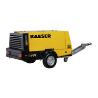
KAESER M100 Operator's Manual (384 pages)
Screw Compressor
Brand:
KAESER
| Category:
Air Compressor
| Size: 16.32 MB
Table of Contents
Table of Contents
3
Regarding this Document Using this Document
13
Further Documents
13
Copyright
13
Symbols and Labels
13
Warnings
13
Tab. 1 Danger Levels and Their Definitions (Personal Injury)
13
Potential Damage Warnings
14
Other Alerts and Their Symbols
14
Tab. 2 Danger Levels and Their Definition (Damage to Property)
14
Technical Data Nameplate
16
Options
16
Tab. 3 Nameplate
16
Compressed Air Treatment Devices
17
Tool Lubricator
17
Compressed Air Distributor
17
Tab. 4 Options Label
17
Tab. 5 Compressed Air Treatment Options
17
Tab. 6 Tool Lubricator Option
17
Check Valve Function
18
Proportional Controller
18
Low Temperature Equipment
18
Equipment for Fire Hazard Areas
18
Tab. 7 Compressed Air Distributor Option
18
Tab. 8 Check Valve Option
18
Tab. 9 Proportional Controller Option
18
Tab. 10 Low Temperature Equipment Options
18
Tab. 11 Optional Equipment for Fire Hazard Areas
18
Battery Isolating Switch
19
Chassis
19
Tab. 12 Battery Isolating Switch Option
19
Tab. 13 Chassis Options
19
Tab. 14 Options, Stationary Frame
19
Lighting
20
Generator
20
Sealed Floor Pan
20
Anti-Theft Device
20
Pedestrian Protection
20
Tab. 15 Lighting Options
20
Tab. 16 Generator Options
20
Tab. 17 Sealed Floor Pan Option
20
Tab. 18 Anti-Theft Device Option
20
Tab. 19 Pedestrian Protection Option
20
Instrument Panel Cover
21
Machine (Without Options)
21
Sound Pressure Level
21
Tightening Torques for Screws
21
Ambient Conditions
21
Additional Specifications
21
Tab. 20 Instrument Panel Cover Options
21
Tab. 21 Sound Pressure Level
21
Tab. 22 Tightening Torques for Screws (Property Class 8.8, Coefficient of Friction Μ = 0.12)
21
Tab. 23 Ambient Conditions
21
Chassis
22
Weight
22
Tires
22
Fig. 1 Example for Tire Information on the Side Wall
22
Tab. 24 Weight of the Machine
22
Wheel Nut/Bolt Tightening Torque
23
Towbar Tightening Torque
23
Compressor
23
Working Pressure and FAD
23
Compressed Air Outlet
23
Tab. 25 Tires
23
Tab. 26 Wheel Nut/Bolt Tightening Torque
23
Tab. 27 Towbar Tightening Torque
23
Tab. 28 Working Pressure and FAD
23
Tab. 29 Compressed Air Distributor
23
Safety Relief Valves
24
Temperature
24
Cooling Oil Recommendation
24
Tab. 30 Safety Relief Valve Activating Pressure
24
Tab. 31 Machine Temperatures
24
Tab. 32 Airend Discharge Temperature
24
Tab. 33 Cooling Oil Recommendations
25
Cooling Oil Charge
26
Engine
26
Engine Specification
26
Oil Recommendation
26
Tab. 34 Cooling Oil Recommendation (Food Processing)
26
Tab. 35 Cooling Oil Charge
26
Tab. 36 Engine Specification
26
Fuel Recommendation
27
Recommended Cooling Fluid
27
Fluid Volumes
27
Battery
27
Tab. 37 Engine Oil Recommendation
27
Tab. 38 Fluid Volumes
27
Tab. 39 Battery
27
Options
28
Air Treatment Options
28
Tab. 40 Road Breaker Lubricant Recommendation
28
Tab. 41 Fresh Air Filter Conditions
28
Low Temperature Equipment
29
Tab. 42 Interrelation between Compressed Air Treatment and Compressed Air Quality
29
Tab. 43 Environmental Conditions, Low Temperature Equipment
29
Tab. 44 Coolant Pre-Heater
29
Tab. 45 Recommended Antifreeze
29
Tab. 46 Battery, Low-Temperature Equipment
29
Generator (50 Hz Version)
30
Tab. 47 Generator Data
30
Tab. 48 Compressed Air Delivery with Generator in Operation (Generator Without FAD Limitation)
30
Tab. 49 Compressed Air Delivery with Generator in Operation (Generator with FAD Limitation)
31
Tab. 50 Connection Sockets
31
Tab. 51 Circuit Breaker
31
Tab. 52 Generator Operating Limits
32
Tab. 53 Maximum Three-Phase Mains Loading
32
Tab. 54 Maximum Single-Phase Mains Loading
32
Tab. 55 Power Reduction at Elevated Ambient Temperatures
32
Generator (60 Hz Version)
33
Tab. 56 Generator Data
33
Tab. 57 Compressed Air Delivery with Generator in Operation (Generator Without FAD Limitation)
33
Tab. 58 Compressed Air Delivery with Generator in Operation (Generator with FAD Limitation)
34
Tab. 59 Connection Sockets
34
Tab. 60 Circuit Breaker
34
Tab. 61 Generator Operating Limits
34
Tab. 62 Maximum Power Supply Load
35
Tab. 63 Power Reduction at Elevated Ambient Temperatures
35
Safety and Responsibility Basic Instructions
36
Specified Use
36
Incorrect Use
36
User's Responsibilities
36
Observe Statutory and Universally Accepted Regulations
36
Determining Personnel
37
Adherence to Inspection Schedules and Accident Prevention Regulations
37
Attachment of a "Hazardous Goods" Label
37
Dangers
38
Safely Dealing with Sources of Danger
38
Safe Machine Operation
41
Organizational Measures
44
Danger Areas
45
Safety Devices
45
Safety Signs
45
Tab. 64 Danger Areas
45
Fig. 2 Location of Safety Signs
46
Tab. 65 Safety Signs
48
Noise Control Requirements
49
Generator Operation
49
Comply with the Protective Measures against Dangerous Electric Current
49
Safe Generator Operation
49
Connecting Extension Cables
50
Do Not Exceed the Maximum Supply System Load
50
Perform Regular Generator Inspections
50
Emergencies
51
Correct Fire Fighting
51
Injury from Handling Operating Fluids/Materials
51
Warranty
52
Noise Emissions Warranty
52
Identifying the Effects of Improper Modifications
52
Environmental Protection
53
Design and Function Bodywork
54
Fig. 3 Overview Bodywork
54
Component Identification
55
Machine Function
55
Fig. 4 Right-Hand Door Opened
55
Fig. 5 Left-Hand Door Opened
55
Fig. 6 Machine Layout
56
Operating Modes and Control Mode
57
Operating Modes
57
MODULATING Control
57
Safety Devices
58
Monitoring Functions with Shutdown
58
Fig. 7 Stepless Regulation of FAD (Standstill)
58
Further Safety Devices
59
Fuel Level Monitoring
59
Options
59
Fig. 8 Fuel Level Monitoring
59
Compressed Air Treatment Options
60
Fig. 9 Compressed Air Options
60
Fig. 10 Tool Lubricator
62
Fig. 11 Principle Tool Lubricator
62
Low Temperature Equipment Options
63
Fig. 12 Coolant Pre-Heating
63
Optional Battery Isolating Switch
64
Fig. 13 Frost Protector
64
Options for Operating in Fire Hazard Areas
65
Fig. 14 Battery Isolating Switch
65
Generator Option
66
Tab. 66 Generator / Compressor Operation
66
Tab. 67 Generator Operating Modes
66
Fig. 15 Instrument Panel - Generator Control Box, 400 V AC
67
Fig. 16 Instrument Panel - Generator Control Box, 230 V AC
67
Transport Options
68
Fig. 17 Generator Instrument Panel - Control Box, 115 V, Single-Phase (50 Hz)
68
Fig. 18 Generator Instrument Panel - Control Box, 230 V, Single-Phase (60 Hz)
68
Sealed Floor Pan Option
70
Optional Anti-Theft Device
71
Pedestrian Protection Option
71
Fig. 19 Position of Service Openings in the Sealed Floor Pan
71
Fig. 20 Drain Points for Oil and Coolant from Engine and Compressor
71
Instrument Panel Cover Option
72
Installation and Operating Conditions
73
Ensuring Safety
73
Installation Conditions
73
Fig. 21 Minimum Distance from Excavations/Slopes and Walls
73
Installation
75
Ensuring Safety
75
Reporting Transport Damage
75
Fitting the Towbar
75
Fitting the Height Adjustable Towbar
76
Fig. 22 Height Adjustable Towbar, Fitted
76
Fig. 23 Fitting the Height Adjustable Towbar
76
Fitting a Non-Adjustable Tow Bar
77
Fig. 24 Non-Adjustable Tow Bar Fitted
77
Fig. 25 Fitting the Overrun Braking Mechanism of the Non-Adjustable Tow Bar
78
Adjusting the Chassis
79
Fig. 26 Fitting the Jockey Wheel of the Non-Adjustable Tow Bar
79
Adjusting the Towbar Height
80
Changing the Towing Eye/Ball Hitch
80
Fig. 27 Towbar Height Adjustment
80
Fig. 28 Changing the Towing Eye (Height-Adjustable Drawbar)
81
Fig. 29 Changing the Towing Eye/Ball Hitch (Fixed Height Towbar)
82
Fig. 30 Changing the Towing Eye (Fixed Height Towbar, USA Chassis Version)
83
Initial Start-Up Ensuring Safety
84
Before Initial Start-Up (or Recommissioning)
84
Instructions to be Observed before Commissioning or Recommissioning
84
Special Measures for Re-Commissioning after Storage
85
Checking Installation and Operating Conditions
85
Tab. 68 Measures for Re-Commissioning the Compressor after a Long Period of Storage
85
Tab. 69 Positioning and Operating Conditions Checklist
85
Low-Temperature Operation (Winter)
86
Starting Assistance
86
Fig. 31 Jumper Cable Connection Diagram
87
Starting up Low-Temperature Equipment
88
Fig. 32 Engine Coolant Pre-Heating
89
Fig. 33 Operating the Frost Protector
89
Activating the Generator
90
Fig. 34 Insulation Monitoring - 400 V AC, 3-Phase Generator
90
Fig. 35 Insulation Monitoring - 230 V AC, 3-Phase Generator
90
Tab. 70 Low-Temperature Equipment Checklist
90
Fig. 36 Insulation Monitoring - 115 V, Single-Phase Generator
91
Fig. 37 Insulation Monitoring - 230 V, Single-Phase Generator
91
Tab. 71 Test Instructions for a Generator with an Ground Short Detection Device
92
Operation
93
Ensuring Safety
93
Starting and Stopping
94
Fig. 38 Starting Instruments
94
Starting the Machine
95
Engine Pre-Heating
95
Allow the Machine to Run up to Operating Temperature
95
Switching to LOAD
96
Manually Setting the Discharge Pressure
96
Fig. 39 Label Referring to the Warm-Up Period When Ambient Temperatures Are below -50 °F
96
Shutting down the Machine
97
Fig. 40 Proportional Controller
97
Monitoring Fuel Level in the Fuel Tank
98
Operating the Tool Lubricator
98
Fig. 41 Setting the Tool Lubricator
98
Using the Low-Temperature Equipment
99
Pre-Warms the Engine Cooling Water
99
Operating the Machine with Frost Protector
100
Fig. 42 Frost Protector on and off
100
Operating the Battery Isolating Switch
101
Generator Operation
101
Fig. 43 Battery Isolating Switch
101
Note When Operating the Generator
102
Switching in the Generator
102
Switching off the Generator
102
Cleaning the Machine after Operation
103
Fault Recognition and Rectification
104
Basic Instructions
104
Engine Faults and Alarms
104
Engine Refuses to Start or Comes to a Stop
104
Engine Does Not Reach Full Speed
105
Indicator Lamp Remains on
105
Tab. 72 Alarm: Engine Refuses to Start or Comes to a Stop
105
Tab. 73 Alarm: Engine Does Not Reach Full Speed
105
Compressor Faults and Alarms
106
Working Pressure too High
106
Working Pressure too Low
106
Tab. 74 Indicator Lamp Remains on
106
Tab. 75 Fault: Working Pressure too High
106
Pressure Relief Valve Blowing off
107
Machine Overheating
107
Tab. 76 Fault: Working Pressure too Low
107
Tab. 77 Fault: Pressure Relief Valve Blowing off
107
Too Much Oil Residue in the Compressed Air
108
Oil Flows from the Compressor Air Filter after Shutdown
108
Tab. 78 Fault: Machine Overheating
108
Tab. 79 Fault: too Much Oil Residue in the Compressed Air
108
Tab. 80 Fault: Oil Flows from the Compressor Air Filter after Shutdown
108
High Moisture Content in the Compressed Air
109
Generator Faults and Alarms
109
There Is no Voltage or too Low a Voltage from the Generator
109
Generator Voltage too High
109
Tab. 81 Fault: High Moisture Content in the Compressed Air
109
Tab. 82 There Is no Voltage or too Low a Voltage from the Generator
109
Tab. 83 Generator Voltage too High
109
10.1 Maintenance
111
Ensuring Safety
111
Tab. 84 Advise Others that the Machine Is Being Serviced
111
Maintenance Schedules
112
Logging Maintenance Work
112
Maintenance Tasks after Commissioning
112
Regular Maintenance Tasks
113
Tab. 85 Maintenance Tasks after Commissioning
113
Tab. 86 Maintenance Intervals and Regular Maintenance Tasks
113
Tab. 87 Regular Machine Maintenance Tasks
116
Tab. 88 Regular Maintenance Task Options
117
Engine Maintenance
118
Water Cooler Maintenance
118
Fig. 44 Checking Coolant Level
119
Tab. 89 KAESER Coolant Mixture Table
120
Fig. 45 Draining the Coolant from the Radiator
122
Engine Air Filter Maintenance
123
Fig. 46 Draining the Coolant from the Radiator (Closed Floor Pan - Stationary Machine)
123
Fig. 47 Engine Air Filter Maintenance
124
Fig. 48 Cleaning the Filter Element
125
Fuel System Maintenance
126
Fig. 49 Fuel System Maintenance
126
Fig. 50 Bleeding the Fuel System
127
Fig. 51 Fuel Filter with Water Trap Maintenance
128
Fig. 52 Changing the Fuel Pre-Filter
129
Fig. 53 Fuel Micro-Filter Maintenance
129
Checking the Engine Oil Level
130
Engine Oil Filling and Topping up
131
Fig. 54 Checking the Engine Oil Level
131
Changing the Engine Oil
132
Fig. 55 Draining the Engine Oil
133
Fig. 56 Draining the Engine Oil (Closed Floor Pan - Stationary Machine)
134
Replace the Engine Oil Filter
135
Fig. 57 Changing the Oil Filter
135
Drive Belt Maintenance
136
Fig. 58 Belt Guard Attachment
136
Fig. 59 Checking the Drive Belt Seating
137
Fig. 60 Manually Checking the Belt Tension
137
Fig. 61 Changing/Tensioning the Drive Belt
138
Battery Maintenance
139
Fig. 62 Safety Signs - Warning Stickers on the Battery
139
Checking the Fastening of the Fuel Tank
142
Compressor Maintenance
142
Checking Cooling Oil Level
143
Fig. 63 Checking Cooling Oil Level
143
Cooling Oil Filling and Topping up
144
Changing the Cooling Oil
145
Fig. 64 Draining the Compressor Cooling Oil
146
Fig. 65 Draining the Oil from the Heat Exchanger
147
Fig. 66 Draining the Cooling Oil (Closed Floor Pan - Stationary Machine)
148
Replace the Compressor Oil Filter
149
Fig. 67 Changing the Oil Filter
149
Oil Separator Tank Dirt Trap Maintenance
150
Fig. 68 Oil Separator Tank Dirt Trap Maintenance
150
Changing the Oil Separator Cartridge
151
Fig. 69 Changing the Oil Separator Cartridge
152
Fig. 70 Changing the Oil Separator Cartridge (Option Ba)
154
Compressor Air Filter Maintenance
155
Fig. 71 Compressor Air Filter Maintenance
156
Fig. 72 Cleaning the Filter Element
157
Checking Safety Relief Valves
158
Cleaning the Cooler
158
Cleaning the Compressor Cooler and Engine Radiator
158
Cleaning the Compressed Air Aftercooler
159
Fig. 73 Cleaning the Compressor Cooler and Engine Radiator
159
Maintenance of Rubber Sealing Strips
160
Fig. 74 Cleaning the Compressed Air Aftercooler
160
Chassis Maintenance
161
Wheel Checks
161
Towbar Maintenance
161
Fig. 75 Towbar Maintenance
162
Fig. 76 Maintaining the Fixed Height Towbar
162
Fig. 77 Ball Coupling (EC Version)
163
Brake Maintenance
164
Fig. 78 Ball Coupling (USA Version)
164
Fig. 79 Checking the Brake Lining Thickness
165
Fig. 80 Brake System Adjustment
165
Fig. 81 Brake Rod Adjustment
166
Maintenance for Optional Items
167
Tool Lubricator Maintenance
167
Fig. 82 Tool Lubricator Maintenance
168
Cyclone Separator Maintenance
169
Fig. 83 Cleaning the Dirt Trap
169
Combination Filter Maintenance
170
Fig. 84 Filter Combination
171
Fig. 85 Combination Filter Maintenance
171
Fresh Air Filter Maintenance
174
Fig. 86 Fresh Air Filter Maintenance
174
Frost Protector Maintenance
177
Fig. 87 Filling the Frost Protector
177
Spark Arrestor Maintenance
178
Fig. 88 Cleaning the Spark Arrestor (Floor Pan with Service Openings)
178
Fig. 89 Cleaning the Spark Arrestor (Sealed Floor Pan)
179
Engine Air Intake Shut-Off Valve Maintenance
180
Fig. 90 Engine Air Intake Shut-Off Valve Maintenance
180
Generator Drive Belt Maintenance
181
Fig. 91 Securing the Belt Guard at the Generator
182
Fig. 92 Generator Belt Tensioning
183
Draining Liquid Accumulation Within the Machine
184
Documenting Maintenance and Service Work
186
Tab. 90 Maintenance Log
186
11 Spares, Operating Materials, Service
187
Note the Nameplate
187
Ordering Consumable Parts and Operating Fluids/Materials
187
Tab. 91 Compressor Consumables
187
Kaeser Air Service
188
Service Addresses
188
Replacement Parts for Service and Repair
188
Tab. 92 Consumable Engine Parts
188
Tab. 93 Replacement Parts, Combination Filter
188
Tab. 94 Replacement Parts, Fresh-Air Filter
188
12 Decommissioning, Storage and Transport
239
Commissioning
239
Temporary De-Commissioning
239
Tab. 95 "Temporarily Decommissioned" Information Notice
239
Long-Term Decommissioning and Storage
240
Tab. 96 Long-Term Decommissioning and Storage Checklist
240
Transport
241
Safety
241
Towing the Compressor on the Road
241
Tab. 97 Text for the Long-Term Decommissioned and Storage Information Notice
241
Fig. 93 Towing Position
243
Fig. 94 Ball Coupling (ALKO-EU)
244
Fig. 95 Wear Alert, Ball Coupling (ALKO-EU)
245
Tab. 98 Ball Coupling Wear Indicator
245
Fig. 96 Ball Coupling (ALKO-USA)
246
Fig. 97 Release the Parking Brake
246
Fig. 98 Automatic Jockey Wheel in Transport Position
247
Fig. 99 Safety Sign - Secure the Chocks
248
Fig. 100 Breakaway Cable Attachment
249
Fig. 101
249
Parking the Machine
250
Fig. 102 Warning "Injury Can Occur if the Towbar Is Allowed to Fall
250
Fig. 103 Towbar with Automatic Jockey Wheel
251
Fig. 104 Actuating the Parking Brake
251
Fig. 105 Safety Sign - Secure the Chocks
252
Transport with a Crane
253
Transport with a Forklift Truck
253
Transporting the Machine as Load
254
Fig. 106 Transporting Using a Forklift Truck
254
Storage
255
Fig. 107 Guys to Secure the Freight
255
Disposal
256
13 Annex
257
Identification
257
Pipeline and Instrument Flow Diagram (P+I Diagram)
257
Fig. 108 Identification
257
Dimensional Drawings
263
Dimensional Drawing, Chassis Options
263
Dimensional Drawing, Chassis Options
265
Dimensional Drawing, Chassis Options
267
Dimensional Drawing, Chassis Options
269
Dimensional Drawing, Stationary Version
271
Dimensional Drawing, Stationary Version
273
Wiring Diagrams
275
Electrical Diagram
275
Lighting and Signaling System Connection
289
Lighting and Signaling System Connection
297
Generator Electrical Diagram, 400V, 3-Ph
302
Generator Electrical Diagram, 230V, 3-Ph
311
Generator Electrical Diagram, 115 V, 2-Ph
320
Generator Electrical Diagram, 230 V, 2-Ph
329
Fuel Circulation Diagram
338
Assembly Diagrams - Chassis
341
Assembly Diagrams - Chassis EU Version
341
Assembly Diagrams - Chassis GB/US Version
343
Assembly Diagram Brake Rod
346
Operating Instructions for Compressed Air Filter (Combination Filter)
348
Operating Instructions for Compressed Air Filter (Fresh Air Filter)
369
Service Tasks - Generator
383
Advertisement
Advertisement
Related Products
KAESER M122
KAESER M43
KAESER M26
KAESER M27
KAESER M135 SIGMA CONTROL MOBIL
KAESER M 64
KAESER MOBILAIR M171
KAESER Aircenter SX 3
KAESER Aircenter SX 4
KAESER Aircenter SX 5
KAESER Categories
Air Compressor
Dryer
Dehumidifier
Water Filtration Systems
Compressor
More KAESER Manuals
Login
Sign In
OR
Sign in with Facebook
Sign in with Google
Upload manual
Upload from disk
Upload from URL