Sign In
Upload
Manuals
Brands
Juniper Manuals
Switch
QFX5100-48S
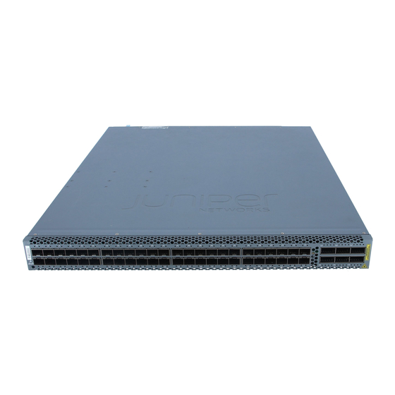
User Manuals: Juniper QFX5100-48S Ethernet Switch
Manuals and User Guides for Juniper QFX5100-48S Ethernet Switch. We have
3
Juniper QFX5100-48S Ethernet Switch manuals available for free PDF download: Hardware Documentation, Hardware Manual, Quick Start Manual
Juniper QFX5100-48S Hardware Documentation (669 pages)
Virtual Chassis Fabric
Brand:
Juniper
| Category:
Switch
| Size: 16.05 MB
Table of Contents
Table of Contents
3
About the Documentation
18
Documentation and Release Notes
18
Using the Examples in this Manual
18
Merging a Full Example
19
Merging a Snippet
20
Documentation Conventions
20
Documentation Feedback
23
Requesting Technical Support
23
Creating a Service Request with JTAC
24
Self-Help Online Tools and Resources
24
Overview
25
Virtual Chassis Fabric Overview
26
Understanding Virtual Chassis Fabric Configuration
28
Autoprovisioned Virtual Chassis Fabric Configuration
29
Virtual Chassis Fabric Setup
29
Nonprovisioned Virtual Chassis Fabric Configuration
30
Preprovisioned Virtual Chassis Fabric Configuration
30
Configuration File Management in a VCF
31
Logging into a Virtual Chassis Fabric
31
Understanding Interface Numbering
31
Virtual Chassis Fabric Hardware Overview
32
QFX5110 Overview
34
QFX5110 Hardware Overview
34
Benefits of QFX5110
34
QFX5110 Models Overview
35
QFX5110-48S Hardware
37
QFX5110-32Q Hardware
38
System Software
38
QFX5110-48S Port Panel
39
Switch Overview
39
Network Ports
40
Channelizing Interfaces
41
Virtual Chassis and Virtual Chassis Fabric
41
QFX5110-32Q Port Panel
42
Switch Overview
42
Network Ports
43
Channelizing Interfaces
44
Virtual Chassis and Virtual Chassis Fabric
45
QFX5100 Overview
46
QFX5100 Device Hardware Overview
46
QFX5100 Hardware
46
System Software
55
Port Panel of a QFX5100-24Q Device
56
Switch Ports
56
Channelizing Interfaces (Non-Qfabric)
57
Qfabric Systems
57
Virtual Chassis and Virtual Chassis Fabric
58
Port Leds
59
Port Panel of QFX5100-48S and QFX5100-48SH Devices
60
Port Panel of QFX5100-48T and QFX5100-48TH Devices
63
Port Panel of a QFX5100-96S Device
65
Channelizing Interfaces
66
Switch Ports
66
Virtual Chassis and Virtual Chassis Fabric Support
67
QFX3600 Overview
69
QFX3600 Device Overview
69
Software
70
Hardware
70
Front Panel of a QFX3600 Device
72
QFX3500 Overview
75
QFX3500 Device Overview
75
Hardware
76
Software
76
SFP+ Access Ports
77
QSFP+ Uplink Ports
78
Front Panel of a QFX3500 Device
80
EX4300 Overview
82
EX4300 Switches Hardware Overview
82
Benefits of the EX4300 Switch
83
EX4300 Switches First View
83
Software
83
24-Port EX4300 Switches
84
32-Port EX4300 Switches
86
48-Port EX4300 Switches
88
Uplink Modules
99
Virtual Chassis
102
Power Supplies
103
Fan Modules
104
EX4300 Switch Components
105
Planning
110
Site Preparation
111
Plan a Virtual Chassis Fabric Deployment | 87
111
CHAPTER 7 Sitepreparation
114
QFX5110 Site Preparation Checklist
114
Site Preparation Checklist for a QFX5100 Device
116
Site Preparation Checklist for a QFX3600 or QFX3600-I Device
117
Site Preparation Checklist for a QFX3500 Device
119
Site Preparation Checklist for EX4300 Switches
121
QFX5110 Environmental Requirements and Specifications
122
Environmental Requirements and Specifications for a QFX5100 Device
123
Environmental Requirements and Specifications for QFX3600 and QFX3600-I Devices
125
Environmental Requirements and Specifications for a QFX3500 Device
126
Environmental Requirements and Specifications for EX Series Switches
127
Rack and Cabinet Requirements
133
QFX5110 Rack Requirements
133
Rack Requirements for a QFX5100 Device
135
Rack Requirements for a QFX3600 or QFX3600-I Device
136
Rack Requirements for a QFX3500 Device
138
Rack Requirements
139
Cabinet Requirements for a QFX5100 Device
141
Device
141
Cabinet Requirements for a QFX3600 or QFX3600-I Device
142
Cabinet Requirements for a QFX3500 Device
143
Device
143
Cabinet Requirements
144
QFX5110 Clearance Requirements for Airflow and Hardware Maintenance
145
QFX5110 Clearance Requirements for
145
Clearance Requirements for Airflow and Hardware Maintenance for a QFX5100 Device
146
Clearance Requirements for Airflow and Hardware Maintenance for a QFX5100
146
Clearance Requirements for Airflow and Hardware Maintenance for a QFX3600 or QFX3600-I Device
147
Device
148
Clearance Requirements for Airflow and Hardware Maintenance for a QFX3500 Device
149
Clearance Requirements for Airflow and Hardware Maintenance for EX4300 Switches
150
Port and Interface Specifications
154
Console Port Connector Pinout Information
154
Console Port Connector Pinouts for the QFX Series
155
Management Port Connector Pinouts for the QFX Series
156
Mini-USB Port Pinout Specifications
157
USB Port Specifications for an EX Series Switch
157
USB Port Specifications for the QFX Series
158
Transceiver and Cable Specifications
160
Determining Transceiver Support for the QFX5110
160
Determining Interface Support for the QFX5100 Device
161
Determining Interface Support for the QFX3600 Device
164
Determining Interface Support for the QFX3500 Device
165
Pluggable Transceivers Supported on EX4300 Switches
167
Cable Specifications for QSFP+ and QSFP28 Transceivers
168
Cable Specifications for Console and Management Connections for the QFX Series
170
Calculating the Fiber-Optic Cable Power Budget for QFX Series Switches
171
Calculating the Fiber-Optic Cable Power Margin for QFX Series Switches
171
Management Cable Specifications
173
Understanding EX Series Switches Fiber-Optic Cable Signal Loss, Attenuation, and Dispersion
174
Attenuation and Dispersion in Fiber-Optic Cable
174
Signal Loss in Multimode and Single-Mode Fiber-Optic Cable
174
Understanding QFX Series Fiber-Optic Cable Signal Loss, Attenuation, and Dispersion
175
Signal Loss in Multimode and Single-Mode Fiber-Optic Cables
175
Attenuation and Dispersion in Fiber-Optic Cable
176
Planning QFX5100 Power Requirements
177
AC Power Specifications for a QFX5100 Device
177
AC Power Cord Specifications for a QFX Series Device
178
DC Power Specifications for a QFX5100 Device
180
Planning QFX5110 Power Requirements
182
QFX5110 AC Power Specifications
182
AC Power Cord Specifications for a QFX Series Device
183
QFX5110 DC Power Specifications
185
Planning QFX3600 Power Requirements
186
AC Power Specifications for a QFX3600 or QFX3600-I Device
186
AC Power Cord Specifications for a QFX Series Device
187
DC Power Specifications for a QFX3600 or QFX3600-I Device
189
CHAPTER 14 Planningqfx3500Powerrequirements
190
Table
190
AC Power Cord Specifications for a QFX Series Device
191
DC Power Specifications for a QFX3500 Device
193
Item
193
Typical Power Consumption
193
Maximum Power Consumption
193
Related Documentation
193
Describes the AC Power Specifications for a QFX3500 Device
193
Specification
193
Planning EX4300 Power Requirements
194
Planning QFX3500 Power Requirements
190
AC Power Specifications for a QFX3500 Device
190
CHAPTER 15 Planningex4300Powerrequirements
194
AC Power Supply in EX4300 Switches
194
Characteristics of an AC Power Supply
195
100-120 Vac
197
AC Power Supply Airflow
197
Operating Range
197
N+0 Redundancy Configuration of AC Power Supplies
198
N+N Redundancy Configuration of AC Power Supplies
201
AC Power Cord Specifications for an EX4300 Switch
204
DC Power Supply in EX4300 Switches
208
In this Section
208
Characteristics of a DC Power Supply
209
DC Power Supply Airflow
210
N+0 Redundancy Configuration of DC Power Supplies
211
N+N Redundancy Configuration of DC Power Supplies
212
Agency Approvals for EX Series Switches
214
Compliance
214
Agency Approvals for the QFX Series
215
Compliance Statements for EMC Requirements for EX Series Switches
216
Canada
217
Taiwan
217
European Community
218
Israel
218
Japan
218
FCC Part 15 Statement
219
Korea
219
United States
219
Nonregulatory Environmental Standards
220
Compliance Statements for EMC Requirements for the QFX Series
221
Canada
221
European Community
222
Israel
222
Japan
222
Korea
223
Nonregulatory Environmental Standards
223
Taiwan
223
United States
223
Compliance Statements for Acoustic Noise for EX Series Switches
224
Safety
226
General Safety Information
227
General Safety Guidelines and Warnings
227
Definitions of Safety Warning Levels
228
Fire Safety Requirements
231
Fire Suppression
231
Fire Suppression Equipment
231
Qualified Personnel Warning
232
Warning Statement for Norway and Sweden
233
Radiation and Laser Warnings
234
Radiation from Open Port Apertures Warning
235
Laser and LED Safety Guidelines and Warnings for the QFX Series
236
Class 1M Laser Product Warning
236
Class 1M Laser Radiation Warning
237
Unterminated Fiber-Optic Cable Warning
238
Installation and Maintenance Safety Information
241
CHAPTER 19 Installationandmaintenancesafetyinformation
242
Installation Instructions Warning
242
QFX5100 Installation Safety Guidelines
242
Chassis Lifting Guidelines for a QFX3600 or QFX3600-I Device
243
Chassis Lifting Guidelines for a QFX3500 Device
244
Chassis Lifting Guidelines for EX4300 Switches
244
Restricted Access Warning
246
Ramp Warning
248
Rack-Mounting and Cabinet-Mounting Warnings
248
Grounded Equipment Warning
254
Maintenance and Operational Safety Guidelines and Warnings
254
Battery Handling Warning
256
Jewelry Removal Warning
257
Lightning Activity Warning
259
Operating Temperature Warning
260
Product Disposal Warning
262
Wall-Mounting Warning for EX4300 Switches
263
CHAPTER 20 Powerandelectricalsafetyinformation
264
General Electrical Safety Guidelines and Warnings
264
Prevention of Electrostatic Discharge Damage
266
Action to Take after an Electrical Accident
267
AC Power Electrical Safety Guidelines
268
AC Power Disconnection Warning
269
DC Power Electrical Safety Guidelines
269
DC Power Disconnection Warning
271
DC Power Grounding Requirements and Warning
273
DC Power Wiring Sequence Warning
275
DC Power Wiring Terminations Warning
278
Multiple Power Supplies Disconnection Warning
281
TN Power Warning
282
Power and Electrical Safety Information
264
Before You Begin
284
Virtual Chassis Fabric Installation Overview
284
Installing a QFX5110 Switch
286
Standalone Installation Overview
286
Unpacking a QFX5110
287
Mounting a QFX5110 in a Rack
288
Before You Begin Rack Installation
289
Connect the QFX5110 to Earth Ground
291
Connecting AC Power to a QFX5110
292
Connecting DC Power to a QFX5110
295
Installing a QFX5100 Switch
300
QFX5100 Standalone Installation Overview
300
Unpack a QFX5100 Device
301
Mount a QFX5100 Device in a Rack or Cabinet
303
Before You Begin Rack Installation
303
Four-Post Procedure
305
Connecting Earth Ground to a QFX5100 Device
308
Connecting AC Power to a QFX5100 Device
309
Connecting DC Power to a QFX5100 Device
312
Connecting a QFX Series Device to a Management Console
317
Connecting a QFX5100 Device in a Virtual Chassis Fabric
319
Connecting a QFX5100 Device to a Network for Out-Of-Band Management
320
Installing a QFX3600 Switch
322
Installing and Connecting a QFX3600 or QFX3600-I Device
322
Unpacking a QFX3600 or QFX3600-I Device
323
Mounting a QFX3600 or QFX3600-I Device on Two Posts in a Rack or Cabinet
325
Mounting a QFX3600 or QFX3600-I Device on Four Posts in a Rack or Cabinet
327
Connecting Earth Ground to QFX3600 or QFX3600-I Devices
332
Connecting AC Power to a QFX3500, QFX3600, or QFX3600-I Device
333
Connecting DC Power to a QFX3500, QFX3600, or QFX3600-I Device
336
Connecting a QFX Series Device to a Management Console
341
Connecting QFX Series and EX Series Switches in a QFX Virtual Chassis
343
Before You Start
343
Valid Configurations
344
Cabling QFX3500 Switches in a QFX5100 Virtual Chassis
345
Cabling QFX3600 Switches in a QFX Virtual Chassis
346
Cabling a Mixed QFX Virtual Chassis
347
Connect a Device to a Network for Out-Of-Band Management
349
Installing a QFX3500 Switch
350
Installing and Connecting a QFX3500 Device
350
Unpacking a QFX3500 Device
351
Mounting a QFX3500 Device in a Rack or Cabinet
352
Before You Begin Rack Installation
353
Two Mounting Rails Procedure
354
Four Mounting Rails Procedure
356
Connecting Earth Ground to a QFX3500 Device
358
Connecting AC Power to a QFX3500, QFX3600, or QFX3600-I Device
360
Connecting DC Power to a QFX3500, QFX3600, or QFX3600-I Device
362
Connecting a QFX Series Device to a Management Console
367
Connecting QFX Series and EX Series Switches in a QFX Virtual Chassis
369
Before You Start
369
Valid Configurations
370
Cabling QFX3500 Switches in a QFX5100 Virtual Chassis
371
Cabling QFX3600 Switches in a QFX Virtual Chassis
372
Cabling a Mixed QFX Virtual Chassis
373
Connecting a QFX3500 Device to a Network for Out-Of-Band Management
375
Installing an EX4300 Switch
377
Installing and Connecting an EX4300 Switch
377
Unpacking an EX4300 Switch
378
Mounting an EX4300 Switch
379
Mounting an EX4300 Switch on Two Posts of a Rack or Cabinet
380
Mounting an EX4300 Switch on Four Posts of a Rack or Cabinet
383
Mounting an EX4300 Switch in a Recessed Position in a Rack or Cabinet
387
Mounting an EX4300 Switch on a Wall
387
Performing the Initial Configuration
392
Autoprovisioning a Virtual Chassis Fabric
392
Preprovisioning a Virtual Chassis Fabric
397
Configuring a Nonprovisioned Virtual Chassis Fabric
404
Cabling a Virtual Chassis Fabric
409
Connecting QFX5110 in a QFX5110 Virtual Chassis Fabric
409
Connecting a QFX5100 Device in a Virtual Chassis Fabric
411
Connecting a QFX3500 or QFX3600 Switch in a QFX5100 Virtual Chassis Fabric
413
Connecting EX Series Switches in a QFX5100 Virtual Chassis Fabric
415
Maintenance
417
Removing or Replacing a Device
418
Adding a Device to a Virtual Chassis Fabric
418
Adding a Leaf Device to an Autoprovisioned Virtual Chassis Fabric
419
Adding a Spine Device to an Autoprovisioned Virtual Chassis Fabric
421
Adding a Spine or Leaf Device to a Preprovisioned Virtual Chassis Fabric
423
Adding a Spine or Leaf Device to a Nonprovisioned Virtual Chassis Fabric
426
Removing a Device from a Virtual Chassis Fabric
429
Powering off a QFX5110
430
Powering off a QFX5100 Device
433
Powering off a QFX3600 Device
436
Powering off a QFX3500 Device
438
Removing a QFX5110 from a Rack
440
Removing a QFX5100 Device from a Rack or Cabinet
442
Removing a QFX3600 or QFX3600-I Device from a Rack or Cabinet
443
Removing a QFX3500 Device from a Rack or Cabinet
444
Replacing QFX5110 Components
446
Installing a Fan Module in a QFX5110
446
Removing a Fan Module from a QFX5110
447
Installing a Power Supply in a QFX5110
449
Removing a Power Supply from a QFX5110
451
CHAPTER 31 Replacingqfx5100Components
453
Installing and Removing QFX5100 Device Hardware Components
453
Installing a Power Supply in a QFX5100 Device
454
Removing a Power Supply from a QFX5100 Device
456
Installing an Expansion Module in a QFX5100 Device
458
Removing an Expansion Module from a QFX5100 Device
462
Installing a Fan Module in a QFX5100 Device
464
Removing a Fan Module from a QFX5100 Device
466
Replacing QFX5100 Components
453
Replacing QFX3600 Components
468
Installing and Removing QFX3600 or QFX3600-I Device Hardware Components
468
Removing a Power Supply from a QFX3600 or QFX3600-I Device
469
Installing a Power Supply in a QFX3600 or QFX3600-I Device
471
Removing a Fan Tray from a QFX3600 or QFX3600-I Device
473
Installing a Fan Tray in a QFX3600 or QFX3600-I Device
474
Replacing QFX3500 Components
476
Installing and Removing QFX3500 Device Hardware Components
476
Installing a Power Supply in a QFX3500 Device
477
Removing a Power Supply from a QFX3500 Device
479
Installing a Fan Tray in a QFX3500 Device
481
Removing a Fan Tray from a QFX3500 Device
483
Installing a Management Board in a QFX3500 Device
484
Removing a Management Board from a QFX3500 Device
486
Replacing EX4300 Components
488
Installing and Removing EX4300 Switch Hardware Components
488
Installing an AC Power Supply in an EX4300 Switch
489
Installing a DC Power Supply in an EX4300 Switch
491
Installing a Fan Module in an EX4300 Switch
493
Installing an Uplink Module in an EX4300 Switch
495
Install a Transceiver
497
Replacing Transceivers and Fiber-Optic Cables
500
Removing a Transceiver from a QFX Series Device
500
Remove a Transceiver
502
Installing a Transceiver in a QFX Series Device
505
Install a Transceiver
508
Disconnecting a Fiber-Optic Cable from a QFX Series Device
510
Disconnect a Fiber-Optic Cable
511
Connecting a Fiber-Optic Cable to a QFX Series Device
512
Connect a Fiber-Optic Cable
514
Routine Maintenance
515
Maintaining Fiber-Optic Cables in a QFX Series Device
515
How to Handle Fiber-Optic Cables
516
Viewing QFX5110 System Information
517
QFX5110 Chassis Status Leds
517
QFX5110 Management Port Leds
520
QFX5110 Network Port Leds
522
QFX5110 Fan Module LED
524
QFX5110 AC Power Supply Leds
525
QFX5110 DC Power Supply Leds
526
Viewing QFX5100 System Information
529
Chassis Status Leds on a QFX5100 Device
529
Management Port Leds on a QFX5100 Device
532
Access Port and Uplink Port Leds on a QFX5100 Device
534
Fan Module LED on a QFX5100 Device
537
AC Power Supply Leds on a QFX5100 Device
538
DC Power Supply Leds on a QFX5100 Device
540
Viewing QFX3600 System Information
542
Chassis Status Leds in the QFX3600 and QFX3600-I Device
542
Management Port Leds in the QFX3600 and QFX3600-I Device
544
Access Port and Uplink Port Leds on a QFX3600 or QFX3600-I Device
545
Fan Tray LED on a QFX3600 or QFX3600-I Device
546
AC Power Supply Leds on a QFX3500, QFX3600, or QFX3600-I Device
547
DC Power Supply Leds on a QFX3500, QFX3600, or QFX3600-I Device
549
Viewing QFX3500 System Information
551
Chassis Status Leds on a QFX3500 Device
551
Management Port Leds on a QFX3500 Device
553
Access Port and Uplink Port Leds on a QFX3500 Device
554
Fan Tray LED on a QFX3500 Device
556
AC Power Supply Leds on a QFX3500, QFX3600, or QFX3600-I Device
557
DC Power Supply Leds on a QFX3500, QFX3600, or QFX3600-I Device
558
Viewing EX4300 System Information
561
Dashboard for EX Series Switches
561
Graphical Chassis Viewer
562
System Information Panel
564
Health Status Panel
567
Capacity Utilization Panel
571
Alarms Panel
571
File System Usage
572
Chassis Viewer
572
Chassis Status Leds on EX4300 Switches
588
Network Port, Built-In QSFP+ Port, Uplink Port, and Uplink Module Port Leds on EX4300 Switches
590
Management Port Leds on EX4300 Switches
597
AC Power Supply Leds in EX4300 Switches
599
DC Power Supply Leds in EX4300 Switches
600
Troubleshooting
602
Restoring Junos os
603
Creating an Emergency Boot Device for QFX Series Switches
603
Performing a Recovery Installation
605
Recovering the Installation Using an Emergency Boot Device
608
Returning Hardware
610
Locating the Serial Number on a QFX5110 Device or Component
610
Listing the Chassis and Component Details Using the CLI
611
Locating the Chassis Serial Number ID Label on a QFX5110
612
Locating the Serial Number ID Labels on FRU Components
612
Locating the Serial Number on a QFX5100 Device or Component
614
Listing the Chassis and Component Details Using the CLI
614
Locating the Chassis Serial Number ID Label on a QFX5100 Switch
615
Locating the Serial Number ID Labels on FRU Components
617
Locating the Serial Number on a QFX3600 or QFX3600-I Device or Component
617
Listing the Chassis and Component Details Using the CLI
618
Locating the Chassis Serial Number ID Label on a QFX3600 or QFX3600-I Device
619
Locating the Serial Number ID Labels on FRU Components
619
Locating the Serial Number on a QFX3500 Device or Component
620
Listing the Chassis and Component Details Using the CLI
620
Locating the Chassis Serial Number ID Label on a QFX3500 Device
621
Locating the Serial Number ID Labels on FRU Components
621
Listing the Switch and Components Details with the CLI
622
Locating the Serial Number on an EX4300 Switch or Component
622
Locating the Chassis Serial Number ID Label on an EX4300 Switch
624
Locating the Serial Number ID Labels on Frus in an EX4300 Switch
625
Packing an QFX5110 Device or Component for Shipping
629
Packing a QFX5110 Switch for Shipping
630
Packing QFX5110 Components for Shipping
630
Packing a QFX5100 Device or Component for Shipping
631
Packing a QFX5100 Switch for Shipping
632
Packing QFX5100 Switch Components for Shipping
632
Packing a QFX3600 or QFX3600-I Device or Component for Shipping
633
Packing a QFX3600 or QFX3600-I Device for Shipping
634
Packing QFX3600 or QFX3600-I Device Components for Shipping
634
Packing a QFX3500 Device or Component for Shipping
635
Packing a QFX3500 Device for Shipping
636
Packing QFX3500 Device Components for Shipping
636
Packing an EX4300 Switch or Component for Shipping
637
Packing an EX4300 Switch for Shipping
637
Packing EX4300 Switch Components for Shipping
639
Returning a QFX5110 or Component
640
Returning a QFX5100 Device or Component for Repair or Replacement
640
Returning a QFX3600 or QFX3600-I Device or Component for Repair or Replacement
641
Returning a QFX3500 Device or Component for Repair or Replacement
642
Returning an EX4300 Switch or Component for Repair or Replacement
643
Contacting Customer Support to Obtain a Return Materials Authorization for a QFX Series Device or Component
643
Contact Customer Support to Obtain Return Material Authorization
645
Alarms and System Log Messages
647
Understand Alarms
647
Chassis Alarm Messages
648
Chassis Alarm Messages on a QFX3600 or QFX3600-I Device
653
Chassis Alarm Messages on a QFX3500 Device
656
Interface Alarm Messages
660
Understand Alarm Types and Severity Levels on EX Series Switches
661
Check Active Alarms with the J-Web Interface
663
Monitor System Log Messages
664
Advertisement
Juniper QFX5100-48S Hardware Manual (176 pages)
Brand:
Juniper
| Category:
Switch
| Size: 4.96 MB
Table of Contents
Table of Contents
3
About the Documentation
13
Documentation and Release Notes
13
Using the Examples in this Manual
13
Merging a Full Example
14
Merging a Snippet
14
About the Documentation
15
Documentation Conventions
15
Table 1: Notice Icons
15
Table 2: Text and Syntax Conventions
16
Documentation Feedback
17
Requesting Technical Support
17
Creating a Service Request with JTAC
18
Self-Help Online Tools and Resources
18
Benefits of QFX5110
19
Overview
19
QFX5110 Hardware Overview
19
QFX5110 System Overview
19
QFX5110 Models Overview
20
Overview
21
Figure 1: QFX5110-48S Port Panel
22
QFX5110-32Q Hardware
22
QFX5110-48S Hardware
22
Figure 2: QFX5110-32Q Port Panel
23
Overview
23
System Software
23
QFX5110 Hardware Models
24
Table 3: QFX5110 Hardware-Only Product Numbers
24
QFX5110 Field-Replaceable Units
25
Understanding Hardware Redundancy of QFX5110 Components and Functionality
25
QFX5110 Port Panels
26
Table 4: Frus in a QFX5110
26
Figure 3: QFX5110-48S Port Panel
27
QFX5110-48S Port Panel
27
Switch Overview
27
Channelizing Interfaces
28
Network Ports
28
Virtual Chassis and Virtual Chassis Fabric
28
QFX5110-32Q Port Panel
29
Switch Overview
29
Channelizing Interfaces
30
Figure 4: QFX5110-32Q Port Panel
30
Network Ports
30
Table 5: Default Behavior of 100 Gigabit Ethernet Ports
31
QFX5110 Network Port Leds
32
Virtual Chassis and Virtual Chassis Fabric
32
Table 6: QFX5110-48 Access Port and Uplink LED Locations
33
Table 7: QFX5110-32Q Access Port and Uplink LED Locations
33
Table 8: Network Port Leds on QSFP28 Ports on a QFX5110
33
QFX5110 Management Panel
34
QFX5110 Management Panel Description
34
Figure 5: QFX5110 Switch, FRU End
35
Figure 6: Management Panel Components on QFX5110
35
Figure 7: Management Port Leds on a QFX5110
36
QFX5110 Management Port Leds
36
Table 9: Management Port Leds on a QFX5110
36
Figure 8: Chassis Status Leds on a QFX5110 Switch
37
QFX5110 Chassis Status Leds
37
Table 10: Chassis Status Leds on a QFX5110 Switch
38
QFX5110 Cooling System
39
QFX5110 Cooling System and Airflow Description
39
Fan Modules
40
Figure 9: QFX5110 Fan Module
40
Table 11: Fan Modules in the QFX5110
41
Figure 10: Air in Airflow through the QFX5110-48S
42
Figure 11: Air out Airflow through the QFX5110-48S
42
Figure 12: Air in Airflow through the QFX5110-32Q
43
Figure 13: Air out Airflow through the QFX5110-32Q
43
Switch
43
Figure 14: Fan Module LED in a QFX5110 Switch
44
QFX5110 Fan Module LED
44
QFX5110 AC Power Supply Description
45
QFX5110 Power System
45
Table 12: Fan Tray LED in a QFX5110 Switch
45
Figure
46
Figure 15: AC Power Supply in QFX5110 Switches
46
Figure 16: Power Supply Handle Detail
46
QFX5110 AC Power Cord Specifications
47
QFX5110 AC Power Specifications
47
Table 13: Airflow Direction in QFX5110 AC Power Supplies
47
Table 14: AC Power Specifications for QFX5110 Models
47
QFX5110 AC Power Supply Leds
48
Table 15: AC Power Cord Specifications
48
Figure 17: AC Power Supply Leds on a QFX5110 Switch
49
QFX5110 DC Power Supply Description
49
Table 16: AC Power Supply Leds on a QFX5110 Switch
49
Figure 18: DC Power Supply for the QFX5110
50
Figure 19: DC Power Supply Faceplate on a QFX5110
50
QFX5110 DC Power Specifications
51
Table 17: Airflow Direction in QFX5110 DC Power Supplies
51
Table 18: DC Power Specifications for QFX5110
51
Figure 20: DC Power Supply Faceplate on a QFX5110 Switch
52
QFX5110 DC Power Supply Leds
52
Table 19: DC Power Supply Leds on a QFX5110 Switch
52
Chapter 2 Site Planning, Preparation, and Specifications
55
QFX5110 Site Preparation Checklist
55
Table 20: Site Preparation Checklist
55
QFX5110 Site Guidelines and Requirements
56
QFX5110 Environmental Requirements and Specifications
56
Site Planning, Preparation, and Specifications
57
Table 21: QFX5110 Environmental Tolerances
57
General Site Guidelines
58
QFX5120 Site Electrical Wiring Guidelines
58
Table 22: Site Electrical Wiring Guidelines
58
QFX5110 Chassis Grounding Cable and Lug Specifications
59
Site Planning, Preparation, and Specifications
59
QFX5110 Clearance Requirements for Airflow and Hardware Maintenance
60
QFX5110 Chassis Physical Specifications
60
Figure 21: Clearance Requirements for Airflow and Hardware Maintenance for a QFX5110
60
QFX5110 Rack Requirements
61
Table 23: Physical Specifications for the QFX5110
61
Table 24: Rack Requirements for the QFX5110
61
QFX5110 Deployment in a Virtual Chassis or Virtual Chassis Fabric
62
Planning a Virtual Chassis Deployment Using QFX Devices
62
Valid Configurations for a QFX Virtual Chassis
63
Valid Configurations for a QFX5110 Virtual Chassis
64
Valid Configurations for a QFX5200 Virtual Chassis
64
VC Deployment Checklist
64
Table 25: Deployment Checklist
64
Virtual Chassis Fabric Hardware Overview
66
Planning a Virtual Chassis Fabric Deployment
67
QFX5110 Network Cable and Transceiver Planning
69
Determining Transceiver Support for the QFX5110
69
Table 26: Deployment Checklist
69
Cable Specifications for QSFP+ and QSFP28 Transceivers
70
Table 27: QSFP+ and QSFP28 Optical Module Receptacle Pinouts
70
Table 28: QSFP+ MPO Fiber-Optic Crossover Cable Pinouts
71
Dispersion
72
Signal Loss in Multimode and Single-Mode Fiber-Optic Cables
72
Attenuation and Dispersion in Fiber-Optic Cable
72
Calculating Power Budget and Power Margin for Fiber-Optic Cables
73
Calculating Power Budget for Fiber-Optic Cable
73
Calculating Power Margin for Fiber-Optic Cable
74
Table 29: Estimated Values for Factors Causing Link Loss
74
QFX5110 Management Cable Specifications and Pinouts
75
QFX Series
75
Cable Specifications for Console and Management Connections for the QFX Series
75
RJ-45 Management Port Connector Pinout Information
76
Console Port Connector Pinouts for the QFX Series
76
Table 30: Cable Specifications for Console and Management Connections for the QFX Series
76
Table 31: RJ-45 Management Port Connector Pinout Information
76
RJ-45 Port, QSFP+ Port, QSFP28 Port, SFP+ Port, and SFP Port Connector Pinout Information
77
Table 32: Console Port Connector Pinouts for the QFX Series
77
Information
77
Table 33: 10/100/1000BASE-T Ethernet Network Port Connector Pinout Information for EX4300 Switches Except EX4300-48MP and EX4300-48MP-S Switches
78
Table 34: 10/100/1000BASE-T Ethernet Network Port and 100/1000/2500/5000/10000BASE-T Ethernet Network Port Connector Pinout Information for EX4300-48MP and EX4300-48MP-S Switches
78
Table 35: SFP Network Port Connector Pinout Information
79
Table 36: SFP+ Network Port Connector Pinout Information
80
Table 37: QSFP+ and QSFP28 Network Port Connector Pinout Information
81
USB Port Specifications for the QFX Series
83
Chapter 3 Initial Installation and Configuration
85
QFX5110 Installation Overview
85
Standalone Installation Overview
85
Virtual Chassis Fabric Installation Overview
86
QFX5110 Installation Safety Guidelines
87
Initial Installation and Configuration
87
Unpacking and Mounting the QFX5110
88
Unpacking a QFX5110
88
Table 38: Inventory of Components Supplied with a QFX5110
88
Registering Products-Mandatory for Validating Slas
89
Mounting a QFX5110 in a Rack
89
You Can Mount a QFX5110
89
Flush or Recessed-Mounted in a Rack, See"Mounting a QFX5110 in a Rack
89
Before You Begin Rack Installation
90
Connecting the QFX5110 to External Devices
91
Connecting the QFX5110 to Grounding Cable
92
Connecting a Device to a Network for Out-Of-Band Management
93
Figure 22: Connecting a Grounding Cable to a QFX5110
93
Figure 23: RJ-45 Connector on an Ethernet Cable
93
Connector
94
Figure 24: Connecting a Device to a Network for Out-Of-Band Management
94
Figure 25: RJ-45 Connector on an Ethernet Cable
94
Connecting the QFX5110 to Power
95
Connecting AC Power to a QFX5110
95
Figure 26: Connecting a Device to a Management Console through a Console
95
Figure 27: Connecting a Device Directly to a Management Console
95
Connecting DC Power to a QFX5110
97
Figure 28: Connecting an AC Power Cord to an AC Power Supply in a
97
Figure 29: DC Power Supply Faceplate for a QFX5110
100
Connecting the QFX5110 in a Virtual Chassis or Virtual Chassis Fabric
101
Connecting QFX5110 and QFX5100 Members in a QFX5110 Virtual
101
Chassis
101
Figure 30: Securing Ring Lugs to the Terminals on the QFX5110 DC Power
101
Connecting QFX5110 in a QFX5110 Virtual Chassis Fabric
102
Figure 31: QFX5110 Virtual Chassis with All QFX5110 Members
102
Figure 32: QFX5110 Virtual Chassis with QFX5110 and QFX5100 Members
102
Figure 33: All QFX5110 VCF
103
Configuring a QFX5110
104
Figure 34: QFX5110 VCF with QFX5100-24Q Leaf Devices
104
Chapter 4 Maintaining Components
107
Maintaining QFX5110 Fan Modules
107
Removing a Fan Module from a QFX5110
107
Installing a Fan Module in a QFX5110
108
Figure 35: Removing a Fan Module from a QFX5110
108
Figure 36: Installing a Fan Module in a QFX5110
109
Maintaining QFX5110 Power Supplies
110
Removing a Power Supply from a QFX5110
110
Installing a Power Supply in a QFX5110
111
Figure 37: Removing a Power Supply from a QFX5110
111
Figure 38: Installing a Power Supply in a QFX5110-32Q with EMI Gasket
112
Removing and Installing Transceivers and Fiber-Optic Cables on QFX5110
113
Removing a Transceiver
113
Figure 39: Installing a Power Supply in a QFX5110-48S
113
Figure 40: Removing an SFP, SFP+, XFP, or a QSFP+ Transceiver
115
Installing a Transceiver
116
Disconnecting a Fiber-Optic Cable
118
Figure 41: Installing a Transceiver
118
Connecting a Fiber-Optic Cable
119
Maintaining Fiber-Optic Cables
119
Figure 42: Connecting a Fiber-Optic Cable to an Optical Transceiver Installed in
119
Powering off a QFX5110
120
Removing a QFX5110 from a Rack
122
Chapter 5 Troubleshooting Hardware
125
Troubleshooting the QFX5110
125
QFX5110 Troubleshooting Resources Overview
125
QFX Series Alarm Messages Overview
126
Chassis Alarm Messages
126
Table 39: Chassis Alarm Messages
127
Contacting Customer Support and Returning the Chassis or
131
Components
131
Contacting Customer Support to Obtain Return Material Authorization
131
Returning the QFX5110 Chassis or Components
132
Locating the Serial Number on a QFX5110 Device or Component
132
Listing the Chassis and Component Details Using the CLI
132
Locating the Chassis Serial Number ID Label on a QFX5110
133
Locating the Serial Number ID Labels on FRU Components
133
Figure 43: Location of the Serial Number ID Label on a QFX5110
133
Returning a Hardware Component to Juniper Networks, Inc
134
Figure 44: Location of the AC Power Supply Serial Number ID Label on a
134
Figure 45: Location of the Fan Module Serial Number ID Label on a
134
Guidelines for Packing Hardware Components for Shipment
135
Safety and Compliance Information
137
General Safety Guidelines and Warnings
138
Definitions of Safety Warning Levels
139
Qualified Personnel Warning
140
Warning Statement for Norway and Sweden
141
Fire Safety Requirements
141
Fire Suppression
141
Fire Suppression Equipment
141
Installation Instructions Warning
142
Restricted Access Warning
143
Ramp Warning
144
Rack-Mounting and Cabinet-Mounting Warnings
144
Grounded Equipment Warning
148
Radiation from Open Port Apertures Warning
149
Laser and LED Safety Guidelines and Warnings for the QFX Series
149
Class 1M Laser Product Warning
150
Class 1M Laser Radiation Warning
150
Unterminated Fiber-Optic Cable Warning
150
Maintenance and Operational Safety Guidelines and Warnings
152
Battery Handling Warning
152
Jewelry Removal Warning
153
Lightning Activity Warning
154
Operating Temperature Warning
155
Product Disposal Warning
156
General Electrical Safety Guidelines and Warnings
157
Action to Take after an Electrical Accident
158
Prevention of Electrostatic Discharge Damage
158
Figure 46: Placing a Component into an Antistatic Bag
159
AC Power Electrical Safety Guidelines
160
AC Power Disconnection Warning
160
DC Power Electrical Safety Guidelines
161
DC Power Disconnection Warning
162
DC Power Grounding Requirements and Warning
163
DC Power Wiring Sequence Warning
164
DC Power Wiring Terminations Warning
165
Multiple Power Supplies Disconnection Warning
167
TN Power Warning
167
QFX5110 Agency Approvals
168
Agency Approvals for the QFX Series
168
Compliance Statements for EMC Requirements for the QFX Series
169
Canada
170
European Community
170
Israel
170
Japan
171
Korea
171
Tawain
171
United States
171
Nonregulatory Environmental Standards
172
Statements of Volatility for Juniper Network Devices
172
Juniper QFX5100-48S Quick Start Manual (7 pages)
Brand:
Juniper
| Category:
Network Router
| Size: 0.69 MB
Table of Contents
Step 1: Begin
1
Mount the QFX5100-48S
2
Connect Power to the Switch
3
Step 2: up and Running
4
Set Parameter Values
4
Perform the Initial Configuration
4
Step 3: Keep Going
6
Safety Warnings Summary
6
Advertisement
Advertisement
Related Products
Juniper QFX5100-96S
Juniper QFX5100-48T
Juniper QFabric QFX5100-24Q
Juniper QFX5100-32Q
Juniper QFX5100-24S
Juniper QFX5100-24S-AFI
Juniper QFX5100-24S-DC-AFI
Juniper QFX5100-24S-DC-AFO
Juniper QFX5120-48T
Juniper QFX5120-32C
Juniper Categories
Network Router
Switch
Gateway
Software
Network Hardware
More Juniper Manuals
Login
Sign In
OR
Sign in with Facebook
Sign in with Google
Upload manual
Upload from disk
Upload from URL