Sign In
Upload
Manuals
Brands
Juniper Manuals
Switch
EX9214
Juniper EX9214 Manuals
Manuals and User Guides for Juniper EX9214. We have
3
Juniper EX9214 manuals available for free PDF download: Hardware Manual, Quick Start Manual
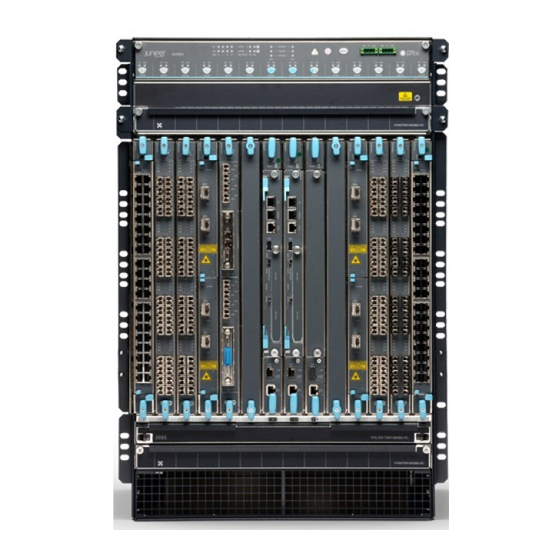
Juniper EX9214 Hardware Manual (372 pages)
EX series
Brand:
Juniper
| Category:
Network Router
| Size: 8.74 MB
Table of Contents
Table of Contents
3
About the Documentation
19
Documentation and Release Notes
19
Supported Platforms
19
Documentation Conventions
19
Table 1: Notice Icons
20
Table 2: Text and Syntax Conventions
20
Documentation Feedback
21
About the Documentation
21
Requesting Technical Support
22
Self-Help Online Tools and Resources
22
Opening a Case with JTAC
22
Overview
25
Switch Overview
25
Chassis Components and Descriptions
25
Cooling System and Airflow
25
Power Supplies
25
Chapter 1 Switch Overview
27
EX9214 Switch Hardware Overview
27
Software
27
Chassis Physical Specifications
27
Figure 1: Front View of an EX9214 Switch
28
Host Subsystem
29
Figure 2: Rear View of an EX9214 Switch with AC Power Supplies
29
Figure 3: Rear View of an EX9214 Switch with DC Power Supplies
29
Switch Overview
29
Line Cards
30
Table 3: Line Cards for EX9214 Switches
30
Cooling System
31
Power Supplies
31
Table 4: Power Supplies Supported on EX9214 Switches
31
EX9214 Switch Configurations
32
Table 5: EX9214 Switch Hardware Configurations
32
EX9214 Switch Hardware and CLI Terminology Mapping
34
Table 6: CLI Equivalents of Terms Used in Documentation for EX9214
34
Chapter 2 Chassis Components and Descriptions
39
Chassis Physical Specifications of an EX9214 Switch
39
Table 7: Physical Specifications of the EX9214 Switch Chassis
39
Figure 4: EX9214 Switch
41
Chassis Components and Descriptions
41
Figure 5: Rear View of an EX9214 Switch with AC Power Supplies
42
Figure 6: Rear View of an EX9214 Switch with DC Power Supplies
42
Field-Replaceable Units in an EX9200 Switch
43
Table 8: Frus in an EX9200 Switch
43
Understanding EX9214 Switch Component and Functionality Redundancy
45
Line Cards
45
Craft Interface in an EX9200 Switch
46
Figure 7: Craft Interface in an EX9204 Switch
46
Figure 8: Craft Interface in an EX9208 Switch
47
Figure 9: Craft Interface in an EX9214 Switch
47
Fan Leds
48
Host Subsystem Leds
48
Table 10: Fan Leds on the Craft Interface
48
Table 9: Host Subsystem Leds on the Craft Interface
48
Line Card Leds and Control Buttons
49
Power Supply (PEM) Leds
49
Switch Fabric Leds and Control Buttons
49
Table 11: Power Supply Leds on the Craft Interface
49
Table 12: Switch Fabric Module Leds on the Craft Interface
49
Alarm Leds and Alarm Cutoff Button
50
Table 13: Line Card Leds on the Craft Interface
50
Table 14: Alarm Leds and Alarm Cutoff/Lamp Test Button
50
Alarm Relay Contacts
51
Midplane in an EX9200 Switch
51
Figure 10: Alarm Relay Contacts in EX9200 Switches
51
Figure 11: Midplane in an EX9204 Switch
52
Figure 12: Midplane in an EX9208 Switch
52
Routing Engine Module in an EX9200 Switch
53
Figure 13: Midplane in an EX9214 Switch
53
Figure 14: EX9200-RE Module in an EX9200 Switch
55
Figure 15: EX9200-RE2 Module in an EX9200 Switch
56
Switch Fabric Module in an EX9200 Switch
57
Table 15: Routing Engine Module Specifications
57
Figure 16: SF Module EX9200-SF
58
Figure 17: SF Module EX9200-SF2
59
Host Subsystem in an EX9200 Switch
60
Network Port Leds on Line Cards in an EX9200 Switch
61
Table 16: Network Port Leds on Line Cards in an EX9200 Switch-Link/Activity
61
Modular Interface Card LED in an EX9200 Switch
62
Led
62
Table 17: Network Port Leds on Line Cards in an EX9200 Switch-Status
62
Routing Engine Module Leds in an EX9200 Switch
63
Table 18: MIC LED for EX9200 Switches
63
Table 19: Leds on the EX9200-RE Routing Engine Module
63
Table 20: Leds on the EX9200-RE2 Routing Engine Module
63
Switch Fabric Module Leds in an EX9200 Switch
64
Cable Management Bracket in an EX9214 Switch
65
Figure 18: Cable Management Bracket
65
Table 21: SF Module Leds of an EX9200 Switch
65
Chapter 3 Cooling System and Airflow
67
Cooling System and Airflow in an EX9214 Switch
67
Fan Tray
67
Figure 19: Fan Tray Used in an EX9214 Switch
67
Figure 20: Air Filter Used in an EX9214 Switch
67
Airflow Direction in the EX9214 Switch Chassis
68
Figure 21: Airflow through the EX9214 Switch Chassis
68
Chapter 4 Power Supplies
69
AC Power Supply in an EX9214 Switch
69
AC Power Supply Description
69
Figure 22: AC Power Supply in an EX9214 Switch
70
AC Power Supply Configurations
71
AC Power Supply Leds in an EX9214 Switch
71
Table 22: AC Power Supply Leds in EX9214 Switches
72
DC Power Supply in an EX9214 Switch
73
DC Power Supply Description
74
Figure 23: DC Power Supply in an EX9214 Switch
74
DC Power Supply Configurations
75
DC Power Supply Leds in an EX9214 Switch
75
Table 23: DC Power Supply Leds in EX9214 Switches
76
Chapter 5 Line Cards
79
Line Card Model and Version Compatibility in an EX9200 Switch
79
Table 24: Line Card Models for EX9200 Switches
80
EX9200-2C-8XS Line Card
81
Line Card Models
82
Line Card Components
82
Figure 24: EX9200-2C-8XS Line Card
82
Table 25: EX9200-2C-8XS Line Card
82
EX9200-4QS Line Card
83
Line Card Models
83
Table 26: EX9200-4QS Line Card
83
Line Card Components
84
EX9200-6QS Line Card
84
Figure 25: EX9200-4QS Line Card
84
Switches
84
Figure 26: EX9200-6QS Line Card
85
Line Card Models
85
Table 27: EX9200-6QS Line Card
85
Line Card Components
86
EX9200-MPC Line Card
86
Line Card Models
87
Figure 27: EX9200-MPC Line Card
87
Table 28: EX9200-MPC
87
Line Card Components
88
Figure 28: EX9200-10XS-MIC
88
Figure 29: EX9200-20F-MIC
89
Figure 30: EX9200-40T-MIC
89
EX9200-12QS Line Card
90
Line Card Models
90
Table 29: EX9200-12QS Line Card
90
Installing a Line Card in an EX9200 Switch
90
Handling and Storing Line Cards in EX9200 Switches
90
This Topic Describes
90
Line Card Components
90
Table
90
Line Card Components
91
Figure 31: EX9200-12QS Line Card
91
EX9200-32XS Line Card
92
Line Card Models
92
Table 30: EX9200-32XS Line Card
92
Through
92
Line Card Components
93
EX9200-40T Line Card
93
Figure 32: EX9200-32XS Line Card
93
Figure 33: EX9200-40T Line Card
94
Line Card Components
94
Line Card Models
94
Table 31: EX9200-40T Line Card
94
EX9200-40F Line Card
95
Line Card Models
95
Figure 34: EX9200-40F Line Card
95
Table 32: EX9200-40F Line Card
95
Line Card Components
96
EX9200-40F-M Line Card
96
Line Card Models
96
Line Card Components
97
Figure 35: EX9200-40F-M Line Card
97
Table 33: EX9200-40F-M Line Card
97
EX9200-40XS Line Card
98
Line Card Models
98
Table 34: EX9200-40XS Line Card
98
Line Card Components
99
Line Card LED in an EX9200 Switch
99
Figure 36: EX9200-40XS Line Card
99
Configuring Rate Selectability at the PIC Level
100
Port Speeds
100
Table 35: LED on Line Cards for EX9200 Switches
100
Configuring Rate Selectability at the Port Level
102
Table 36: Active Physical Ports on EX9200-12QS Line Card Based on the Number-Of-Ports Configuration
102
Line Cards
103
Site Planning, Preparation, and Specifications
105
Chapter 6 Preparation Overview
107
Preparation Overview
107
Site Preparation Checklist for an EX9214 Switch
107
Table 37: Site Preparation Checklist
107
Environmental Requirements and Specifications for EX Series Switches
109
Preparation Overview
109
Table 38: EX Series Switch Environmental Tolerances
109
General Site Guidelines
113
Site Electrical Wiring Guidelines
113
Table 39: Site Electrical Wiring Guidelines
113
Rack Requirements
114
Table 40: Rack Requirements and Specifications
114
Cabinet Requirements
115
Table 41: Cabinet Requirements and Specifications
115
Figure 37: Airflow through an EX9214 Switch
116
Switch
116
Figure 38: Clearance Requirements for Airflow and Hardware Maintenance for an EX9214 Switch with AC Power Supplies
117
Figure 39: Clearance Requirements for Airflow and Hardware Maintenance for an EX9214 Switch with DC Power Supplies
117
Chapter 7 Planning Power Requirements
119
Power Requirements for EX9200 Switch Components
119
Table 42: EX9200 Switch Component Power Requirements
119
AC Power Supply Specifications for EX9214 Switches
120
Table 43: AC Power Supply Specifications for an EX9214 Switch
120
AC Power Cord Specifications for an EX9214 Switch
121
Table 44: AC Power System Specifications
121
Table 45: AC Power Cord Specifications for an EX9214 Switch
121
Figure 40: AC Plug Types
122
DC Power Supply Specifications for EX9214 Switches
123
Table 46: DC Power Supply Specifications for an EX9214 Switch
123
Grounding Cable and Lug Specifications for EX9200 Switches
124
Table 47: DC Power System Specifications
124
Figure 41: Grounding Lug for an EX9200 Switch
125
Grounding Cable Lug Specifications for an EX9200 Switch
125
Grounding Cable Specifications for an EX9200 Switch
125
Grounding Points Specifications for an EX9200 Switch
125
Calculating the EX Series Switch Fiber-Optic Cable Power Budget
126
Table 48: Grounding Cable Specifications
126
Calculating the EX Series Switch Fiber-Optic Cable Power Margin
127
Table 49: Estimated Values for Factors Causing Link Loss
127
Chapter 8 Transceiver and Cable Specifications
129
Pluggable Transceivers Supported on EX9200 Switches
129
Pluggable Transceivers Supported on EX Series Switches
130
SFP+ Direct Attach Copper Cables for EX Series Switches
134
Cable Specifications
135
Figure 42: SFP+ Direct Attach Copper Cables for EX Series Switches
135
Table 50: Software Support for SFP+ Passive Direct Attach Copper Cables for
135
Table 51: SFP+ Direct Attach Copper Cable Specifications
137
Standards Supported by These Cables
140
QSFP+ Direct Attach Copper Cables for EX Series Switches
141
Cable Specifications
141
Figure 43: QSFP+ Direct Attach Copper Cables for EX Series Switches
141
Table 52: Software Support for QSFP+ Passive Direct Attach Copper Cables for
141
Table 53: QSFP+ Direct Attach Copper Cable Specifications
143
Management Cable Specifications
146
Table 54: Specifications of Cables to Connect to Management Devices
146
Understanding EX Series Switches Fiber-Optic Cable Signal Loss, Attenuation
147
And Dispersion
147
Signal Loss in Multimode and Single-Mode Fiber-Optic Cable
147
Attenuation and Dispersion in Fiber-Optic Cable
147
Chapter 9 Pinout Specifications
149
USB Port Specifications for an EX Series Switch
150
RJ-45 Management Port Connector Pinout Information
151
RJ-45 to DB-9 Serial Port Adapter Pinout Information
151
Table 56: RJ-45 Management Port Connector Pinout Information
151
Table 57: RJ-45 to DB-9 Serial Port Adapter Pinout Information
152
Pinout Specifications
149
Console Port Connector Pinout Information
149
Table 55: Console Port Connector Pinout Information
149
Initial Installation and Configuration
153
Chapter 10 Unpacking the Switch
155
Unpacking the EX9200 Switch
155
Unpacking a Line Card Used in an EX9200 Switch
156
Figure 44: Contents of the Shipping Crate for EX9200 Switches
156
Figure 45: Unpacking a Line Card Used in an EX9200 Switch
157
Parts Inventory (Packing List) for an EX9214 Switch
158
Table 58: Parts List for Different EX9214 Switch Configurations
158
Table 59: Accessory Box Parts List
159
Registering Products-Mandatory for Validating Slas
160
Chapter 11 Installing the Switch
161
Installing and Connecting an EX9214 Switch
161
Installing a Mounting Shelf in a Rack or Cabinet for an EX9214 Switch
162
Moving the Mounting Brackets for Center-Mounting an EX9200 Switch
164
Figure 46: Installing the Mounting Shelf on an Open-Frame Rack
164
Mounting an EX9200 Switch on a Rack or Cabinet Using a Mechanical Lift
165
Installing and Removing EX9214 Switch Hardware Components
168
Figure 47: Installing the Switch in an Open-Frame Rack
168
Chapter 12 Connecting the Switch to Power
171
Connecting Earth Ground to an EX Series Switch
171
Parts and Tools Required for Connecting an EX Series Switch to Earth Ground
172
Table 61: Parts and Tools Required for Connecting an EX Series Switch to Earth Ground
172
Special Instructions to Follow before Connecting Earth Ground to a
175
Switch
175
Figure 48: Connecting the Grounding Lug to a Switch Mounted on Four Posts of
175
Table 62: Special Instructions to Follow before Connecting Earth Ground to a
175
Connecting Earth Ground to an EX Series Switch
176
Figure 49: Connecting a Grounding Cable to an EX Series Switch
176
Connecting AC Power to an EX9214 Switch
178
Powering on an AC-Powered EX9200 Switch
180
Figure 50: Connecting AC Power to an EX9214 Switch
180
Connecting DC Power to an EX9214 Switch
182
Powering on a DC-Powered EX9200 Switch
186
Figure 51: Connecting DC Power to an EX9214 Switch
186
Chapter 13 Connecting the Switch to the Network
189
Connecting an EX9200 Switch to a Network for Out-Of-Band Management
189
Connecting an EX9200 Switch to a Management Console or an Auxiliary
189
Device
189
Figure 52: Ethernet Cable Connector
189
Figure 53: Ethernet Management Port on the RE Module in EX9200 Switches
190
Figure 54: Ethernet Cable Connector
190
Connecting the EX9200 Switch to an External Alarm-Reporting Device
191
Figure 55: Console and Auxiliary Ports on the RE Module in EX9200 Switches
191
Figure 56: Alarm Relay Contacts
192
Switch
192
Connecting a Fiber-Optic Cable
193
Figure 57: Alarm Relay Contacts
193
Figure 58: Connecting a Fiber-Optic Cable to an Optical Transceiver Installed
194
Chapter 14 Performing Initial Configuration
195
EX9200 Switch Default Configuration
195
Connecting and Configuring an EX9200 Switch (CLI Procedure)
196
Installing, Maintaining, and Replacing Components
201
Chapter 15 Removing the Switch
203
Removing an EX9200 Switch from a Rack or Cabinet Using a Mechanical Lift
204
Removing the Switch
203
Powering off an EX9200 Switch
203
Chapter 16 Replacing Cooling System Component
207
Figure 59: Installing a Fan Tray in an EX9208 Switch
208
Figure 60: Installing the Upper Fan Tray in an EX9214 Switch
209
Removing a Fan Tray from an EX9200 Switch
210
Figure 61: Removing a Fan Tray from an EX9200 Switch
211
Figure 62: Removing the Upper Fan Tray in an EX9214 Switch
212
Replacing Cooling System Component
207
Installing a Fan Tray in an EX9200 Switch
207
Chapter 17 Replacing Power Supply
213
Installing an AC Power Supply in an EX9214 Switch
213
Figure 63: Installing an AC Power Supply in an EX9214 Switch
214
Removing an AC Power Supply from an EX9214 Switch
215
Installing a DC Power Supply in an EX9214 Switch
217
Figure 64: Removing an AC Power Supply from an EX9214 Switch
217
Figure 65: Installing a DC Power Supply in an EX9214 Switch
219
Removing a DC Power Supply from an EX9214 Switch
220
Figure 66: Removing a DC Power Supply from an EX9214 Switch
222
Chapter 18 Replacing Routing Engine (RE) Module
223
Installing an RE Module in an EX9200 Switch
223
Removing an RE Module from an EX9200 Switch
225
Figure 67: Installing an RE Module in an EX9200 Switch
225
Taking the Host Subsystem Offline in an EX9200 Switch
227
Figure 68: Removing an RE Module from an EX9200 Switch
227
Chapter 19 Upgrading and Replacing Switch Fabric (SF) Module
229
Upgrading an EX9200-SF to an EX9200-SF2
229
Preparing the EX9200 Switch for an EX9200-SF2 Upgrade
229
Powering off the Switch
230
Removing a Routing Engine from an EX9200-SF Module
230
Replacing the EX9200-SF with the EX9200-SF2
230
Installing a Routing Engine into an EX9200-SF2
231
Powering on the Switch
231
Completing the EX9200-SF2 Upgrade
232
Installing an SF Module in an EX9200 Switch
233
Figure 69: Installing an SF Module in an EX9200 Switch
235
Removing an SF Module from an EX9200 Switch
236
Figure 70: Removing an SF Module from an EX9200 Switch
237
Chapter 20 Maintaining and Replacing Line Card
239
Handling and Storing Line Cards in EX9200 Switches
239
Figure 71: Edges of the Line Cards
239
Holding a Line Card
240
Figure 72: Do Not Grasp the Connector Edge
241
Figure 73: Do Not Rest the Edge of a Line Card on a Hard Surface
241
Storing a Line Card
242
Maintaining Line Card Cables in EX9200 Switches
242
Unpacking a Line Card Used in an EX9200 Switch
243
Installing a Line Card in an EX9200 Switch
244
Figure 74: Unpacking a Line Card Used in an EX9200 Switch
244
Removing a Line Card from an EX9200 Switch
246
Figure 75: Installing a Line Card
246
Figure 76: Removing a Line Card from an EX9200 Switch
248
Chapter 21 Replacing a MIC in an EX9200-MPC Line Card
249
Installing a MIC in an EX9200-MPC Line Card
249
Figure 77: Installing the Septum
251
Figure 78: Removing the Septum
251
Figure 79: Installing an EX9200-10XS-MIC or EX9200-20F-MIC
253
Removing a MIC from an EX9200-MPC Line Card
254
Figure 80: Installing an EX9200-40T-MIC
254
Figure 81: Removing an EX9200-10XS-MIC or EX9200-20F-MIC
257
Figure 82: Removing an EX9200-40T-MIC
258
Chapter 22 Replacing Transceiver
259
Removing a Transceiver
261
Figure 83: Installing a Transceiver
261
Figure 84: Removing an SFP, SFP+, XFP, or a QSFP+ Transceiver
263
Replacing Transceiver
259
Installing a Transceiver
259
Chapter 23 Replacing Alarm Relay Wire
265
Switch
265
Switch
266
Figure 85: Alarm Relay Contacts
266
Figure 86: Alarm Relay Contacts
266
Chapter 24 Maintaining and Replacing Fiber-Optic Cable
267
Connecting a Fiber-Optic Cable
267
Disconnecting a Fiber-Optic Cable from a Device
268
Figure 87: Connecting a Fiber-Optic Cable to an Optical Transceiver Installed in
268
Maintaining Fiber-Optic Cables
269
Chapter 25 Replacing Cable Management Bracket
271
Installing the Cable Management Bracket in an EX9214 Switch
271
Removing the Cable Management Bracket from an EX9214 Switch
272
Figure 88: Installing the Cable Management Bracket in an EX9214 Switch
272
Figure 89: Removing the Cable Management Bracket
273
Chapter 26 Routine Maintenance
275
Routine Maintenance Procedures for EX9200 Switches
275
Handling and Storing Line Cards in EX9200 Switches
275
Figure 90: Edges of the Line Cards
275
Holding a Line Card
276
Figure 91: Do Not Grasp the Connector Edge
277
Figure 92: Do Not Rest the Edge of a Line Card on a Hard Surface
278
Storing a Line Card
278
Maintaining Line Card Cables in EX9200 Switches
279
Maintaining Power Supplies in EX9200 Switches
279
Maintaining the Air Filter in EX9200 Switches
280
Maintaining Host Subsystem in EX9200 Switches
281
Maintaining the Fan Tray in EX9200 Switches
284
Chapter 27 Contactingcustomersupportandreturningthechassisor
287
Components
287
Returning an EX9200 Switch or Component for Repair or Replacement
287
Locating the Serial Number on an EX9214 Switch or Component
288
Listing the Switch and Components Details with the CLI
288
Locating the Serial Number ID Label on an EX9214 Switch Chassis
290
Locating Serial Number ID Labels on FRU Components
291
Figure 93: Location of the Serial Number ID Label on EX9214 Switch Chassis
291
Figure 94: Location of the Serial Number ID Label on an AC Power Supply
292
Figure 95: Location of the Serial Number ID Label on a DC Power Supply
292
Figure 96: Location of the Serial Number ID Label on the SF Module
293
Figure 97: Location of the Serial Number ID Label on the RE Module
293
Contacting Customer Support to Obtain Return Material Authorization
294
Figure 98: Location of the Serial Number ID Label on the Fan Tray
294
Packing an EX9200 Switch or Component
295
Packing an EX9200 Switch
295
Packing EX9200 Switch Components for Shipping
297
Troubleshooting
299
Chapter 28 Troubleshooting Procedures
301
Troubleshooting the Cooling System in an EX9200 Switch
301
Troubleshooting Power Supplies in an EX9200 Switch
302
Troubleshooting Line Cards in EX9200 Switches
303
Troubleshooting Traffic Drops on EX9200-6QS Line Cards
305
Chapter 29 Alarms and System Log Messages
307
Understanding Alarm Types and Severity Levels on EX Series Switches
307
Table 63: Alarm Terms
307
Chassis Component Alarm Conditions on EX9200 Switches
308
Table 64: Chassis Component Alarm Conditions on EX9200 Switches
308
Backup Routing Engine Alarms
314
Table 65: Backup Routing Engine Alarms
315
Monitoring System Log Messages
316
Table 66: Filtering System Log Messages
316
Table 67: Viewing System Log Messages
319
Safety and Compliance Information
321
Chapter 30 Generalsafetyguidelinesandwarnings
323
General Safety Guidelines and Warnings
323
Definitions of Safety Warning Levels
324
Qualified Personnel Warning
326
Warning Statement for Norway and Sweden
327
Chapter 31 Fire Safety Requirements
329
Chapter 32 Installation Safety Guidelines and Warnings
331
Installation Instructions Warning
331
Chassis Lifting Guidelines
332
Restricted Access Warning
332
Ramp Warning
334
Rack-Mounting and Cabinet-Mounting Warnings
334
Grounded Equipment Warning
338
Chapter 33 Radiation and Laser Safety Guidelines and Warnings
341
Radiation from Open Port Apertures Warning
341
Laser and LED Safety Guidelines and Warnings
342
General Laser Safety Guidelines
342
Class 1 Laser Product Warning
343
Class 1 LED Product Warning
343
Laser Beam Warning
343
Chapter 34 Maintenance and Operational Safety Warnings
345
Maintenance and Operational Safety Guidelines and Warnings
345
Battery Handling Warning
345
Jewelry Removal Warning
346
Lightning Activity Warning
347
Operating Temperature Warning
348
Product Disposal Warning
349
Chapter 35 Electrical Safety Guidelines and Warnings
351
General Electrical Safety Guidelines and Warnings
351
Action to Take after an Electrical Accident
352
Prevention of Electrostatic Discharge Damage
353
AC Power Electrical Safety Guidelines
354
Figure 99: Placing a Component into an Antistatic Bag
354
AC Power Disconnection Warning
355
DC Power Electrical Safety Guidelines for Switches
356
DC Power Disconnection Warning
359
DC Power Grounding Requirements and Warning
360
DC Power Wiring Sequence Warning
361
DC Power Wiring Terminations Warning
363
Multiple Power Supplies Disconnection Warning
364
TN Power Warning
364
Chapter 36 Agency Approvals and Compliance Statements
367
Agency Approvals for EX Series Switches
367
Battery Compliance Statement for Environmental Requirements for EX Series
367
Switches
367
Compliance Statements for EMC Requirements for EX Series Switches
368
Canada
369
European Community
369
Israel
369
Japan
370
Korea
370
United States
370
FCC Part 15 Statement
370
Compliance Statements for Acoustic Noise for Ex Series Switches
372
Advertisement
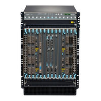
Juniper EX9214 Hardware Manual (385 pages)
Brand:
Juniper
| Category:
Switch
| Size: 5.79 MB
Table of Contents
Table of Contents
3
About this Guide
11
Overview
12
EX9214 System Overview
13
EX9214 Switch Hardware Overview
13
EX9214 Switch Configurations
20
EX9214 Switch Hardware and CLI Terminology Mapping
25
Chassis Physical Specifications of an EX9214 Switch
31
Field-Replaceable Units in an EX9200 Switch
36
EX9214 Chassis
38
Understanding EX9214 Switch Component and Functionality Redundancy
39
Craft Interface in an EX9200 Switch
40
Host Subsystem Leds
41
Fan Leds
41
Power Supply (PEM) Leds
41
Switch Fabric Leds and Control Buttons
41
Line Card Leds and Control Buttons
41
Alarm Leds and Alarm Cutoff Button
45
Alarm Relay Contacts
46
Midplane in an EX9200 Switch
47
Cable Management Bracket in an EX9214 Switch
50
EX9214 Cooling System
51
EX9214 Power System
54
AC Power Supply in an EX9214 Switch
54
AC Power Cord Specifications for an EX9214 Switch
57
AC Power Supply Specifications for EX9214 Switches
59
AC Power Supply Leds in an EX9214 Switch
60
DC Power Supply in an EX9214 Switch
63
DC Power Supply Specifications for EX9214 Switches
65
DC Power Supply Leds in an EX9214 Switch
66
Power Requirements for EX9200 Switch Components
68
EX9200 Host Subsystem
70
Host Subsystem in an EX9200 Switch
71
Routing Engine Module in an EX9200 Switch
71
Routing Engine Module Leds in an EX9200 Switch
76
Switch Fabric Module in an EX9200 Switch
78
Switch Fabric Module Leds in an EX9200 Switch
82
EX9200-SF3 Module in an EX9200 Switch
82
EX9200 Line Cards
91
Line Card Model and Version Compatibility in an EX9200 Switch
92
EX9200-2C-8XS Line Card
95
EX9200-4QS Line Card
97
EX9200-6QS Line Card
98
EX9200-MPC Line Card
101
EX9200-12QS Line Card
105
EX9200-15C Line Card
107
EX9200-32XS Line Card
111
EX9200-40T Line Card
112
EX9200-40F Line Card
114
EX9200-40F-M Line Card
116
EX9200-40XS Line Card
118
Line Card LED in an EX9200 Switch
120
Network Port Leds on Line Cards in an EX9200 Switch
120
Modular Interface Card LED in an EX9200 Switch
122
Configuring Rate Selectability on an EX9200-12QS Line Card to Enable Different Port Speeds
123
Configuring Rate Selectability at the PIC Level
123
Configuring Rate Selectability at the Port Level
125
Site Planning, Preparation, and Specifications
128
Site Preparation Checklist for an EX9214 Switch
129
EX9214 Site Guidelines and Requirements
131
Environmental Requirements and Specifications for EX Series Switches
131
General Site Guidelines
138
Site Electrical Wiring Guidelines
138
Clearance Requirements for Airflow and Hardware Maintenance for an EX9214 Switch
139
Rack Requirements
143
Cabinet Requirements
144
Grounding Cable and Lug Specifications for EX9200 Switches
145
EX9200 Network Cable and Transceiver Planning
148
Pluggable Transceivers Supported on EX9200 Switches
148
Overview of EX Series Switches: Fiber-Optic Cable Signal Loss, Attenuation, and Dispersion
149
Calculate the Fiber-Optic Cable Power Budget for EX Series Devices
151
Calculating the Fiber-Optic Cable Power Margin for EX Series Devices
151
EX9200 Management Cable Specifications and Pinouts
153
Management Cable Specifications
153
Console Port Connector Pinout Information
154
USB Port Specifications for an EX Series Switch
155
RJ-45 Management Port Connector Pinout Information
156
RJ-45 to DB-9 Serial Port Adapter Pinout Information
157
Initial Installation and Configuration
158
Unpacking and Mounting the EX9214 Switch
159
Unpacking the EX9200 Switch
159
Unpacking a Line Card Used in an EX9200 Switch
160
Parts Inventory (Packing List) for an EX9214 Switch
161
Register Products-Mandatory to Validate Slas
164
Installing and Connecting an EX9214 Switch
165
Installing a Mounting Shelf in a Rack or Cabinet for an EX9214 Switch
166
Moving the Mounting Brackets for Center-Mounting an EX9200 Switch
169
Mounting an EX9200 Switch on a Rack or Cabinet Using a Mechanical Lift
171
Ensure that You Have the Following Parts and Tools Available
172
Phillips (+) Screwdrivers, Number 1 and
172
Connecting the EX9214 to Power
175
Connect Earth Ground to an EX Series Switch
175
Connecting AC Power to an EX9214 Switch
185
Powering on an AC-Powered EX9200 Switch
188
Connecting DC Power to an EX9214 Switch
190
Powering on a DC-Powered EX9200 Switch
195
Connecting the EX9200 to External Devices
197
Connecting an EX9200 Switch to a Network for Out-Of-Band Management
198
Connecting an EX9200 Switch to a Management Console or an Auxiliary Device
199
Connecting the EX9200 Switch to an External Alarm-Reporting Device
200
Connecting the EX9200 to the Network
201
Install a Transceiver
201
Connect a Fiber-Optic Cable
204
Configuring Junos os on the EX9200
205
EX9200 Switch Default Configuration
205
Connecting and Configuring an EX9200 Switch (CLI Procedure)
206
Maintaining Components
212
Routine Maintenance Procedures for EX9200 Switches
213
Maintaining the EX9200 Cooling System
213
Removing a Fan Tray from an EX9200 Switch
214
Installing a Fan Tray in an EX9200 Switch
216
Maintaining the Fan Tray in EX9200 Switches
220
Maintaining the Air Filter in EX9200 Switches
222
Maintaining the EX9214 Power System
223
Removing an AC Power Supply from an EX9214 Switch
224
Installing an AC Power Supply in an EX9214 Switch
227
Removing a DC Power Supply from an EX9214 Switch
229
Installing a DC Power Supply in an EX9214 Switch
232
Maintaining Power Supplies in EX9200 Switches
234
Maintaining the EX9200 Host Subsystem
235
Taking the Host Subsystem Offline in an EX9200 Switch
236
Removing an RE Module from an EX9200 Switch
237
Installing an RE Module in an EX9200 Switch
238
Upgrading an EX9200-SF to an EX9200-SF2
240
Preparing the EX9200 Switch for an EX9200-SF2 Upgrade
241
Powering off the Switch
241
Removing a Routing Engine from an EX9200-SF Module
241
Replacing the EX9200-SF with the EX9200-SF2
242
Installing a Routing Engine into an EX9200-SF2
242
Powering on the Switch
242
Completing the EX9200-SF2 Upgrade
242
Upgrading to an EX9200-SF3
244
Preparing the EX9200 Switch for an EX9200-SF3 Upgrade
245
Powering off the Switch
245
Removing a Routing Engine from an SF Module
245
Replacing the EX9200-SF or EX9200-SF2 with the EX9200-SF3
245
Installing a Routing Engine into an EX9200-SF3
246
Powering on the Switch
246
Completing the EX9200-SF3 Upgrade
246
Removing an SF Module from an EX9200 Switch
247
Installing an SF Module in an EX9200 Switch
249
Maintaining the Host Subsystem in EX9200 Switches
253
Maintaining the EX9200 Line Cards
257
Handling and Storing Line Cards
257
Holding a Line Card
258
Storing a Line Card
260
Maintaining Line Card Cables
261
Unpacking a Line Card Used in an EX9200 Switch
261
Removing a Line Card from an EX9200 Switch
262
Installing a Line Card in an EX9200 Switch
265
Removing a MIC from an EX9200-MPC Line Card
267
Installing a MIC in an EX9200-MPC Line Card
271
Maintain Transceivers
276
Remove a Transceiver
277
Install a Transceiver
279
Maintaining Alarm Relay Wire
282
Disconnecting the Alarm Relay Wires from the Craft Interface in an EX9200 Switch
283
Connecting the Alarm Relay Wires to the Craft Interface in an EX9200 Switch
283
Maintain Fiber-Optic Cables
285
Connect a Fiber-Optic Cable
285
Disconnect a Fiber-Optic Cable
286
How to Handle Fiber-Optic Cables
287
Removing an EX9214 from a Rack or Cabinet
288
Powering off an EX9200 Switch
288
Removing an EX9200 Switch from a Rack or Cabinet Using a Mechanical Lift
289
Maintaining the EX9214 Cable Management Bracket
290
Removing the Cable Management Bracket from an EX9214 Switch
290
Installing the Cable Management Bracket in an EX9214 Switch
292
Troubleshooting Hardware
294
Troubleshooting EX9200 Components
295
Troubleshooting the Cooling System in an EX9200 Switch
295
Troubleshooting Power Supplies in an EX9200 Switch
296
Troubleshooting Line Cards in EX9200 Switches
298
Troubleshooting Traffic Drops on EX9200-6QS Line Cards
301
Understand Alarm Types and Severity Levels on EX Series Switches
302
Chassis Component Alarm Conditions on EX9200 Switches
304
Monitor System Log Messages
312
Troubleshoot Temperature Alarms in EX Series Switches
319
Contacting Customer Support and Returning the Chassis or Components
326
Returning an EX9214 Chassis or Components
327
Returning an EX9200 Switch or Component for Repair or Replacement
327
Locating the Serial Number on an EX9214 Switch or Component
328
Listing the Switch and Components Details with the CLI
328
Locating the Serial Number ID Label on an EX9214 Switch Chassis
332
Locating Serial Number ID Labels on FRU Components
332
Contact Customer Support to Obtain a Return Material Authorization
337
Packing an EX9200 Switch or Component
338
Packing an EX9200 Switch
338
Packing EX9200 Switch Components for Shipping
339
Safety and Compliance Information
341
General Safety Guidelines and Warnings
343
Definitions of Safety Warning Levels
344
Qualified Personnel Warning
346
Warning Statement for Norway and Sweden
346
Fire Safety Requirements
347
Installation Instructions Warning
348
Chassis and Component Lifting Guidelines
349
Restricted Access Warning
349
Ramp Warning
351
Rack-Mounting and Cabinet-Mounting Warnings
351
Grounded Equipment Warning
355
Radiation from Open Port Apertures Warning
356
Laser and LED Safety Guidelines and Warnings
357
Maintenance and Operational Safety Guidelines and Warnings
360
General Electrical Safety Guidelines and Warnings
366
Action to Take after an Electrical Accident
367
Prevention of Electrostatic Discharge Damage
368
AC Power Electrical Safety Guidelines
369
AC Power Disconnection Warning
370
DC Power Electrical Safety Guidelines
371
DC Power Disconnection Warning
372
DC Power Grounding Requirements and Warning
374
DC Power Wiring Sequence Warning
374
DC Power Wiring Terminations Warning
376
Multiple Power Supplies Disconnection Warning
377
TN Power Warning
378
Agency Approvals for EX Series Switches
379
Battery Compliance Statement for Environmental Requirements for EX Series Switches
380
Compliance Statements for EMC Requirements for EX Series Switches
381
Compliance Statements for Acoustic Noise for EX Series Switches
385
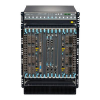
Juniper EX9214 Quick Start Manual (13 pages)
Brand:
Juniper
| Category:
Switch
| Size: 0.67 MB
Table of Contents
Step 2: up and Running
9
Set Parameter Values
9
Perform the Initial Configuration
10
Safety Warnings Summary
12
Power Cable Warning (Japanese)
13
Contacting Juniper Networks
13
Advertisement
Advertisement
Related Products
Juniper EX9200 Series
Juniper EX9208
Juniper EX9251
Juniper EX9253
Juniper EX9204
Juniper EX 4200 24F
Juniper EX2300-C-12P
Juniper EX2300-48P
Juniper EX2300-24T-VC
Juniper EX2300-24P-VC
Juniper Categories
Network Router
Switch
Gateway
Software
Network Hardware
More Juniper Manuals
Login
Sign In
OR
Sign in with Facebook
Sign in with Google
Upload manual
Upload from disk
Upload from URL