Sign In
Upload
Manuals
Brands
Juniper Manuals
Network Router
ACX2100
Juniper ACX2100 Manuals
Manuals and User Guides for Juniper ACX2100. We have
6
Juniper ACX2100 manuals available for free PDF download: Configuration Manual, Hardware Manual, Quick Start Manual
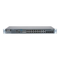
Juniper ACX2100 Configuration Manual (3270 pages)
Junos OS; ACX Series Universal Access Router
Brand:
Juniper
| Category:
Network Router
| Size: 27.72 MB
Table of Contents
Table of Contents
3
List of Tables
45
About the Documentation
53
Documentation and Release Notes
53
Supported Platforms
53
Using the Examples in this Manual
53
Merging a Full Example
54
Merging a Snippet
54
Documentation Conventions
55
Documentation Feedback
57
Requesting Technical Support
57
Self-Help Online Tools and Resources
57
Opening a Case with JTAC
58
Overview
59
Chapter 1 ACX Series Universal Access Router Overview
61
ACX Series Router Architecture
62
Junos os
62
Interfaces
62
Mobile Backhaul
62
Junos Space
63
Protocols and Applications Supported by ACX Series Routers
63
Hardware Architecture Overview
79
Hardware Overview (ACX Series, M Series, MX Series, T Series, and TX Matrix Routers)
80
System Memory
81
Storage Media
82
ACX500 Routers Hardware and CLI Terminology Mapping
83
ACX500 Indoor Routers Hardware and CLI Terminology Mapping
83
ACX500 Outdoor Routers Hardware and CLI Terminology Mapping
85
Mapping
86
ACX1000 and ACX1100 Routers Hardware and CLI Terminology Mapping
88
Mapping
88
ACX1100 Routers Hardware and CLI Terminology Mapping
89
ACX2000 and ACX2100 Routers Hardware and CLI Terminology Mapping
91
ACX2000 Hardware and CLI Terminology Mapping
91
Figure 8: ACX2000 Interface Port Mapping
92
ACX2100 Hardware and CLI Terminology Mapping
93
ACX2200 Routers Hardware and CLI Terminology Mapping
94
ACX4000 Routers Hardware and CLI Terminology Mapping
95
ACX5000 Routers Hardware and CLI Terminology Mapping
97
ACX5048 Router Hardware and CLI Terminology Mapping
97
ACX5096 Router Hardware and CLI Terminology Mapping
98
Figure 13: ACX5096 Interface Port Mapping
99
Part 2 Installing and Upgrading ACX Series Routers
101
Chapter 2 Installing and Upgrading Junos os
103
Installing and Upgrading Junos os
103
Routing Engines and Storage Media Names (ACX Series, M Series, MX Series, PTX Series, T Series, TX Matrix, TX Matrix Plus, and JCS 1200 Routers)
103
Boot Sequence on ACX Series Routers
106
Dual-Root Partitioning ACX Series Routers Overview
106
Boot Media and Boot Partition on the ACX Series Routers
106
Important Features of the Dual-Root Partitioning Scheme
107
Understanding How the Primary Junos os Image with Dual-Root Partitioning Recovers on the ACX Series Router
107
Junos os Release 12.2 or Later Upgrades with Dual-Root Partitioning on ACX Series Routers
109
Installing Junos os Upgrades from a Remote Server on ACX Series Routers
110
Installing Junos os Using a USB Storage Device on ACX Series Routers
110
Example: Installing Junos os and Configuring a Dual-Root Partition on ACX Series Routers Using the CLI
111
Upgrading Software Packages
115
Loading and Committing the Configuration File
118
Checking the Current Configuration and Candidate Software Compatibility
119
Unattended Boot Mode in ACX Series
119
Understanding System Snapshot on an ACX Series Router
122
Example: Taking a Snapshot of the Software and Configuration
123
Routers
126
In-Service Software Upgrade Process
127
Routers
127
Preparing the Router for Software Installation
127
Upgrading the Software Using ISSU
129
Verifying a Unified ISSU
131
Chapter 3 Configuring Autoinstallation
133
Supported Autoinstallation Interfaces and Protocols
134
Typical Autoinstallation Process on a New Router
134
Before You Begin Autoinstallation on an ACX Series Universal Access Router
135
Autoinstallation Configuration of ACX Series Universal Access Routers
136
Verifying Autoinstallation on ACX Series Universal Access Routers
137
USB Autoinstallation on ACX Series Routers
138
Autoinstallation on ACX Series Routers in Hybrid Mode Overview
139
Prerequisites for Autoinstallation on ACX Series Routers in Hybrid Mode
141
Autoinstallation Process on a New ACX Series Router in Hybrid Mode
142
Configuring Autoinstallation of ACX Series Routers in Hybrid Mode
145
Part 3 Configuring Interfaces and Chassis on ACX Series Routers
149
Configuring Autoinstallation
133
ACX Series Autoinstallation Overview
133
Chapter 4 Configuring Interfaces and Chassis
151
Understanding Interfaces on ACX Series Universal Access Routers
152
T1 and E1 Time-Division Multiplexing (TDM) Interfaces
153
Inverse Multiplexing for ATM (IMA)
153
Gigabit Ethernet Interfaces
153
Configuring the Media MTU on ACX Series Routers
155
Media MTU Overview
155
How to Configure the Media MTU
156
Encapsulation Overhead by Encapsulation Type
156
Media MTU Sizes by Interface Type for ACX Series Routers
157
Understanding the Loopback Interface
158
Configuring the Loopback Interface
159
Example: Configuring Two Addresses on the Loopback Interface with Host
159
Routes
160
Routes
161
Example: Configuring Two Addresses on the Loopback Interface with Subnetwork Routes
161
Example: Configuring an Ipv4 and an Ipv6 Address on the Loopback Interface with Subnetwork Routes
161
Understanding Encapsulation on an Interface
162
Gigabit Ethernet Autonegotiation Overview
162
BERT Support on CT1 and CE1 Interfaces
163
Channelized OC3/STM1 (Multi-Rate) Circuit Emulation MIC with SFP
164
Overview
164
16-Port Channelized E1/T1 Circuit Emulation MIC Overview
164
Synchronous Ethernet Overview on the ACX Series Universal Access Routers
165
TDM Cesopsn Overview
166
Configuring TDM Cesopsn on ACX Series Routers Overview
166
Channelization up to the DS0 Level
167
Protocol Support
167
Packet Latency
167
Cesopsn Encapsulation
167
Cesopsn Options
168
Show Commands
168
Cesopsn Pseudowires
168
Satop Emulation on T1 and E1 Interfaces Overview
168
Ethernet Ring Protection Switching Overview
169
Understanding Ethernet Ring Protection Switching Functionality
170
Acronyms
171
Ring Nodes
171
Ring Node States
171
Default Logging of Basic State Transitions on EX Series Switches
172
Failure Detection
172
Logical Ring
172
FDB Flush
172
Traffic Blocking and Forwarding
173
RPL Neighbor Node
173
RAPS Message Blocking and Forwarding
173
Dedicated Signaling Control Channel
174
RAPS Message Termination
174
Revertive and Non-Revertive Modes
175
Multiple Rings
175
Node ID
175
Ring ID
175
Bridge Domains with the Ring Port (MX Series Routers Only)
175
Wait-To-Block Timer
175
Adding and Removing a Node
176
Configuring Ethernet Ring Protection Switching
176
Routers
177
Figure 17: Example of a Three-Node Ring Topology
178
Example: Viewing Ethernet Ring Protection Status-Normal Ring Operation
185
Example: Viewing Ethernet Ring Protection Status-Ring Failure Condition
187
Guidelines for Ethernet Ring Protection Switching on ACX Series Routers
189
Dual-Rate SFP+ Optic Modules for ACX Series Routers
192
Dual Rate SFP+ Capabilities
193
Tri-Rate SFP for ACX5000 Series Routers
193
Configuring Logical Tunnel Interfaces
194
Connecting Logical Systems
194
Guidelines for Configuring Logical Tunnels on ACX Series Routers
195
Configuring an Interface in the VRF Domain to Receive Multicast Traffic
198
Configuring a Proxy Logical Interface in the Global Domain
198
Associating the Proxy Logical Interface to a Logical Interface in a VRF Domain
199
Limitations
199
Understanding Poe on ACX Series Universal Access Routers
200
ACX2000 Poe Specifications
200
Poe Classes and Power Ratings
201
Poe Options
201
Example: Configuring Poe on ACX2000 Routers
202
Example: Disabling a Poe Interface on ACX2000 Routers
207
Configuring a Service Package to be Used in Conjunction with PTP
208
Checklist for Monitoring Fast Ethernet and Gigabit Ethernet Interfaces
208
Checklist for Monitoring T1 Interfaces
209
Understanding Ethernet Link Aggregation on ACX Series Routers
210
Load Balancing
212
LACP Monitoring
213
Link Protection
214
Configuring Link Protection for Aggregated Ethernet Interfaces
214
Disabling Link Protection for Aggregated Ethernet Interfaces
214
Understanding the Algorithm Used to Hash LAG Bundle
214
User-Defined Alarm Relay Overview
216
Alarm Contact Port
216
Alarm Input
216
Alarm Output
217
Configuring Chassis Alarm Relays
217
Configuring Chassis Alarm Input
218
Configuring Chassis Alarm Output
219
Chassis Definitions for Router Model MIB for ACX Series Routers
220
Chapter 5 Configuring E1 and T1 Interfaces
223
Configuring E1 BERT Properties
223
Configuring E1 Loopback Capability
225
Configuring T1 BERT Properties
226
Configuring T1 Loopback Capability
228
Chapter 6 Configuring ATM Interfaces
231
ATM Pseudowire Overview
231
Understanding ATM IMA Configuration on ACX Series Router
232
IMA Version
233
IMA Frame Length
233
Transmit Clock
233
IMA Group Symmetry
233
Minimum Active Links
234
State Transition Variables: Alpha, Beta, and Gamma
234
IMA Link Addition and Deletion
234
IMA Test Pattern Procedure
235
IMA Group Alarms and Group Defects
235
IMA Link Alarms and Link Defects
236
IMA Group Statistics
237
IMA Link Statistics
238
IMA Clocking
239
Differential Delay
239
Configuring ATM IMA on ACX Series
239
Creating an IMA Group (ATM Interfaces)
239
Configuring Group ID for an IMA Link on a T1 Interface or an E1 Interface
240
Configuring ATM Encapsulation Options
240
Configuring IMA Group Options
241
Inverse Multiplexing for ATM (IMA) Overview
242
Configuring Inverse Multiplexing for ATM (IMA)
243
ATM OAM F4 and F5 Cells on ACX Series Routers
243
Defining the ATM OAM F5 Loopback Cell Period
245
Configuring the ATM OAM F5 Loopback Cell Threshold
246
Configuring the Timeout for Bundling of Layer 2 Circuit Cell-Relay Cells
246
Configuring the Layer 2 Circuit Cell-Relay Cell Maximum Overview
247
Class-Based Cell Bundling
247
Chapter 7 Configuring Satop Support on Interfaces
249
Configuring Satop Emulation on Channelized T1 and E1 Interfaces
249
Setting the T1/E1 Emulation Mode
250
Configuring One Full T1 or E1 Interface on Channelized T1 and E1 Interfaces
251
Setting the Satop Encapsulation Mode
253
Configure the Layer 2 Circuit
254
Configuring Satop Emulation on T1/E1 Interfaces on 12-Port Channelized T1/E1 Circuit Emulation Pics
254
Setting the Emulation Mode
255
Configuring Satop Emulation on T1/E1 Interfaces
255
Setting the Encapsulation Mode
255
Configuring Loopback for a T1 Interface or an E1 Interface
256
Setting the Satop Options
256
Configuring the Pseudowire Interface
257
Configuring Satop on 16-Port Channelized E1/T1 Circuit Emulation MIC
259
Configuring T1/E1 Framing Mode at the MIC Level
259
Configuring CT1 Ports down to T1 Channels
260
Configuring CT1 Ports down to DS Channels
260
Chapter 8 Configuring Cesopsn Support on Interfaces
263
Configuring Cesopsn Encapsulation on DS Interfaces
263
Configuring Cesopsn on Channelized OC3/STM1 (Multi-Rate) Circuit Emulation
264
MIC with SFP
264
Configuring SONET/SDH Rate-Selectability
264
Configuring SONET/SDH Framing Mode at the MIC Level
265
Configuring Cesopsn Encapsulation on DS Interfaces on CT1 Channels
266
Configuring COC3 Ports down to CT1 Channels
266
Configuring CT1 Channels down to DS Interfaces
267
Configuring Cesopsn on DS Interfaces
268
Configuring Cesopsn Encapsulation on DS Interfaces on CE1 Channels
269
Configuring CSTM1 Ports down to CE1 Channels
269
Configuring CSTM4 Ports down to CE1 Channels
270
Configuring CE1 Channels down to DS Interfaces
271
Configuring Cesopsn on DS Interfaces
272
Configuring Cesopsn Encapsulation on DS Interfaces
273
Setting the Encapsulation Mode
273
Setting the Cesopsn Options
274
Configuring the Pseudowire Interface
275
Configuring CE1 Channels down to DS Interfaces
276
Configuring Cesopsn on Channelized E1/T1 Circuit Emulation MIC
278
Configuring T1/E1 Framing Mode at the MIC Level
278
Configuring CT1 Interface down to DS Channels
279
Configuring Cesopsn on DS Interfaces
280
Chapter 9 Configuring Timing and Synchronization
281
Automatic Clock Selection Overview
282
Clock Source Selection Algorithm
282
Clock Selection and Quality Level
282
Selection Mode for the Incoming ESMC Quality
283
Clock Sources
283
External Clock Synchronization Overview for ACX Series Routers
284
Automatic Clock Selection
284
Clock Source Selection Algorithm
285
Configuring External Clock Synchronization for ACX Series Routers
286
IEEE 1588V2 PTP Boundary Clock Overview
292
IEEE 1588V2 PTP Boundary Clock
292
Figure 21: Boundary Clocks in a Network
293
Clock Clients
294
IEEE 1588V2 Precision Timing Protocol (PTP)
295
PTP over Ethernet on ACX Series Routers Overview
296
Guidelines for Configuring PTP over Ethernet
298
Configuring Precision Time Protocol Clocking
301
Configuring a PTP Master Boundary Clock
302
Configuring the PTP Master Boundary Clock Parameters
303
Configuring a PTP Master Boundary Clock Interface
304
Example: Configuring a PTP Boundary Clock
306
Example: Configuring a PTP Boundary Clock with Unicast Negotiation
308
Configuring a PTP Slave Clock
312
Configuring the PTP Slave Clock Parameters
313
Configuring the PTP Slave Clock Interface
315
Example: Configuring an Ordinary Slave Clock with Unicast-Negotiation
315
Example: Configuring an Ordinary Slave Clock Without Unicast-Negotiation
319
Configuring Precision Time Protocol over Integrated Routing and Bridging
322
Understanding Transparent Clocks in Precision Time Protocol
325
Configuring Transparent Clock Mode for Precision Time Protocol
327
Configuring a PTP Transparent Clock
328
Configuring PHY Timestamping
328
Enabling PHY Timestamping for Ordinary Clock Slave
329
Enabling PHY Timestamping for Boundary Clock
330
Enabling PHY Timestamping for Grandmaster Clock
330
Configuring PHY Timestamping on ACX2200 Routers
331
Enabling PHY Timestamping for Boundary Clock
331
G.703 2.048Mhz Signal Type for BITS Interfaces Overview
332
Configuring PTP Multicast Master and Slave Ports for Ethernet
332
Encapsulation
332
Configuring the PTP over Ethernet Master Boundary Clock Parameters
333
Configuring the PTP over Ethernet Master Boundary Clock Interface
335
Configuring the PTP over Ethernet Slave Clock Parameters
335
Configuring the PTP over Ethernet Slave Clock Interface
337
Configuring PTP Dynamic Ports for Ethernet Encapsulation
338
Example: Configuring PTP over Ethernet for Multicast Master, Slave, and Dynamic Ports
339
Hybrid Mode on ACX Series Routers Overview
346
Hybrid Mode Overview
346
Supporting Platforms
347
Guidelines for Configuring Hybrid Mode on ACX Series Routers
348
Routers
349
Configuring the Router in Hybrid Mode
350
Routers
350
Configuring Hybrid Mode with Mapping of the PTP Clock Class to the ESMC Quality Level
351
Configuring Hybrid Mode with a User-Defined Mapping of the PTP Clock Class to the ESMC Quality Level
351
Example: Configuring Hybrid Mode and ESMC Quality Level Mapping
353
Understanding Timing Defects and Event Management on ACX Series
359
Understanding SNMP MIB for Timing on ACX Series
361
Global Positioning System (GPS) and the ACX Series Routers
364
Integrated Global Navigation Satellite System (GNSS) on ACX500 Series
365
Routers
365
Assisted Partial Timing Support on ACX500 Routers Overview
366
Configuring DHCP on ACX Series Routers
369
Chapter 10 Configuring DHCP Client and DHCP Server
371
Extended DHCP Local Server Overview
373
Interaction Among the DHCP Client, Extended DHCP Local Server, and Address-Assignment Pools
373
Minimal Configuration for Clients
374
DHCP Local Server and Address-Assignment Pools
374
Address-Assignment Pools Overview
375
Configuring Address-Assignment Pools
376
Configuring an Address-Assignment Pool Name and Addresses
377
Configuring a Named Address Range for Dynamic Address Assignment
378
Configuring Static Address Assignment
378
DHCP Attributes for Address-Assignment Pools
379
Configuring How the Extended DHCP Local Server Determines Which Address-Assignment Pool to Use
380
Use of DHCP Option 50 to Request a Specific IP Address
382
Configuring DHCP Client-Specific Attributes
383
Grouping Interfaces with Common DHCP Configurations
384
Guidelines for Configuring Interface Ranges
385
Group-Specific DHCP Local Server Options
386
Overriding Default DHCP Local Server Configuration Settings
387
Deleting DHCP Local Server Settings
388
Specifying the Maximum Number of DHCP Clients Per Interface
389
Disabling ARP Table Population
390
DHCP Auto Logout Overview
391
Auto Logout Overview
391
How DHCP Identifies and Releases Clients
392
Option 60 and Option 82 Requirements
392
Automatically Logging out DHCP Clients
393
DHCP Local Server Handling of Client Information Request Messages
393
Enabling Processing of Client Information Requests
394
Subscriber Binding Retention During Interface Delete Events
395
Configuring the Router to Maintain DHCP Subscribers During Interface Delete
396
Events
396
Verifying and Managing the DHCP Maintain Subscribers Feature
397
Preserving Subscriber Binding Information
397
Configuring DHCP Local Server to Preserve Subscriber Binding Information
398
Understanding Dynamic Reconfiguration of Extended DHCP Local Server
399
Clients
399
Default Client/Server Interaction
400
Dynamic Client/Server Interaction for Dhcpv4
400
Dynamic Configuration Options
400
Configuring Dynamic Reconfiguration of DHCP Clients to Avoid Extended Outages Due to Server Configuration Changes
402
Configuring Dynamic Reconfiguration Attempts for DHCP Clients
403
Configuring Deletion of the Client When Dynamic Reconfiguration Fails
404
Requesting DHCP Local Server to Initiate Reconfiguration of Client Bindings
405
Clearing DHCP Bindings for Subscriber Access
406
Verifying and Managing DHCP Local Server Configuration
407
Enabling MAC Address Filtering
408
Tracing General Authentication Service Processes
409
Configuring the General Authentication Service Processes Trace Log
409
Filename
409
Configuring the Number and Size of General Authentication Service Processes Log Files
410
Configuring Access to the Log File
410
Configuring a Regular Expression for Lines to be Logged
411
Configuring the Trace Operation
411
Tracing Extended DHCP Operations
411
Configuring the Extended DHCP Log Filename
412
Configuring the Number and Size of Extended DHCP Log Files
413
Configuring Access to the Extended DHCP Log File
413
Configuring a Regular Expression for Extended DHCP Messages to be
414
Logged
414
Configuring the Extended DHCP Tracing Flags
414
Are Logged
416
Tracing Extended DHCP Operations for Specific Interfaces
416
Understanding DHCP Client Operation
417
Configuring a DHCP Client
418
Minimum DHCP Client Configuration
418
Configuring Optional DHCP Client Attributes
418
Verifying and Managing DHCP Client Configuration
419
DHCP Duplicate Client Differentiation Using Client Subinterface Overview
420
Guidelines for Configuring Support for DHCP Duplicate Clients
421
Configuring DHCP Duplicate Client Support
422
Chapter 11 Configuring DHCP and Dhcpv6 Relay Agent
425
DHCP Relay Agent on ACX Series Routers
426
Dhcpv6 Relay Agent on ACX Series Routers
428
Inserting the Dhcpv6 Interface Identifier into Dhcpv6 Packets
429
Configuring Group-Specific DHCP Relay Options
430
Overriding the Default DHCP Relay Configuration Settings
431
Changing the Gateway IP Address (Giaddr) Field to the Giaddr of the DHCP Relay Agent
434
Replacing the DHCP Relay Request and Release Packet Source Address
434
Overriding Option 82 Information
435
Using Layer 2 Unicast Transmission for DHCP Packets
435
Trusting Option 82 Information
436
Specifying the Maximum Number of DHCP Clients Per Interface
436
Automatically Logging out DHCP Clients
438
Sending Release Messages When Clients Are Deleted
439
Disabling Automatic Binding of Stray DHCP Requests
439
Using DHCP Relay Agent Option 82 Information
441
Configuring Option 82 Information
442
Including a Prefix in DHCP Options
444
Including a Textual Description in DHCP Options
446
Using DHCP Option Information to Selectively Process DHCP Client Traffic
448
Understanding DHCP Option 82 for Protecting Switching Devices against
450
Attacks
450
DHCP Option 82 Overview
450
Suboption Components of Option 82
451
Switching Device Configurations that Support Option 82
452
Switching Device, DHCP Clients, and the DHCP Server Are on the same VLAN or Bridge Domain
452
Switching Device Acts as a Relay Agent
452
Dhcpv6 Options
453
Configuring DHCP Option 82 to Help Protect the Switching Devices against Attacks (CLI Procedure)
454
Configuring Named Server Groups
456
Configuring Active Server Groups to Apply a Common DHCP Relay Agent Configuration to Named Server Groups
456
Disabling DHCP Relay
457
Configuring Protocols on ACX Series Routers
459
Chapter 12 Configuring Layer 2 Control Protocol
461
Layer 2 Control Protocol on ACX Series Routers
462
Bridge Priority for Election of Root Bridge and Designated Bridge
464
Maximum Age for Awaiting Arrival of Hello Bpdus
464
Hello Time for Root Bridge to Transmit Hello Bpdus
465
Forward Delay before Ports Transition to Forwarding State
465
Spanning-Tree Instance Interface
465
Spanning-Tree Instance Interface Priority
466
Spanning-Tree Instance Interface Cost
466
Spanning-Tree Instance Interface Point-To-Point Link Mode
467
Convergence
467
Spanning-Tree Protocol Trace Options
468
Configuring Rapid Spanning-Tree Protocol
469
Configuring Multiple Spanning-Tree Protocol
471
Configuring MST Instances on a Physical Interface
473
Disabling MSTP
475
Configuring VLAN Spanning-Tree Protocol
475
RSTP or VSTP Forced to Run as IEEE 802.1D STP
478
Reverting RSTP or VSTP from Forced IEEE 802.1D STP
478
Tracing Spanning-Tree Operations
479
Understanding BPDU Protection for Spanning-Tree Instance Interfaces
481
Configuring BPDU Protection for Spanning-Tree Instance Interfaces
482
Configuring BPDU Protection on All Edge Ports
483
Understanding Loop Protection for Spanning-Tree Instance Interfaces
484
Loop Protection for a Spanning-Tree Instance Interface
485
Configuring Loop Protection for a Spanning-Tree Instance Interface
486
Example: Enabling Loop Protection for Spanning-Tree Protocols
487
Understanding Root Protection for Spanning-Tree Instance Interfaces in a Layer 2
487
Switched Network
487
Root Protect for a Spanning-Tree Instance Interface
488
Enabling Root Protection for a Spanning-Tree Instance Interface
488
LLDP Overview
489
Configuring LLDP in ACX Series
490
LLDP Operational Mode Commands
492
Chapter 13 Configuring Layer 2 Protocol Tunneling
495
Layer 2 Protocol Tunneling on ACX Series Overview
495
Enabling Layer 2 Protocol Tunneling on ACX Series
497
Configuring a Layer 2 Protocol Tunnel Interface in ACX Series
497
Configuring a Layer 2 Protocol to be Tunneled in ACX Series
498
Configuring Layer 2 Protocol Tunneling on ACX Series
499
Checking for a MAC Rewrite Error Condition Blocking Layer 2 Interface in ACX Series
500
Clearing a MAC Rewrite Error Condition Blocking a Spanning-Tree Instance Interface in ACX Series
500
Chapter 14 Configuring Internet Group Management Protocol
503
Understanding IGMP
503
Enabling IGMP
505
Configuring IGMP
506
Disabling IGMP
508
Modifying the IGMP Host-Query Message Interval
508
Modifying the IGMP Query Response Interval
509
Specifying Immediate-Leave Host Removal for IGMP
510
Filtering Unwanted IGMP Reports at the IGMP Interface Level
511
Accepting IGMP Messages from Remote Subnetworks
512
Modifying the IGMP Last-Member Query Interval
513
Modifying the IGMP Robustness Variable
514
Limiting the Maximum IGMP Message Rate
515
Changing the IGMP Version
516
Enabling IGMP Static Group Membership
517
Recording IGMP Join and Leave Events
524
Limiting the Number of IGMP Multicast Group Joins on Logical Interfaces
525
Tracing IGMP Protocol Traffic
527
Disabling IGMP
529
Configuring Internet Group Management Protocol Snooping
531
Understanding IGMP Snooping
531
IGMP Snooping Interfaces and Forwarding
533
IGMP Snooping and Proxies
533
Multicast-Router Interfaces and IGMP Snooping Proxy Mode
534
Host-Side Interfaces and IGMP Snooping Proxy Mode
535
IGMP Snooping and Bridge Domains
535
Configuring IGMP Snooping
535
Configuring VLAN-Specific IGMP Snooping Parameters
536
Example: Configuring IGMP Snooping
537
Figure 24: Networks Without IGMP Snooping Configured
540
Figure 25: Networks with IGMP Snooping Configured
541
Configuring IGMP Snooping Trace Operations
544
Configuring Point-To-Point Protocol (PPP)
547
Supported PPP Interface Standards on ACX Series
547
Configuring PPP Address and Control Field Compression
548
Configuring the PPP Restart Timers
549
Configuring PPP CHAP Authentication
550
Configuring the PPP Clear Loop Detected Timer
550
Configuring Dynamic Profiles for PPP
551
Configuring the PPP Challenge Handshake Authentication Protocol
551
PPP Challenge Handshake Authentication Protocol
551
Configuring the PPP Challenge Handshake Authentication Protocol
552
Displaying the Configured PPP Challenge Handshake Authentication
553
Protocol
553
Configuring the PPP Password Authentication Protocol on a Physical
554
Interface
554
Understanding PPP Password Authentication Protocol
554
Configuring the PPP Password Authentication Protocol on a Logical
554
Interface
555
Interface
556
Configuring the PPP Authentication Protocol
557
PPP Encapsulation on ACX Series Routers
558
Configuring Interface Encapsulation on Physical Interfaces in ACX Series
559
Configuring the Encapsulation on a Physical Interface
560
Encapsulation Capabilities
562
Example: Configuring the Encapsulation on a Physical Interface
563
Chapter 17 Configuring MLPPP
565
Routers
567
Configuring Encapsulation for Multilink and Link Services Logical Interfaces
572
Logical Interfaces
573
Configuring MRRU on Multilink and Link Services Logical Interfaces
574
Interfaces
575
Configuring Multiclass MLPPP on LSQ Interfaces
576
Configuring LSQ Interfaces as Nxt1 or Nxe1 Bundles Using MLPPP on ACX Series
578
Example: Configuring an LSQ Interface as an Nxt1 Bundle Using MLPPP
581
Example: Configuring an MLPPP Bundle on ACX Series
583
Configuring MLPPP
565
Understanding MLPPP Bundles on ACX Series Routers
565
Guidelines for Configuring MLPPP with LSQ Interfaces on ACX Series
565
Chapter 18 Configuring Routing Protocols
587
Ipv6 Overview
588
Ipv6 Packet Headers
588
Header Structure
589
Extension Headers
589
Ipv6 Addressing
589
Address Representation
590
Address Types
590
Address Scope
590
Address Structure
591
Ipv6 Support on ACX Series Universal Access Routers
591
IS-IS Overview
594
IS-IS Terminology
594
ISO Network Addresses
595
IS-IS Packets
597
Persistent Route Reachability
598
IS-IS Support for Multipoint Network Clouds
598
Installing a Default Route to the Nearest Routing Device that Operates at both IS-IS Levels
598
Understanding IS-IS Flood Group
599
OSPF Overview
600
OSPF Default Route Preference Values
602
OSPF Routing Algorithm
602
OSPF Three-Way Handshake
603
OSPF Version 3
604
Remote LFA over LDP Tunnels in OSPF Networks Overview
605
Configuring Remote LFA Backup over LDP Tunnels in an OSPF Network
606
Example: Configuring Remote LFA over LDP Tunnels in OSPF Networks
608
Figure 28: Example Remote LFA over LDP Tunnels
609
Understanding Remote LFA over LDP Tunnels in IS-IS Networks
622
Configuring Remote LFA Backup over LDP Tunnels in an IS-IS Network
624
Example: Configuring Remote LFA over LDP Tunnels in IS-IS Networks
626
Figure 29: Configuring Remote LFA over LDP Tunnels in IS-IS Networks
627
Chapter 19 Configuring Generic Routing Encapsulation
639
Understanding Generic Routing Encapsulation on ACX Series
639
Overview of GRE
639
GRE Tunneling
640
Encapsulation and De-Encapsulation on the Router
640
Number of Source and Destination Tunnels Allowed on a Router
640
Configuration Limitations
641
Configuring Generic Routing Encapsulation Tunneling on ACX Series
642
Configuring a GRE Tunnel Port
642
Configuring Tunnels to Use Generic Routing Encapsulation
642
Configuring Unicast Tunnels
643
Chapter 20 Configuring MPLS and Pseudowires
645
MPLS Overview for ACX Series Universal Access Routers
645
TTL Processing on Incoming MPLS Packets
646
Pseudowire Overview for ACX Series Universal Access Routers
648
ATM Pseudowire Overview
650
Example: ATM Pseudowire Base Configuration
650
Ethernet Pseudowire Overview
654
Example: Ethernet Pseudowire Base Configuration
655
TDM Pseudowires Overview
658
Example: TDM Pseudowire Base Configuration
658
Redundant Pseudowires for Layer 2 Circuits and VPLS
662
Types of Redundant Pseudowire Configurations
662
Pseudowire Failure Detection
663
Configuring Redundant Pseudowires for Layer 2 Circuits and VPLS
664
Configuring Pseudowire Redundancy on the PE Router
664
Configuring the Switchover Delay for the Pseudowires
665
Configuring a Revert Time for the Redundant Pseudowire
665
Configuring the Pseudowire Status TLV
666
Example: Configuring the Pseudowire Status TLV
667
Automatic Bandwidth Allocation for Lsps
669
Configuring Automatic Bandwidth Allocation for Lsps
669
Configuring Automatic Bandwidth Allocation on Lsps
670
Configuring the Automatic Bandwidth Allocation Interval
671
Bandwidth
672
Configuring the Automatic Bandwidth Adjustment Threshold
672
Configuring a Limit on Bandwidth Overflow and Underflow
673
Samples
673
Configuring Passive Bandwidth Utilization Monitoring
675
Requesting Automatic Bandwidth Allocation Adjustment
675
Configuring Reporting of Automatic Bandwidth Allocation Statistics for Lsps
677
Understanding Pseudowire Redundancy Mobile Backhaul Scenarios
681
Sample Topology
681
Benefits of Pseudowire Redundancy Mobile Backhaul
682
Layer 2 Virtual Circuit Status TLV Extension
682
How It Works
683
Scenario
685
Figure 33: Pseudowire Redundancy in a Mobile Backhaul Example Topology
686
Chapter 21 Configuring Virtual Router Redundancy Protocol (VRRP)
709
Understanding VRRP on ACX Series Routers
709
Figure 34: Basic VRRP for Ipv4 Family
710
Configuring Basic VRRP Support
711
Configuring the Advertisement Interval for the VRRP Master Router
713
Modifying the Advertisement Interval in Seconds
713
Modifying the Advertisement Interval in Milliseconds
713
Configuring a Backup Router to Preempt the Master Router
714
Modifying the Preemption Hold-Time Value
715
Configuring Asymmetric Hold Time for VRRP Routers
715
Address
716
Configuring a Logical Interface to be Tracked
717
Configuring a Route to be Tracked
719
Configuring the Silent Period
721
Tracing VRRP Operations
722
Example: Configuring VRRP
723
Configuring VRRP for Ipv6
725
Advertisement
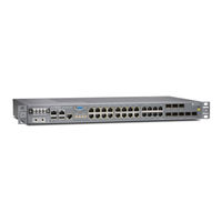
Juniper ACX2100 Hardware Manual (172 pages)
Universal Access Router
Brand:
Juniper
| Category:
Network Router
| Size: 4.31 MB
Table of Contents
Hardware Guide
1
Table of Contents
3
About the Documentation
13
Documentation Conventions
13
Junos os Documentation and Release Notes
13
Table 1: Notice Icons
14
Table 2: Text and Syntax Conventions
14
About the Documentation
15
Documentation Feedback
15
Opening a Case with JTAC
16
Requesting Technical Support
16
Self-Help Online Tools and Resources
16
ACX2000 and ACX2100 Universal Access Router Overview
19
ACX2000 and ACX2100 Hardware Components
19
ACX2000 and ACX2100 Router Description
19
ACX2000 and ACX2100 System Architecture Overview
19
Chapter 1 ACX2000 and ACX2100 Router Description
21
ACX2000 and ACX2100 Universal Access Router Overview
21
ACX2000 Router Description
22
ACX2100 Router Description
22
Figure 1: Front View of the ACX2000 Router
22
Figure 2: Rear View of the ACX2000 Router
22
ACX2000 and ACX2100 Routers Hardware and CLI Terminology Mapping
23
ACX2000 and ACX2100 Router Description
23
ACX2000 Hardware and CLI Terminology Mapping
23
Chassis
23
Figure 3: Front View of the ACX2100 Router
23
Figure 4: Rear View of the ACX2100 Router
23
Table 3: CLI Equivalents of Terms Used in Documentation for ACX2000
23
Figure 5: ACX2000 Interface Port Mapping
24
Routers
24
ACX2100 Hardware and CLI Terminology Mapping
25
Routers
25
Table 4: CLI Equivalents of Terms Used in Documentation for ACX2100
25
ACX2000 and ACX2100 Universal Access Router Overview
26
Figure 6: ACX2100 Interface Port Mapping
26
Chapter 2 ACX2000 and ACX2100 Hardware Components
27
Front Panel of an ACX2000 Router
27
Figure 10: Cooling System and Airflow in an ACX2000 and ACX2100 Router
27
Front Panel of an ACX2100 Router
28
Figure 7: Front Panel of the ACX2000 Router
28
Figure 8: Front Panel of the AC-Powered ACX2100 Router
29
ACX2000 and ACX2100 Hardware Components
29
Leds on ACX2000 and ACX2100 Routers
30
Figure 9: Front Panel of the DC-Powered ACX2100 Router
30
System LED on the Front Panel
30
Ethernet Port Leds
31
T1/E1 Port Leds
31
Table 5: System LED on the Front Panel
31
Table 6: T1/E1 Port Leds
31
Table 7: Ethernet Port Leds
31
Management and Console Port Leds on the Front Panel
32
Poe Port Leds
32
SFP and SFP+ Port Leds
32
Table 10: Management and Console Leds
32
Table 8: Poe Port Leds
32
Table 9: SFP and SFP+ Link Leds
32
Uplink Ports on ACX2000 and ACX2100 Routers
33
T1/E1 Ports
33
Table 11: T1/E1 Port Features
33
Gigabit Ethernet RJ-45 Ports
34
Table 12: RJ-45 Port Features
34
Gigabit Ethernet SFP Ports
35
Poe Ports
35
Table 13: Poe Port Features
35
Table 14: Gigabit Ethernet SFP Port Features
35
10-Gigabit Ethernet SFP+ Ports
36
Table 15: Gigabit Ethernet SFP Port Features
36
Cooling System and Airflow in an ACX2000 and ACX2100 Router
37
ACX2000 and ACX2100 Power Overview
37
ACX2000 and ACX2100 Alarm Contact Port
38
Table 16: Power Consumed by ACX2000 and ACX2100 Routers
38
Figure 11: Sample Output Alarm-Reporting Device
39
Table 17: Alarm Relay Contact Functions
39
Clocking Ports on the ACX2000 and the ACX2100 Router
40
Figure 12: Sample Input Alarm-Reporting Device
40
Chapter 3 ACX2000 and ACX2100 System Architecture Overview
43
Packet Flow on ACX Series Routers
43
Figure 13: ACX Series Router Packet Forwarding and Data Flow
43
Figure 14: ACX Series Router Packet Handling
44
Setting up the ACX2000 and ACX2100 Router
45
Installing the ACX2000 or ACX2100 Router Mounting Hardware
45
Preparing the Site for ACX2000 and ACX2100 Router Installation
45
Chapter 4 Preparing the Site for ACX2000 and ACX2100 Router Installation
47
Site Preparation Checklist for ACX2000 and ACX2100 Routers
47
Requirements
47
Table 18: Site Preparation Checklist
47
Rack Requirements for ACX2000 and ACX2100 Routers
48
Cabinet Requirements for ACX2000 and ACX2100 Routers
49
Preparing the Site for ACX2000 and ACX2100 Router Installation
49
Table 19: Rack Requirements and Specifications for the Router
49
Table 20: Cabinet Requirements and Specifications for the ACX2000 and
50
Clearance Requirements for Airflow and Hardware Maintenance on ACX2000 and ACX2100 Routers
51
Figure 15: ACX2000 and ACX2100 Chassis Dimensions and Clearance
51
General Site Guidelines for ACX Series Routers
52
Chapter 5 ACX2000 and ACX2100 Router Installation Overview
53
Installing and Connecting an ACX2000 or ACX2100 Router Overview
53
Chapter 6 Unpacking an ACX2000 or ACX2100 Router
55
Parts Inventory (Packing List) for an ACX2000 and ACX2100 Router
55
Table 21: Parts List for an ACX2000 and ACX2100 Router
55
Unpacking an ACX2000 or ACX2100 Router
56
Chapter 7 Installing the ACX2000 or ACX2100 Router Mounting Hardware
59
Installing the ACX2000 or ACX2100 Mounting Brackets
59
Figure 16: Installing the Mounting Brackets to the Front of the ACX2000 or
59
Figure 17: Installing the Mounting Brackets to the Rear of the ACX2000 or
60
Chapter 8 Installing the ACX2000 or ACX2100 Router
61
Installing the ACX2000 or ACX2100 Router in the Rack
61
Figure 18: Installing the Front-Mounted Router in the Rack
62
Chapter 9 Grounding and Providing Power to the ACX2000 or ACX2100 Router
63
Connecting the ACX2000 or ACX2100 Router to Earth Ground
63
Figure 19: Grounding Points on the ACX2000 and ACX2100 Router
64
Connecting AC Power Cords to the ACX2100 Router
65
Figure 20: Connecting AC Power to the Router
65
Connecting DC Power Cables to the ACX2000 or ACX2100 Router
66
Figure 21: Connecting DC Power to the Router
67
Chapter 10 Connecting the ACX2000 and ACX2100 Router to External Devices
69
Connecting ACX2000 or ACX2100 Routers to Management Devices
69
Connecting the Router to a Network for Out-Of-Band Management
69
Figure 22: Ethernet Cable Connector
69
Connecting the Router to a Management Console or Auxiliary Device
70
Figure 23: Ethernet Port
70
Figure 24: Routing Engine Console and Auxiliary Cable Connector
70
Device
71
Figure 25: Auxiliary and Console Connections
71
Connecting ACX2000 or ACX2100 Routers to External Clocking Devices
72
Connecting 1-PPS and 10-Mhz Timing Devices to the Router
72
Connecting a T1 or E1 External Clocking Device to the Router
72
Chapter 11 Configuring Junos os
75
Configuring Junos os
75
Initially Configuring the ACX2000 or ACX2100 Router
75
Hardware Maintenance, Troubleshooting, and Replacement Procedures
79
Troubleshooting ACX2000 and ACX2100 Hardware Components
79
Chapter 12 Maintaining ACX2000 and ACX2100 Router Hardware Components
81
Routine Maintenance Procedures for the ACX2000 and ACX2100 Router
81
Maintaining Cables that Connect to ACX2000 or ACX2100 Network Ports
81
Maintaining the ACX2000 and ACX2100 Uplink Ports
82
Chapter 13 Troubleshooting ACX2000 and ACX2100 Hardware Components
85
Troubleshooting Resources for ACX2000 and ACX2100 Routers
85
Command-Line Interface
85
Front Panel Leds
85
Understanding Alarm Types and Severity Classes on ACX Series Routers
86
Alarm Severity Classes
86
Alarm Types
86
Table 22: Alarm Terms
86
Verifying Active Alarms
87
Table 23: Alarm Output Fields
87
Monitoring System Log Messages
88
Chapter 14 Replacing ACX2000 and ACX2100 Hardware Components
89
Replacing an ACX2000 or ACX2100 Console or Auxiliary Cable
89
Figure 26: Ethernet Cable Connectors
89
Removing an ACX2000 or ACX2100 Console or Auxiliary Cable
89
Installing an ACX2000 or ACX2100 Console or Auxiliary Cable
90
Replacing an ACX2000 or ACX2100 Management Ethernet Cable
90
Figure 27: Ethernet Cable Connectors
90
Installing an ACX2000 and ACX2100 Management Ethernet Cable
90
Removing an ACX2000 or ACX2100 Management Ethernet Cable
90
Replacing an ACX2000 or ACX2100 Fiber-Optic Cable
91
Connecting an ACX2000 or ACX2100 Fiber-Optic Cable
91
Disconnecting an ACX2000 or ACX2100 Fiber-Optic Cable
91
Figure 28: Connecting a Fiber-Optic Cable to an Optical Transceiver Installed in
92
Replacing an ACX2000 or ACX2100 Transceiver
93
Removing an ACX2000 or ACX2100 Transceiver
93
Figure 29: Removing Transceivers
94
Installing an ACX2000 or ACX2100 Transceiver
94
And ACX2100 Router
95
Appendixes
97
Part 4 Appendixes
97
Safety and Regulatory Compliance Information for the ACX2000 and ACX2100 Router
99
Definition of Safety Warning Levels
99
General Safety Guidelines for Juniper Networks Devices
101
Safety Guidelines and Warnings
101
General Safety Warnings for Juniper Networks Devices
102
Qualified Personnel Warning
102
Restricted Access Area Warning
103
Router
104
Figure 30: ESD Point on ACX2000 and ACX2100 Routers
105
Figure 31: Placing a Component into an Electrostatic Bag
105
Fire Safety Requirements for Juniper Networks Devices
105
General Fire Safety Requirements
105
Fire Suppression
106
Fire Suppression Equipment
106
Installation Safety Warnings for Juniper Networks Devices
106
Installation Instructions Warning
107
Intra-Building Ports Warning
107
Rack-Mounting Requirements and Warnings
107
ACX2000 or ACX2100 Router Chassis Lifting Guidelines
111
Ramp Warning
111
General Laser Safety Guidelines for Juniper Networks Devices
112
Laser Safety Warnings for Juniper Networks Devices
112
Class 1 Laser Product Warning
113
Class 1 LED Product Warning
113
Laser Beam Warning
114
Radiation from Open Port Apertures Warning
114
Battery Handling Warning
115
Devices
115
Jewelry Removal Warning
116
Lightning Activity Warning
118
Operating Temperature Warning
118
Product Disposal Warning
119
General Electrical Safety Guidelines and Warnings
120
General Electrical Safety Warnings for Juniper Networks Devices
120
General Electrical Safety Guidelines and Electrical Codes for Juniper Networks Devices
124
ACX2100 AC Power Electrical Safety Guidelines and Warnings
125
In Case of an Electrical Accident
125
ACX2000 and ACX2100 DC Power Electrical Safety Guidelines
126
DC Power Electrical Safety Warnings for Juniper Networks Devices
127
Site Electrical Wiring Guidelines for Juniper Networks Devices
130
Agency Approvals and Compliance Statements
131
Agency Approvals for ACX2000 and ACX2100 Routers
131
Compliance Statements for EMC Requirements for ACX2000 and ACX2100
131
Routers
131
Canada
133
Compliance Statements for NEBS for ACX2000 and ACX2100 Routers
133
European Community
133
Compliance Statements for Environmental Requirements for Juniper Networks Devices
134
Israel
134
Japan
134
United States
134
Routers
137
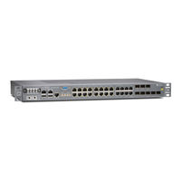
Juniper ACX2100 Hardware Manual (190 pages)
Brand:
Juniper
| Category:
Network Router
| Size: 2.71 MB
Table of Contents
Table of Contents
3
About the Documentation
9
Documentation and Release Notes
9
Using the Examples in this Manual
9
Merging a Full Example
10
Merging a Snippet
11
Documentation Conventions
11
Documentation Feedback
14
Requesting Technical Support
14
Self-Help Online Tools and Resources
15
Creating a Service Request with JTAC
15
1 Overview
16
ACX2000 and ACX2100 System Overview
17
ACX2000 and ACX2100 Universal Metro Router Overview
17
Benefits of the ACX2000 and ACX2100 Routers
18
ACX2000 Router Description
18
ACX2100 Router Description
19
ACX2000 and ACX2100 Routers Hardware and CLI Terminology Mapping
20
ACX2000 Hardware and CLI Terminology Mapping
20
ACX2100 Hardware and CLI Terminology Mapping
22
Packet Flow on ACX Series Routers
24
Protocols and Applications Supported by ACX Series Routers
26
ACX2000 Chassis Components
47
Front Panel of an ACX2000 Router
47
Front Panel of an ACX2100 Router
48
Uplink Ports on ACX2000 and ACX2100 Routers
50
T1/E1 Ports
51
Gigabit Ethernet RJ-45 Ports
52
Poe Ports
52
Gigabit Ethernet SFP Ports
53
10-Gigabit Ethernet SFP+ Ports
54
ACX2000 and ACX2100 Alarm Contact Port
54
Clocking Ports on the ACX2000 and the ACX2100 Router
56
Leds on ACX2000 and ACX2100 Routers
57
System LED on the Front Panel
57
T1/E1 Port Leds
58
Ethernet Port Leds
58
Poe Port Leds
59
SFP and SFP+ Port Leds
59
Management and Console Port Leds on the Front Panel
60
Cooling System and Airflow in an ACX2000 and ACX2100 Router
60
ACX2000 Power System
61
ACX2000 and ACX2100 Power Overview
62
ACX2100 AC Power Specifications
62
ACX2100 AC Power Cord Specifications
63
ACX2000 and ACX2100 DC Power Specifications
65
2 Site Planning, Preparation, and Specifications
67
Site Preparation Checklist for ACX2000 and ACX2100 Routers
68
ACX2000 and ACX2100 Site Guidelines and Requirements
69
General Site Guidelines
70
Site Electrical Wiring Guidelines
70
Clearance Requirements for Airflow and Hardware Maintenance on ACX2000 and ACX2100 Routers
71
Chassis Physical Specifications for ACX2000 and ACX2100 Routers
72
ACX2000 and ACX2100 Router Environmental Specifications
73
ACX2000 and ACX2100 Chassis Grounding Cable and Lug Specifications
74
Grounding Points Specifications
74
Grounding Cable Lug Specifications
75
Grounding Cable Specifications
76
Cabinet Requirements for ACX2000 and ACX2100 Routers
76
Rack Requirements for ACX2000 and ACX2100 Routers
78
ACX2000 and ACX2100 Network Cable and Transceiver Planning
80
Determining Transceiver Support and Specifications
80
Calculating Power Budget and Power Margin for Fiber-Optic Cables
81
How to Calculate Power Budget for Fiber-Optic Cable
81
How to Calculate Power Margin for Fiber-Optic Cable
82
Fiber-Optic Cable Signal Loss, Attenuation, and Dispersion
83
Signal Loss in Multimode and Single-Mode Fiber-Optic Cable
83
Attenuation and Dispersion in Fiber-Optic Cable
84
ACX2000 and ACX2100 Alarm, Management, and Clocking Cable Specifications and Pinouts
85
Alarm Contact Port Pinouts on the ACX2000 and ACX2100 Router
85
Management Port Connector Pinout Information for ACX Series Routers
87
Console or Auxiliary Port Connector Pinout on ACX Series Routers
88
USB Port Specifications for an ACX Series Router
89
Clocking Ports Specifications on the ACX2000 and the ACX2100 Router
89
External Clocking Port Connector Specifications
90
External Clocking Input Port Specifications
90
Advertisement
Juniper ACX2100 Quick Start Manual (30 pages)
Universal Metro Routers
Brand:
Juniper
| Category:
Network Router
| Size: 1.37 MB
Table of Contents
Table of Contents
1
ACX2000 and ACX2100 Quick Start Description
3
Step 1: Prepare the Site for Installation
6
Step 2: Install the Router
8
Tools Required to Install the Router in a Rack
8
Install the Mounting Brackets
8
Install the ACX Series Router in the Rack
9
Step 3: Ground the ACX2000 and ACX2100 Router
11
Tools Required to Ground the ACX Router
11
Connect the Grounding Cable
11
Step 4: Connect External Devices and Cables
14
Tools Required to Connect External Devices and Cables
14
Connect the ACX Series Router to a Network for Out-Of-Band Management
14
Connect the ACX Series Router to a Management Console or Auxiliary Device
15
Connect Network Interface Cables to the ACX Series Router
15
Step 5: Connect Power to the ACX Series Router
17
Connect AC Power to an AC-Powered ACX2100 Series Router
17
Connect DC Power to a DC-Powered ACX2000 or ACX2100 Router
18
Step 6: Perform Initial Software Configuration
21
Enter Configuration Mode
21
Configure User Accounts and Passwords
22
Configure System Attributes
22
Commit the Configuration
23
Safety Warnings
25
Compliance Statements for NEBS
26
Compliance Statements for EMC Requirements
27
Canada
27
European Community
27
Israel
27
Japan
28
United States
28
Junos os Documentation and Release Notes
29
Requesting Technical Support
29
Self-Help Online Tools and Resources
29
Creating a Service Request with JTAC
30
Revision History
30
Juniper ACX2100 Quick Start Manual (30 pages)
Universal Metro Routers
Brand:
Juniper
| Category:
Network Router
| Size: 1.32 MB
Table of Contents
Table of Contents
1
ACX2000 and ACX2100 Quick Start Description
3
Step 1: Prepare the Site for Installation
6
Step 2: Install the Router
8
Tools Required to Install the Router in a Rack
8
Install the Mounting Brackets
8
Install the ACX Series Router in the Rack
9
Step 3: Ground the ACX2000 and ACX2100 Router
11
Tools Required to Ground the ACX Router
11
Connect the Grounding Cable
11
Step 4: Connect External Devices and Cables
14
Tools Required to Connect External Devices and Cables
14
Connect the ACX Series Router to a Network for Out-Of-Band Management
14
Connect the ACX Series Router to a Management Console or Auxiliary Device
15
Connect Network Interface Cables to the ACX Series Router
15
Step 5: Connect Power to the ACX Series Router
17
Connect AC Power to an AC-Powered ACX2100 Series Router
17
Connect DC Power to a DC-Powered ACX2000 or ACX2100 Router
18
Step 6: Perform Initial Software Configuration
21
Enter Configuration Mode
21
Configure User Accounts and Passwords
22
Configure System Attributes
22
Commit the Configuration
23
Safety Warnings
25
Compliance Statements for NEBS
26
Compliance Statements for EMC Requirements
27
Canada
27
European Community
27
Israel
27
Japan
28
United States
28
Junos os Documentation and Release Notes
29
Requesting Technical Support
29
Self-Help Online Tools and Resources
29
Creating a Service Request with JTAC
30
Revision History
30
Juniper ACX2100 Quick Start Manual (26 pages)
Universal Access Routers
Brand:
Juniper
| Category:
Network Router
| Size: 0.75 MB
Table of Contents
Table of Contents
1
ACX2000 and ACX2100 Quick Start Description
3
Step 1: Prepare the Site for Installation
6
Step 2: Install the Router
8
Tools Required to Install the Router in a Rack
8
Install the Mounting Brackets
8
Install the ACX Series Router in the Rack
9
Step 3: Ground the ACX2000 and ACX2100 Router
10
Tools Required to Ground the ACX Router
10
Connect the Grounding Cable
10
Step 4: Connect External Devices and Cables
12
Tools Required to Connect External Devices and Cables
12
Management
12
Device
12
Connect Network Interface Cables to the ACX Series Router
12
Step 5: Connect Power to the ACX Series Router
14
Connect AC Power to an AC-Powered ACX2100 Series Router
14
Connect DC Power to a DC-Powered ACX2000 or ACX2100 Router
14
Step 6: Perform Initial Software Configuration
18
Enter Configuration Mode
18
Configure User Accounts and Passwords
18
Configure System Attributes
19
Commit the Configuration
19
Safety Warnings
21
Compliance Statements for NEBS
22
Router
22
Canada
22
European Community
22
Declaration of Conformity
22
Junos os Documentation and Release Notes
25
Requesting Technical Support
25
Self-Help Online Tools and Resources
25
Opening a Case with JTAC
26
Revision History
26
Advertisement
Related Products
Juniper ACX2000
Juniper ACX2200
Juniper ACX1100
Juniper ACX4000
Juniper ACX5048
Juniper ACX500
Juniper ACX5096
Juniper ACX5448
Juniper ACX Series
Juniper ACX6160
Juniper Categories
Network Router
Switch
Gateway
Software
Network Hardware
More Juniper Manuals
Login
Sign In
OR
Sign in with Facebook
Sign in with Google
Upload manual
Upload from disk
Upload from URL