Sign In
Upload
Manuals
Brands
JUKI Manuals
Industrial Equipment
RS-1R
JUKI RS-1R Manuals
Manuals and User Guides for JUKI RS-1R. We have
2
JUKI RS-1R manuals available for free PDF download: Maintenance Manual, Repacking Manual
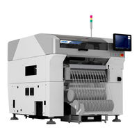
JUKI RS-1R Maintenance Manual (361 pages)
Fast Smart Modular Mounter
Brand:
JUKI
| Category:
Racks & Stands
| Size: 37.14 MB
Table of Contents
Table of Contents
3
X-Y Unit
10
Replacing the Servomotor
10
Replacing the X-Motor
10
Replacing the YL-Motor
11
Replacing the YR-Motor
14
Replacing the Limit Sensor and Origin Near Sensor
17
Replacing the X-Axis Limit Sensor and the X-Axis Home Proximity Sensor
17
Replacing the Y-Axis Limit Sensor and the Y-Axis Home Proximity Sensor
19
Checking the Sensor Operation
21
Replacing the Cableveyor
22
Replacing the X-Axis Cableveyor
22
Replacing the Y-Axis Cableveyor
23
Replacing the Cables in the X/Y Veyor-Cable
25
Removing the X Cable
25
Checking the Cable Marking (X)
28
Assembling the Cable
29
Removing the y Veyor-Cable
32
Assembling the Cable
33
Wiring Around the Head
36
Replacing the Cableveyor Link
37
Cableveyor Structure and Part Names
37
Detaching the Arm and Lock Stay
37
Separating the Link
38
Connecting the Cableveyor
38
Mounting the Arm and Lock Stay
39
Replacing the X Ball Screw
40
Preparations for X Ball Screw Replacement
40
Removing the X Ball Screw
43
Mounting the X Ball Screw
46
Adjusting the X Ball Screw
49
Replacing the y Ball Screw
53
Preparations for y Ball Screw Replacement
53
Removing the y Ball Screw
56
Mounting the y Ball Screw
63
Adjusting the y Ball Screw
68
Readjustment after XY Part Exchange
75
Head
76
8-Nozzle Head
76
Replacing the Head Unit
76
Replacing the Z-Motor
84
Replacing the Θ-Motor
89
Replacing the Timing Belts Z
93
Replacing the Timing Belt Θ
93
Replacing the Ball Screw
95
Replacing the LNC120-8
99
Replacing the Z-Slide Shaft
100
Replacing the Head up Cylinder
101
Replacing the Θ-Origin Sensor
103
Replacing the ZA-Motor
106
Replacing the Head Unit (When the Head Revision Number Is a or Later)
107
Replacing the Z-Motor (When the Head Revision Number Is a or Later)
114
Replacing the Θ-Motor (When the Head Revision Number Is a or Later)
124
Replacing the Timing Belt Z (When the Head Revision Number Is a or Later)
127
Replacing the Timing Belt Θ (When the Head Revision Number Is a or Later)
127
Replacing the Ball Screw (When the Head Revision Number Is a or Later)
128
Replacing the LNC120 (When the Head Revision Number Is a or Later)
131
Replacing the Z-Slide Shaft (When the Head Revision Number Is a or Later)
131
Replacing the Θ-Origin Sensor (When the Head Revision Number Is a or Later)
134
Readjustment after Replacement of Head Unit
137
Parts Around the Head
138
Solenoid Valve Unit
138
Replacing the Solenoid Valves
138
Replacing the Filter
139
Replacing the Filter for Release to Atmosphere
139
Replacing the HMS
140
Replacing the Electromagnetic Valve
141
Replacing the Head Board
142
Replacing the Head Main Board
142
Replacing the Servo Amplifier Board
143
OCC Unit
144
Replacing the OCC Unit
144
Replacing the CCD Camera and Lens
145
Replacing the OCC Coaxial/Angle Light Board
146
Replacing the Lens Filter
147
Adjusting the Focus and the OCC Light Quantity
148
Readjustment Items after Replacing OCC Unit
148
Board Transport
149
Replacing the Transport Belt
149
Replacing the Transport Pulley
150
Transport Pulley a Assembly: E21117150A0
150
Transport Pulley B Assembly: E20897210A0
150
Replacing the Conveyor (Board Transport) Motor
151
Replacing the AWC (Board Width Adjustment) Motor
154
Replacing the Timing Belt
155
Replacing the Timing Belt for Adjustment of the Transport Width
155
Replacing the Conveyor Motor Timing Belt
156
Replacing the Transport Width Adjustment Connection Timing Belt
157
Replacing the LEFT/RIGHT Sensors
159
Adjusting the Sensor Sensitivity
160
Replacing the STOP Sensor
161
Replacing the Front STOP Sensor Fiber
161
Replacing the Rear STOP Sensor Fiber
163
Replacing the Fiber Amplifier
165
Replacing the BU Pin Detection Sensor
168
Replacing the Support Table Origin Sensor (BU Origin Sensor)
169
Replacing the AWC Origin Sensor
170
Replacing the Support Table Motor (BU Table Motor)
171
Removing the Support Table
171
Support Table Motor
172
Adjusting the Tension of the Support Table Driving Timing Belt
173
Placing the Support Table Surface Horizontally
173
Reacquiring the Support Table Offset
173
Replacing the Backup Stopper
177
Replacing the Support Guide Cylinder
178
Switching the Conveyor Direction
179
Replacing the Mechanical Stopper
184
Replacing the Stopper Sensor
184
Replacing the Stopper Cylinder
185
Cal Block
186
Replacing the CAL Block Board Assembly
186
Replacing the Ejector
187
Atc
188
Replacing the Air Cylinder
188
Replacing the ATC OPEN and CLOSE Sensors
190
Adjusting the Speed Controller
190
Feeder Bank
191
Replacing the Bank PCB
192
Replacing the FDC
194
Replacing the Slide Rail
195
Replacing the Bank Connector a (Exchange Trolley Only)
196
Replacing the Inline Filter (Exchange Trolley Only)
197
Bank Lifter
198
Replacing the Mechanical Valve
198
Replacing the Bank up Cylinder
199
Replacing the Selector
200
Replacing the Bank Connector B
201
Replacing the Actuator Valve
202
Replacing the O-Ring
202
Replacing the Bank Limit Switch (en Only)
203
Tape Cutter
204
Overall Drawing
204
Replacing the Tape Cutter Blade
205
Feeder Float Sensor
214
Layout
214
Replacing the Light Receiving Side Sensor
216
Replacing the Light Emitting Side Sensor
216
Switch Related
219
Replacing the Push-Button Switch
219
Replacing the EMERGENCY STOP Switch
221
Replacing the Cover Open Switch
223
Replacing the Safety Cover Lock Cylinder
224
Replacing the Assist Hinge
227
Electrical Components
228
Layout of Electrical Components
228
Electrical Component Unit
230
Electrical Component Unit a
230
Electrical Component Unit B
233
Control Unit
240
Cpu Board (40123242)
241
Io Control Pcb Asm (40128871)
249
Position Board (40129648)
251
Ip-X11 Set Gen Asm (49133294)
252
Superimpose Board (40129641)
253
ATX Power Supply
254
Battery Unit
255
XY-Driver Unit
256
Structure of XY Unit
256
Adjustment Items after Replacement of XY Driver
257
Display Indication of XY Servo Amplifier
257
Z,T Unit
258
Configuration of 8-Nozzle Head
259
Transport Unit
262
Structure of Transport Unit
262
Connecting the CONVEYOR Board and Sensors
263
Connecting the Transport Motor
265
List of Other Sensors, Solenoid Valves, and Cable Assemblies
266
Conveyor Pcb Asm (40128875)
267
Adjusting the Stepping Motor Driver
268
Safety Pcb Asm (40128872)
271
Head Unit
273
Head Main Pcb Asm (40128873)
273
Head Relay Pcb Asm (40128874)
274
E Bank Relay Pcb Asm (40128876)
275
Outside View of Board
275
Setting the Switches
275
Adjusting the Volumes
275
Others
276
Light Control Pcb Asm (40132991)
276
Replacing the Filter Element
277
Replacement of Vacuum Pump Parts
278
Other Units
286
LCD Monitor
286
Replacing the LCD Monitor
286
Setting up the Touch Panel
287
Replacing the System Disk
290
Replacing the SSD
290
Setting up the Network
292
System Programs
303
Upgrading the RS-1 System Version
311
Mcafee Embedded Control
316
Janets (ISM/MES Cooperation) Option
317
Replacing the Bar-Code Reader
317
Operation Check after Replacement
318
Initial Setting after Replacement (Pick Mode)
319
Tape Setting Unit
320
Replacement of the Connector Cable
320
Replacement of the Slide Rail
320
Vcs
321
Replacing the VCS Cylinder (Up-Down Cylinder)
321
Replacing the VCS Sensor (Up-Down Sensor)
326
Replacing the VCS Camera Switching Cylinder
327
Replacing and Adjusting the Camera
329
Solder Recognition and Placement Position Correction
332
Replacing the Solder Recognition Light Board
332
Light Quantity of the Solder Recognition Light
333
Load Cell
334
Replacing the Load Cell
334
Coplanarity Sensor
336
Replacing the Sensor
337
Changing the IP Address of the Coplanarity CPU
339
Required Parts
339
Setting Preparations
339
Changing the Coplanarity CPU Setting
340
Changing the Mounter Setting
344
Cvs
349
Changing the CONTACT SUB UNIT
349
Changing the CVS Board
352
Nozzle RFID READER
353
Changing the RFID READER/WRITER
353
Appendix Jig Lists
355
Appendix List of Measuring Instruments
358
Advertisement
JUKI RS-1R Repacking Manual (36 pages)
Fast Smart Modular Mounter
Brand:
JUKI
| Category:
Industrial Equipment
| Size: 5.19 MB
Table of Contents
Table of Contents
3
Chapter 1 Head Unit
4
Securing the Head Unit Fixing Parts
4
Securing the LNC Z-Axis Fixing Parts
4
Securing the ZA-Axis
5
Attaching the Packing Materials
6
Securing the Head Unit Fixing Parts (Head Rev. a and Later)
7
Securing the LNC Z-Axis Fixing Parts
7
Securing the ZA-Axis
8
Attaching the Packing Material (Head Rev. a and Later)
8
Chapter 2 X-Y Unit
9
Securing the X-Axis Frame
9
Securing the Head
10
Chapter 3 Board Transport Unit
11
Packing the Accessory Units
11
Packing Procedure
12
Center Part
12
Left and Right End Parts
12
Chapter 4 Base Bridge Section
13
ATC Unit
13
General View of Base Bridge (ATC and VCS Light Units)
14
Chapter 5 Signal Light
15
Chapter 6 Safety Cover
16
Chapter 7 Pneumatic Units
18
Chapter 8 Electric Fixed Bank
19
Detaching the Packing Parts
19
Packing Procedures
19
Chapter 9 LCD Monitor
21
Chapter 10 Overall Machine Cover
22
Chapter 11 Packing the Accessory Units
24
Outer Carton Case
24
Check List for Units and Components to be Put in the Carton Box
25
Chapter 12 Transport Extension (Option)
26
Chapter 13 Other Optional Units
27
Chapter 14 Feeder Exchange Trolley
28
Chapter 15 Tape Set Unit (Machine Rev. D and Later)
32
Chapter 16 Touch Pen (RS-1R Only)
34
Advertisement
Related Products
JUKI RS-1
JUKI RS-1XL
JUKI RF04AS
JUKI RF08AS
JUKI RF12AS
JUKI RF16AS
JUKI RF24AS
JUKI RF44AS
JUKI RF56AS
JUKI RF88AS
JUKI Categories
Sewing Machine
Industrial Equipment
Sewing Machine Accessories
Accessories
Measuring Instruments
More JUKI Manuals
Login
Sign In
OR
Sign in with Facebook
Sign in with Google
Upload manual
Upload from disk
Upload from URL