Sign In
Upload
Manuals
Brands
Jonker Sailplanes Manuals
Aircrafts
JS3 RES
Jonker Sailplanes JS3 RES Manuals
Manuals and User Guides for Jonker Sailplanes JS3 RES. We have
1
Jonker Sailplanes JS3 RES manual available for free PDF download: Maintenance Manual
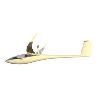
Jonker Sailplanes JS3 RES Maintenance Manual (180 pages)
Brand:
Jonker Sailplanes
| Category:
Aircrafts
| Size: 6.85 MB
Table of Contents
Table of Contents
8
List of Figures
11
General
15
Descriptive Data
15
Technical Data
15
Figure 1-1 JS3 with RES Pylon Extended
15
Table 1-1 RES Technical Data
15
Description of Systems and Components
17
Introduction and Overview
17
Figure 2-1 RES System Overview
17
RES Kinematics Overview
18
Figure 2-2 Kinematics Layout Overview
18
Electrical System Overview
19
Figure 2-3 Electrical System Overview
19
Figure 2-4 Electrical Interaction Overview
21
Table 2-1 Electrical Loads
21
Airworthiness Limitations and Inspections
23
Airworthiness Limitations
23
Table 3-1 Life Limits Durations
23
Maintenance Schedule
25
Annual Inspection
25
Table 4-1 Maintenance Requirement Schedule
25
RES Actuator Assembly
26
Figure 4-1 RES Actuator Assembly
26
Figure 4-2 Actuator Assembly
28
Table 4-2 Actuator Specifications
28
Figure 4-3 Pylon Bell Crank Assembly
29
Figure 4-4 Pylon Bell Crank Bracket Assembly
31
Figure 4-5 Pylon Driver Arm Assembly
33
RES Pylon
35
Propeller
36
Figure 4-6 Pylon Assembly
36
Figure 4-7 Motor Wires Routing
38
Figure 4-8 Propeller Assembly
39
Electrical Motor
43
Figure 4-9 Electrical Motor
43
RES Doors
46
Front Doors
46
Figure 4-10 Doors Assembly
46
Figure 4-11 Main Door Bell Crank Assembly
48
Figure 4-12 Main Doors Assembly
50
Figure 4-13 Front Doors Assembly
52
Battery Latches
54
Figure 4-14 Battery Latches
54
Display and Control Unit (DCU)
56
Figure 4-15 DCU
56
LXNAV Bridge
59
Motor Controller Assembly
60
Figure 4-16 Motor Controller Overview
61
Figure 4-17 Motor Controller Assembly
61
Figure 4-19 Motor Controller Pcbs
64
Figure 4-22 HV Wire
69
DC-DC Converter
81
Figure 4-20 Cooling Fans
84
Figure 4-21 Motor Controller HV Wire Sequence
84
Table 4-3 DC-DC Converter Specifications
94
Retraction and Fuses Unit (RFU)
97
Insulation Monitoring Device (IMD)
98
HV Connectors
99
Avionic Batteries
103
Table 4-4 Seatpan Battery Specification
103
Fire Warning System
104
Calibration & Setup
106
Actuator System Setup
106
Figure 5-1 Fuselage Clearance
107
Figure 5-2 Pylon Driver Arm Extension
107
Figure 5-3 B9 Bulkhead
108
Actuator Calibration
109
Main Door Setup
109
Motor Resolver Calibration
110
Figure 5-4 Main Door Setup
110
Propeller Alignment
111
Wiring Loom
114
Display and Control Unit (DCU)
114
Figure 6-1 DCU Wiring
114
RES Control Board (RCB)
115
Figure 6-2 RCB Wiring
115
Retraction and Fuses Unit (RFU)
117
Actuator
117
Figure 4-24 RFU
118
Figure 6-3 RFU Wiring
118
Figure 6-4 Actuator Wiring
118
Left Battery Connector
119
Figure 6-5 Left Battery Connector Wiring
119
Charger Connector
120
Right Battery Connector
120
Figure 6-6 Charger Connector Wiring
120
Figure 6-7 DC-DC Converter
121
Figure 6-8 Right Battery Connector Wiring
122
Motor, Motor Controller and Resolvers
123
Figure 6-9 Motor, Motor Controller, and Resolvers Wiring
123
Cooling Fans
124
Figure 6-10 Cooling Fans Wiring
124
Insulation Monitoring Device (IMD)
125
Figure 6-11 IMD Wiring
125
Avionic Batteries
126
Figure 6-12 Avionics Battery Wiring
126
Ground Bus
127
Figure 6-13 Ground Bus Wiring
127
Supplementary Fire Warning System
128
Figure 6-14 Supplementary Fire Warning System Wiring
128
LXNAV Bridge
129
Complete Schematic
130
Supplementary Information and Pictures
131
Lubrication
133
Introduction
133
Lubricants
133
Lubrication Plan
133
Figure 7-1 Lubrication Points
134
System Operation
135
Guarded RES Master Switch
135
Figure 8-1 Guarded RES Master Switch
135
Display and Control Unit Interface
136
Battery Selection Switch
136
Figure 8-2 DCU Primary Controls
136
Operational Mode
137
Figure 8-3 Standby Screen
137
Figure 8-4 Extension/Retraction Screen
138
Figure 8-5 Extended Screen
139
Figure 8-6 Propulsion Screen
140
Figure 8-7 Battery Charging Screen
141
Other Information Screens
142
Figure 8-9 Message Screen
142
Figure 8-10 System Screen
143
Warning Caution and Information Messages
144
Figure 8-11 Warning Screen
144
Maintenance Mode
145
Setup Menu
145
Figure 8-12 Service Screen
145
Figure 8-13 Setup Screen
145
Charge Mode
146
Fire Warning System
146
Figure 8-14 Fire Warning System
146
Software/ Firmware Update
147
Requirements for Firmware Updated
147
DCU Firmware Update
147
RFU Firmware Update
148
Accessing the Motor Controller Parameters
149
Figure 9-1 Adapter Installation
149
10 High Voltage Batteries
151
Overview
151
Figure 10-1 Battery Overview
151
Inspections
152
Trailer Considerations
152
Battery Status Indicators
153
Figure 10-2 Battery Status Indicators
153
Battery Handling
154
Installing the HV Batteries
154
Battery Care
155
Long Term Storage
155
Figure 10-3 Dual Battery Operation
155
Figure 10-4 Single Battery Operation
155
Charging
157
Figure 10-5 Dual Battery in Aircraft Charging
157
Figure 10-6 Single Battery in Aircraft Charging
158
Figure 10-7 External Dual Battery Charging
158
Figure 10-8 External Single Battery Charging
159
11 Placard Booklet
160
Figure 11-1 RES Placard Booklet
160
13 Service Bulletins
163
14 Contact
166
APPENDIX A - Annual Inspection Checklist
168
APPENDIX B - General Torque Specifications
172
APPENDIX C - Stcs and Minor Change Approvals
174
Appendix D - List of Warnings/Cautions
176
Advertisement
Advertisement
Related Products
Jonker Sailplanes JS-MD 3
Jonker Sailplanes JS3
Jonker Sailplanes JS1 Series
Jonker Sailplanes JS1-B
Jonker Sailplanes JS1C-18m
Jonker Sailplanes JS1C-21m
Jonker Sailplanes JS1-A
Jonker Sailplanes JS1 Revelation
Jonker Sailplanes Categories
Aircrafts
Tools
GPS
Control Systems
More Jonker Sailplanes Manuals
Login
Sign In
OR
Sign in with Facebook
Sign in with Google
Upload manual
Upload from disk
Upload from URL