Sign In
Upload
Manuals
Brands
JLG Manuals
Lifting Systems
Toucan 32E
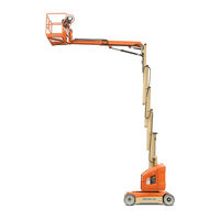
JLG Toucan 32E Mast Boom Lift Manuals
Manuals and User Guides for JLG Toucan 32E Mast Boom Lift. We have
3
JLG Toucan 32E Mast Boom Lift manuals available for free PDF download: Service And Maintenance Manual, Operation And Safety Manual
JLG Toucan 32E Service And Maintenance Manual (205 pages)
Personal lifts
Brand:
JLG
| Category:
Lifting Systems
| Size: 10.07 MB
Table of Contents
Section a - Introduction - Maintenance Safety Precautions Revison Log
5
Section a - Introduction - Maintenance Safety Precautions
3
Bhydraulic System Safety
3
Cmaintenance
3
A General
3
Table of Contents
5
Section 1 - Operating Specifications
15
Operating Specifications
15
Dimensional Data
15
JLG Lift
15
Performance Data
16
Capacities
16
Components Data
17
Batteries
17
Drive Motor Assembly
17
Electric Pump / Electric Motor Assembly
17
Cylinders
18
Platform Rotation Drive
18
Swing Drive
18
Tires
18
Major Components Weights
19
Lubrication
20
Hydraulic Oil
20
Lubrication Chart
21
Lube Specifications
22
Torque Requirements
22
Serial Number Locations
23
Section 2 - General Service Information
25
Machine Preparation, Inspection and Maintenance
25
Annual Machine Inspection
25
General
25
Pre-Delivery Inspection and Frequent Inspection
25
Pre-Start Inspection
25
Preparation, Inspection and Maintenance
25
Preventative Maintenance
25
Preventive Maintenance and Inspection Schedule
26
Inspection and Preventive Maintenance Schedule
27
Bearings
30
Care and Installation of Teflon Coated Bushings
30
Cleanliness
30
Component Disassembly and Reassembly
30
Components Removal and Installation
30
General
30
Pressure-Fit Parts
30
Safety and Workmanship
30
Servicing and Maintenance Guidelines
30
Bolt Usage and Torque Application
32
Hydraulic Lines and Electrical Wiring
32
Hydraulic System
32
Battery
33
Changing Hydraulic Oil
33
Hydraulic Oil
33
Hydraulic System
33
Lubrication
33
Lubrication Information
33
Lubrication Specifications
33
Pressure Relief Valve
33
Welding on Work Platform
33
Hydraulic Cartridge Installation
34
Section 3 - Theory of Operation
35
Overview
35
Modes of Operation
35
Ground Mode
35
Platform Mode
35
Can Communications
35
Joysticks
36
Traction
36
Pump/Structure Movements
37
Lift Up/Down
37
Hydraulic Pump Electric Schematic
37
Swing
38
Steer
39
Telescope
39
Telescope System - Basic Schematic
39
Interlocks
40
Platform Level
40
Personality Settings and Calibration
41
Section 4 - Chassis Mounted Components
43
Drive Motors
43
Brake - Dust Cleaning
43
Brake - Electrical Characteristics
43
Brake Disassembly
43
Brake Disk Wear Checking
43
Dust Cleaning
43
Brake Assembly
44
Drive Motor Assembly Removal
44
Drive Motor Assembly Installation
45
Oil Filling
45
Oil Type & Capacity
45
Drive Motor Installation
45
Tire Wear and Damage
46
Wheel and Tire Replacement
46
Wheel Installation
46
Wheels and Tires
46
Wheel Lug Nut Tightening Sequence
46
Steer Cylinder
47
Steering Linkage
47
Steering Linkage - Spindle/Hub Assembly
47
Steering Sensor Installation
48
Section 5 - Turntable and Vertical Mast
49
Swing Bearing
49
Swing Bearing Attach Bolts Check
49
Swing Bearing Lubrication
49
Swing Bearing Race Lubrication
49
Swing Bearing Teeth Lubrication
49
Replacement of Swing Bearing
50
Swing Bearing Removal - 1 of 6
50
Swing Bearing Removal - 2 of 6
50
Swing Bearing Removal - 3 of 6
50
Swing Bearing Removal - 4 of 6
50
Swing Bearing Removal - 5 of 6
50
Swing Bearing Removal - 6 of 6
50
Swing Drive
52
Swing Drive Removal
52
Swing Bearing Installation
52
Inspection
53
Removal and Installation
53
Rollers
53
Swing Drive Assembly
53
Swing Drive Disassembly
53
Swing Drive Installation
53
Roller Assembly
53
Mast Transversal Play/Mast Sections Alignment
54
Roller Removal
54
Roller Installation
54
Mast Sections Vertical Alignment
54
Lifting Chains
55
Lubrication
55
Safety Accessories and Tooling
55
Lifting Chains Inspection
56
Lifting Chains Removal and Installation
57
Chains Stages and Attachments Description
57
First Chain Stage
58
Third Chain Stage
59
First Chains Stage Removal
60
Second Chains Stage Removal
61
Third Chains Stage Removal
62
Fourth Chains Stage Removal
63
Chain Tension Adjustment
64
Pulley - Pulley Support
64
Pulley Inspection
64
Chains Tension Control
64
Removal and Installation
65
Mast Cylinder
66
Mast Cylinder Removal
66
Mast Cylinder Removal - 4 of 8
67
Mast Cylinder Disassembly
68
Mast Cylinder Installation
68
Counterweight
69
Counterweight Installation
69
Counterweight Removal
69
Section 6 - Telescopic Boom and Platform
71
Overlaod System
71
Overload System Setting
71
Overload System Verification
71
Platform
71
Platform Removal
71
Platform Installation
72
Platform Supports and Slave Cylinder
72
Platform Supports and Slave Cylinder Removal
72
Platform Support and Slave Cylinder Removal - 1 of 4
72
Platform Rotation Option (if Equipped)
72
Platform Support and Slave Cylinder Removal - 2 of 4
72
Platform Support and Slave Cylinder Removal - 3 of 4
72
Platform Support and Slave Cylinder Removal - 4 of 4
72
Boom and Cylinders Removal
74
Platform Supports and Slave Cylinder Installation
74
Slave Cylinder Disassembly
74
Telescopic Boom, Boom and Master Cylinders
74
Boom and Cylinders Installation
75
Boom and Master Cylinders Disassembly
75
Boom Disassembly
75
Telescope
75
Telescope Sections and Cylinder Removal
75
Telescope Toucan 12E Plus
75
Telescope Dual Cylinder Disassembly
76
Telescope Sections and Cylinder Installation
76
Telescope Sections and Cylinder Removal
76
Telescope Toucan 12E / Toucan 32E
76
Telescope Cylinder Disassembly
77
Telescope Sections and Cylinder Installation
77
Section 7 - Hydraulics
79
Hydraulic Lines Connections
79
Hydraulic Power Unit
80
Ports Identification
80
Proportional Pressure Relief Valve
80
Check Valve 0.5 Bar
81
Check Valve 4.5 Bar
81
Electric Motor
81
Dust Cleaning
81
Adding Oil to the System
82
Hydraulic Tank
82
Oil Level
82
Hydraulic Oil Check
82
Main Manifold
83
Manifold Schematic
83
Tank Draining/Cleaning
83
Tank Filling
83
Assembly
84
Disassembly
84
Inspection
84
Hand Pump
84
Assembly
85
Disassembly
85
Inspection
85
Manifold Schematic
85
Secondary Manifold
85
Cylinders Holding Valves
86
Jib Cylinder Holding Valve
86
Mast Cylinder Holding Valve
86
Jib Cylinder Holding Valve - Schematic/Exploded View
87
Slave Cylinder Holding Valve
88
Telescope Cylinder Holding Valve
88
Adjustment Checking
89
Air Bleeding from Rod Side
89
Swing Motor
90
Air Bleeding from Piston Side
90
Cylinder Repair
91
Telescope Plus Cylinder
94
Assembly
95
Disassembly
95
Inspection
95
Section 8 - Control Components
97
Control Components Overview
97
Control Components Location
97
Battery Maintenance and Safety Practices
98
Control Components - Service
98
Draining the Water
99
Battery Troubleshooting
100
Main Power Contactor Relay
101
Power Fuse
101
Jib Elevation Limit Switches
102
Mast Elevation Limit Switch
102
Mast Elevation Limit Switches
102
Chain Slack Sensor
103
Overload Sensor
104
Overload System Calibration
104
Drive Orientation Switch
105
Steering Sensor
105
Tilt Sensor
106
Common Traction System Difficulties
107
Traction System
107
Power Module
108
Removal
108
Installation
109
Power Module Electrical Evaluation
110
Ground Control Station
112
Ground Module
112
Ground Control Station Connectors - 2 of 3
113
Ground Control Station Connectors - 3 of 3
114
Membrane Panel
115
Printed Circuit Board (PCB) Replacement
115
Platform Control Station
116
Printed Circuit Board (PCB) Replacement
116
Upper Control Box - Component Replacement
116
Upper Control Box - Components Evaluation
117
Section 9 - Jlg Control System
119
Hand Held Analyzer
119
Analyzer Menu Structure
119
Hand Analyzer
120
Using the Analyzer
120
Changing the Access Level of the Hand Held Analyzer
121
Adjusting Parameters Using the Hand Held Analyzer
122
Machine Setup
123
Analyzer Screen Layout
124
Analyzer Flow Chart - Sheet 2 of 2
125
Machine Setup Programming Information
126
Calibrating Steering Sensor
128
Calibrating the Joysticks
128
Calibrating Tilt Sensor
128
Calibration Instructions
128
Calibrating the Pressure Relief Valve
129
Machine Personality - Adjustment Settings
130
System Test
135
Section 10 - Diagnostic Trouble Codes Section 10. Diagnostic Trouble Codes 10.1 Introduction
137
Section 10 - Diagnostic Trouble Codes
137
Introduction
137
Dtc Index
137
10.2 Dtc Index
138
Dtc Check Tables
138
Help Comments
138
Power-Up
140
Platform Controls
140
Ground Controls
143
Function Prevented
148
Line Contactor Open Circuit
150
Line Contactor Short Circuit
150
Ground Output Driver
152
Thermal Limit
159
Battery Supply
162
Transmission and Drive System
165
Communication
166
Accessory
169
Electric Motor
169
Tilt Sensor
172
Platform Load Sense
173
Steering/Axle
173
Safety System Override
177
Hardware
177
General
183
Resistance Measurement
184
Current Measurement
185
Automatic Switches
186
Amp Connector
187
Connector Assembly Figure 2
188
Disassembly
189
Connector Installation
190
Deutsch Connectors
191
HD30/HDP20 Series Assembly
192
Connectors Identification
193
Wiring Harness and Connectors - Sheet 2 of 3
194
Wiring Harness and Connectors - Sheet 3 of 3
195
Electrical Schematic
196
Electrical Schematic - Turntable
197
Electrical Schematic - Lower Control Board
198
Electrical Schematic - Mast
199
Electrical Schematic - Platform Box
200
Electrical Schematic - Batteries
201
Hydraulic Schematic
202
Advertisement
JLG Toucan 32E Operation And Safety Manual (115 pages)
Brand:
JLG
| Category:
Lifting Systems
| Size: 8.07 MB
Table of Contents
Table of Contents
8
Section 1. Safety Precautions
15
General
15
Pre-Operation
15
Operator Training and Knowledge
15
Workplace Inspection
16
Machine Inspection
17
Operation
18
General
18
Trip and Fall Hazards
19
Electrocution Hazards
20
Minimum Approach Distance (M.A.D.)
20
Tipping Hazards
21
Beaufort Scale (for Reference Only)
22
Crushing and Collision Hazards
24
Towing, Lifting, and Hauling
25
Maintenance
25
Maintenance Hazards
25
Battery Hazards
26
Section 2. User Responsibilities, Machine Preparation, and Inspection
28
2.1 Personnel Training
28
Operator Training
28
Training Supervision
29
Operator Responsibility
29
Preparation, Inspection, and Maintenance
29
Inspection and Maintenance Table
30
Pre-Start Inspection
31
Daily Walk-Around Inspection
32
Daily Walk-Around Inspection
34
Function Check
35
Overload Sensor Check
37
Overload Sensor
37
Section 3. Machine Controls, Indicators and Operation
39
General
39
Description
39
Operating Characteristics and Limitations
40
General
40
Placards
40
Capacities
40
Platform Loading
40
Stability
41
Position of Least BACKWARD Stability
42
Position of Least FORWARD Stability
42
Basic Nomenclature - Machine Control Locations
43
Machine Control Locations
43
Controls and Indicators
44
Ground Control Station
44
Ground Control Station
45
Platform Manual Descent Valves
48
Flow Control Valve
49
Mast Manual Descent Valve and Actuator
50
Mast Manual Descent Actuator Installation
50
Boom Manual Descent Valve
51
Manual Swinging Operating Devices
52
Boom Manual Lift up Valve
53
Platform Control Station
54
Platform Control Indicator Panel
55
Grade and Side Slope
59
Grade and Side Slope
60
Operation
61
Steering and Traveling (Driving)
61
Steering
62
Traveling (Driving)
62
Drive Orientation System (DOS)
63
3.11 Platform
64
Platform Level Adjustment
64
Platform Rotation (if Equipped)
64
3.12 Raising and Lowering the Platform
65
Raising and Lowering the Mast
65
Raising and Lowering the Boom
65
Telescoping the Boom
65
3.13 Swinging
66
3.14 Alarms
66
Overload Warning Light/Alarm
66
Tilt Warning Light/Alarm
66
Slack Chain Warning Light/Alarm
67
Machine Safety System Override (Msso)
68
3.16 Shut down and Park
69
3.17 Battery Charging
70
Battery Charger Fault Code
71
3.18 Tie-Down/Lift Lugs
72
Tie down
72
Machine Tie-Down
72
Lifting
73
3.19 Towing
73
Lifting the Machine
73
Electric Brake Release
74
Section 4. Emergency Procedures
76
General Information
76
Emergency Operation
76
Operator Unable to Control Machine
76
Platform or Boom Caught Overhead
76
Emergency Control
77
Emergency Controls
77
Platform Manual Descent
78
Incident Notification
78
Emergency Towing
78
Machine Safety System Override (Msso)
79
Section 5. General Specifications and Maintenance
80
Introduction
80
Other Publications Available Specific to this Machine
80
Operating Specifications
81
Operating Specifications and Dimensions
81
Tires Specifications
85
Drive Motors - Hydraulic Power Unit
86
Battery Specifications
87
Lubrication Specifications
87
Hydraulic Oil Specifications - Standard
87
Hydraulic Oil Specifications - Optional
88
Operator Maintenance
89
Operator Maintenance & Lubrication Diagram
89
Overload System Verification
89
Tilt Sensor Verification
89
Chassis Hood Removal
90
Battery Maintenance
90
Battery Maintenance and Safety Practices
90
Level Indicators
91
Adding Water to Batteries
91
Draining the Water
92
Battery Voltage and Electrolyte Specific Gravity
93
Measuring Electrolyte Specific Gravity
93
Filling System Maintenance
94
Use of a Battery in a Cold Environment
94
Battery Not Working Continuously or Inactive Battery
94
Battery Troubleshooting
95
Oil Level / Oil Filter
96
Hydraulic Oil Check
96
Hydraulic Oil Replacement
96
Hydraulic Filter Replacement
97
Tires & Wheels
98
Tire Wear and Damage
98
Wheel and Tire Replacement
98
Wheel Installation
98
Wheel Torque Chart
99
Wheel Lug Nut Tightening Sequence
99
Decal Installation
100
Decal Installation - All Market
100
Decal Installation - CE Market
101
Machine Decal Installation Chart
103
Lubrication
104
Swing Bearing Race
104
Swing Bearing Race Lubrication
104
Swing Bearing Teeth
105
Swing Bearing Teeth Lubrication
105
Lifting Chains
106
Recommended Viscosity Grade
106
Overload System Verification
107
Jacking Points
108
Inspection and Repair Log
113
JLG Toucan 32E Operation And Safety Manual (109 pages)
Brand:
JLG
| Category:
Lifting Systems
| Size: 8.22 MB
Advertisement
Advertisement
Related Products
JLG 3248RS/10RS
JLG 3394RT
JLG 340AJ
JLG 30AM
JLG 38AM
JLG 33RTS
JLG 330CRT
JLG 3121228
JLG 3969electric
JLG 3369electric
JLG Categories
Boom Lifts
Lifting Systems
Scissor Lifts
Construction Equipment
Work Light
More JLG Manuals
Login
Sign In
OR
Sign in with Facebook
Sign in with Google
Upload manual
Upload from disk
Upload from URL