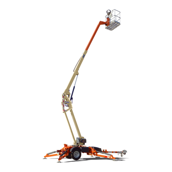
Sign In
Upload
Manuals
Brands
JLG Manuals
Boom Lifts
T350
JLG T350 Manuals
Manuals and User Guides for JLG T350. We have
4
JLG T350 manuals available for free PDF download: Service And Maintenance Manual, Troubleshooting Manual, Operation And Safety Manual, Operating Instructions And Specifications
JLG T350 Service And Maintenance Manual (230 pages)
Brand:
JLG
| Category:
Lifting Systems
| Size: 16.7 MB
Table of Contents
Ageneral
3
Bhydraulic System Safety
3
Maintenance
3
Table of Contents
5
Table no
14
Section 1 - Specifications
15
Capacities
15
Electric Power Unit
15
Electric Power Unit Specifications
15
Operating & Towing Specifications
15
Operating Specifications
15
Tire Specifications
15
Engine
16
Battery
16
Dimensional Data
16
Lubrication
16
Hydraulic Oil
16
Tires
15
Battery Specifications
16
Mobilfluid 424 Specs
16
Major Component Weights
17
Pressure Settings
17
Component Weights
17
Operator Maintenance & Lubrication
18
Lubrication Specifications
18
Figure No.
21
Torque Chart (SAE Fasteners - Sheet 1 of 7)
21
Torque Chart (SAE Fasteners - Sheet 2 of 7)
22
Torque Chart (SAE Fasteners - Sheet 3 of 7)
23
Torque Chart (SAE Fasteners - Sheet 4 of 7)
24
Torque Chart (METRIC Fasteners - Sheet 5 of 7)
25
Torque Chart (METRIC Fasteners - Sheet 6 of 7)
26
Torque Chart (METRIC Fasteners - Sheet 7 of 7)
27
Section 2 - General
29
Machine Preparation, Inspection, and Maintenance
29
General
29
Preparation, Inspection, and Maintenance
29
Pre-Start Inspection
29
Pre-Delivery Inspection and Frequent Inspection
29
Annual Machine Inspection
29
Preventative Maintenance
29
Service and Guidelines
30
General
30
Safety and Workmanship
30
Cleanliness
30
Components Removal and Installation
30
Inspection and Maintenance
30
Component Disassembly and Reassembly
31
Pressure-Fit Parts
31
Bearings
31
Gaskets
31
Bolt Usage and Torque Application
31
Hydraulic Lines and Electrical Wiring
31
Hydraulic System
31
Lubrication
31
Battery
31
Lubrication and Servicing
31
Lubrication and Information
32
Changing Hydraulic Oil
32
Hydraulic Oil
32
Hydraulic System
32
Lubrication Specifications
32
Cylinder Drift Test
33
Cylinder Drift
33
Platform Drift
33
Pins and Composite Bearing Repair Guidelines
33
Welding on JLG Equipment
34
Do NOT Do the Following When Welding on JLG Equipment
34
Do the Following When Welding on JLG Equipment
34
Maintenance Schedule
35
Section 3 - Chassis & Turntable
37
Breaking-In a New Trailer
37
Retighten Lug Nuts at First 10, 25 & 50 Miles
37
Adjust Brake Shoes at First 200 Miles
37
Synchronizing the Brake Systems
37
Trailer Inspection and Service Instructions
37
Fasteners and Frame Members
37
Brake Shoes and Drums
37
Manually Adjusting Brake Shoes
37
Electric Brakes
38
Brake Controller
38
Brake Cleaning and Inspection
38
Shoes and Linings
38
Hydraulic (Surge) Brakes
38
Self Adjusting Mechanism
39
Parking Brake
39
General Maintenance
39
Hubs, Drums, Wheel Bearings
40
Hub Removal
40
Brake Drum Inspection
40
Bearing Inspection
40
Bearing Lubrication
41
Seal Inspection and Replacement
41
Bearing Adjustment
41
Hub and Brake Assembly
42
Tires & Wheels
43
Tire Inflation
43
Tire Replacement
43
Tire Wear
43
Wheel and Tire Replacement
43
Lug Nuts (Bolts)
44
Wheel Installation
44
Wheel Torque Chart - ANSI, ANSI Export, CSA, aus
44
Wheel Torque Chart - CE
44
Spare Tire (Optional)
45
Hydraulic Brake Coupler
46
Troubleshooting
46
Surge Brake Troubleshooting
46
Bleeding the Brake System
47
Towing
47
Backing up
48
Maintenance
49
Extended Storage Instructions
49
Proper Towing Checklist
49
Combination Coupler
50
Bleeding the Brake System
50
General Maintenance
50
Servicing the Emergency Lever
50
Hydraulic Brake Coupler
51
Combination Coupler
52
Hitch Coupler & Axle (CE Only)
53
Ball Coupler
53
Coupling Head Maintenance
55
Damper Maintenance
56
Brake Maintenance
57
Brake Assembly
58
Adjustment and Readjustment of the Overrun Braking System
60
Troubleshooting
62
Malfunctions and Remedies
62
Coupler Assembly (S/N 0030002099 to Present)
63
Engaging Manual Lockout Lever
63
Servicing the Breakaway Assembly
63
Coupler Assembly - S/N 0030002099 to Present
64
Actuator Maintenance
65
Coupler Maintenance
65
Trailer Jack (Solid Wheels)
66
Installation
66
Maintenance
66
Operation
66
Assembly
67
Swing Motor (Prior to S/N 0030000960)
67
Disassembly
67
Removal
67
Assembly
68
Shaft Timing Procedure
69
Installation
70
Swing Motor
71
Swing Motor (S/N 0030001050 to Present)
72
Disassembly and Inspection
72
Removal
72
Swing Drive Motor
73
Assembly
79
One Piece Stator Construction
85
Installation
86
3.14 Swing Bearing
87
Turntable Bearing Mounting Bolt Condition Check
87
Swing Bearing
88
Swing Bearing Removal
89
Wear Tolerance
89
Swing Bearing Installation
90
Swing Bearing Torque Values
91
Swing Drive Checks
91
Swing Bearing Torque Sequence
92
3.15 Engine
93
Throttle & Choke Adjustment
93
Fuel Valve Lever
93
Checking RPM Level
93
Choke Actuator
94
Checking Oil Level
94
Engine Assembly
95
Outrigger Cylinder and Stabilizer
96
Removal
96
Installation
97
Outrigger Assembly
98
3.17 Outrigger Limit Switches
99
Adjustment
99
Procedure for Retracting Outriggers Using Service Harness (Optional)
99
3.19 Leveling, Tilt Sensor Calibration
100
When Machine Is on a Firm Level Surface
100
Setup When Machine Is Not on Firm Level Surface and Adjustment Procedure
101
3.20 Drive & Set
102
Drive & Set Interlocks
103
Drive and Set - Sheet 1 of 2
104
Drive and Set - Sheet 2 of 2
105
3.21 Drive Motor
107
Disassembly and Inspection
107
Assembly
110
Assembly
114
One Piece Stator Construction
120
Batteries (Electric Machines)
122
Quarterly Battery Maintenance
122
Battery Cable Routing
125
3.23 Battery Charger
126
Removal
126
Cover Removal
126
Transformer Replacement
126
Printed Circuit Board Replacement
127
Shunt Assembly Replacement
127
Interlock Relay Replacement
127
SCR Rectifier Replacement (Either Side)
127
AC Circuit Breaker Replacement
128
DC Circuit Breaker Replacement
128
Battery Charger
129
3.24 Battery Charger
131
Operating Instructions
131
Maintenance Instructions
131
Battery Charger Fault Codes
131
Battery Charger Fault Codes (Delta-Q)
131
Section 4 - Boom & Platform
133
Boom and Cylinder Assembly
133
Removal
133
Installation
133
Main Boom
134
Removal
134
Disassembly
134
Assembly
136
Installation
138
Master Cylinder
139
Removal
139
Installation
139
Slave Cylinder
140
Removal
140
Installation
140
Boom and Cylinders Assembly
141
Boom Sensors
142
Boom Elevation Limit Switch
142
Section 5 - Hydraulics
143
Lubricating O-Rings in the Hydraulic System
143
Cup and Brush
143
Dip Method
144
Spray Method
144
Brush-On Method
144
Cylinder Repair
145
Disassembly
145
Inspection
145
Level Cylinder
146
Lift Cylinder
147
Master Cylinder
148
Outrigger Cylinder
149
Telescope Cylinder
150
Assembly
151
Testing
151
5.3 Pressure Setting Procedure
152
Main Relief
152
Platform Level down
152
Platform Level up
152
Swing Left
152
Swing Right
152
Telescope in
152
Telescope out
152
Hydraulic Test Ports
153
Outrigger up
154
Hydraulic Oil Fill at Startup
154
Hydraulic Hoses
154
Hydraulic Filter and Breather
154
Control Valve Torque Values - Sheet 1 of 2
155
Control Valve Torque Values - Sheet 2 of 2
156
Drive Directional Valve Identification - Drive & Set Option
157
Drive Directional Valve Torque Values - Drive & Set Option
158
Drive Enable Valve Identification - Drive & Set Option
159
Hydraulic Diagram
160
Section 6 - Jlg Control System
161
6.1 Introduction
161
To Connect the JLG Control System Analyzer
162
6.3 Using the Analyzer
162
Changing the Access Level of the Hand Held Analyzer
163
Adjusting Parameters Using the Hand Held Analyzer
164
6.6 Machine Setup
165
6.7 System Test
169
Platform Test
169
Ground Test
171
User Fault Codes
172
Ground Module - Sheet 1 of 5
174
Ground Module - Sheet 2 of 5
175
Ground Module - Sheet 3 of 5
176
Ground Module - Sheet 4 of 5
177
Ground Module - Sheet 5 of 5
178
Machine Model Adjustments and Speeds - ANSI & CSA
179
Machine Model Adjustments and Speeds - CE Only
181
Machine Orientation When Setting Speeds
183
Test Notes
183
Machine Configuration Programming Information
184
Help Messages
186
Section 7 - Basic Electrical Information & Schematics
197
General
197
7.2 Multimeter Basics
197
Grounding
197
Backprobing
197
Min/Max
197
Polarity
197
Scale
197
Voltage Measurement
197
Resistance Measurement
198
Continuity Measurement
198
Current Measurement
199
7.3 Checking Switches
199
Basic Check
199
Limit Switches
199
Automatic Switches
200
Switch Wiring - Low Side, High Side
200
Applying Silicone Dielectric Compound to Electrical Connections
200
AMP Connector
201
Applying Silicone Dielectric Compound to AMP Connectors
201
Assembly
201
Connector Assembly Figure 2
202
Disassembly
203
Wedge Lock
203
Service - Voltage Reading
203
Connector Installation
204
7.6 Deutsch Connectors
205
DT/DTP Series Assembly
205
DT/DTP Series Disassembly
205
HD30/HDP20 Series Assembly
206
HD30/HDP20 Series Disassembly
206
Chassis Wiring Harness and Connectors - Sheet 1 of 2
208
Chassis Wiring Harness and Connectors - Sheet 2 of 2
209
Controller and Valve Body Connector Locations
210
Connector Identification
211
Electrical Schematic (Boom Operations) - Sheet 1 of 2
214
Electrical Schematic (Boom Operations) - Sheet 2 of 2
215
Electrical Schematic (Trailer) - Sheet 1 of 3
216
Electrical Schematic (Trailer) - Sheet 2 of 3
217
Electrical Schematic (Trailer) - Sheet 3 of 3
218
Hydraulic Schematic - Electric Machines - Sheet 1 of 2
220
Hydraulic Schematic - Electric Machines - Sheet 2 of 2
221
Hydraulic Schematic - Gas Machines - Sheet 1 of 2
222
Hydraulic Schematic - Gas Machines - Sheet 2 of 2
223
Hydraulic Schematic - Drive Option (Gas) - Sheet 1 of 2
224
Hydraulic Schematic - Drive Option (Gas) - Sheet 2 of 2
225
Hydraulic Schematic - Drive Option (Electric) - Sheet 1 of 2
226
Hydraulic Schematic - Drive Option (Electric) - Sheet 2 of 2
227
Advertisement
JLG T350 Troubleshooting Manual (225 pages)
Brand:
JLG
| Category:
Boom Lifts
| Size: 10.77 MB
Table of Contents
Safety
19
Section A. Introduction
5
Reading Fault Codes
6
Visual Inspection
6
Connector References
6
User Fault Codes
7
User Fault Code Cross References
8
Service Fault Code Cross References
11
Power Module Flash Codes
14
Ground Reference
14
Control Module Power
15
Tilt
16
Critical Vehicle Interlock Scenarios
16
Outriggers
16
General
17
Hydraulic System Safety
17
Troubleshooting Safety
17
Table of Contents
19
Table of Contents
26
All Functions Inoperative
29
Pump Motor will Not Operate - DC Powered Models
29
Section 1 - Troubleshooting by Function
29
All Functions Inoperative, Engine Starts and Runs - Engine Models
30
All Functions Inoperative, Pump Motor Runs - DC Powered Models
30
Battery Charger Not Functioning Properly
31
Engine will Not Crank - Engine Models
32
Engine Cranks but will Not Start - Engine Models
33
Engine High Idle Inoperative - Engine Models
33
Engine Low Idle Inoperative - Engine Models
33
Ground Controls Inoperative
34
Ground Leveling Not Functioning Properly
34
Platform Controls Inoperative
34
Lift down Function Inoperative
35
Lift up Function Inoperative
35
Telescope in Function Inoperative
36
Telescope out Function Inoperative
36
Swing Left Function Inoperative
37
Swing Right Function Inoperative
37
Platform Leveling up Function Inoperative
38
Platform Leveling down Function Inoperative
39
Jib down Function Inoperative
40
Jib up Function Inoperative
40
Outrigger Set Function Inoperative
40
Outrigger Stow Function Inoperative
40
Accessory Fault
41
Battery Voltage too High - System Shutdown
41
Battery Voltage too Low - System Shutdown
41
Section 2 - Troubleshooting by Fault Messages
41
Battery Voltage too Low - System Shutdown
42
CANBUS Failure - Accessory Module Communications Lost
42
CANBUS Failure - Drive Module
43
CANBUS Failure - Platform Module
44
CANBUS Failure - Power Module
45
Chassis Tilt Sensor Gain Not Calibrated
45
Chassis Tilt Sensor Gain out of Range
45
Chassis Tilt Sensor Not Calibrated
46
Chassis Tilt Sensor out of Range
46
Choke Hold Solenoid Open Circuit
47
Choke Hold Solenoid Short to Battery
47
Choke Hold Solenoid Short to Ground
48
Choke Pull Relay Open Circuit
48
Choke Pull Relay Short to Battery
49
Choke Pull Relay Short to Ground
49
Drive & O/R Prevented - Operate from Platform
50
Drive & O/R Prevented - Place Boom on Rest
51
Drive & O/R Prevented - Set Hand Brake
51
Drive Enable Solenoid Short to Battery
51
Drive Enable Solenoid Short to Ground or Open Circuit
52
Drive Left Forward Solenoid Open Circuit
52
Drive Left Forward Solenoid Short to Battery
53
Drive Left Forward Solenoid Short to Ground
53
Drive Left Reverse Solenoid Open Circuit
54
Drive Left Reverse Solenoid Short to Battery
54
Drive Left Reverse Solenoid Short to Ground
55
Drive Prevented - Lift down
55
Drive Prevented - Stow Outriggers
55
Drive Prevented - Telescope in
55
Drive Right Forward Solenoid Open Circuit
56
Drive Right Forward Solenoid Short to Battery
56
Drive Right Forward Solenoid Short to Ground
57
Drive Right Reverse Solenoid Open Circuit
57
Drive Right Reverse Solenoid Short to Battery
58
Drive Right Reverse Solenoid Short to Ground
58
Dump Solenoid Open Circuit
59
Dump Solenoid Short to Battery
59
Dump Solenoid Short to Ground
60
EEPROM Failure - Check All Settings
60
Engine Not Running
60
Extend O/R Solenoid Open Circuit
61
Extend O/R Solenoid Short to Battery
61
Extend O/R Solenoid Short to Ground
62
Front-Left O/R Solenoid Open Circuit
62
Front-Left O/R Solenoid Short to Battery
63
Front-Left O/R Solenoid Short to Ground
63
Front-Right O/R Solenoid Open Circuit
64
Front-Right O/R Solenoid Short to Battery
64
Front-Right O/R Solenoid Short to Ground
65
Function Locked out - Joystick Not Centered at Startup
65
Function Locked out - Trigger Permanently Closed
66
Function Problem - Engine Choke Permanently Selected
66
Function Problem - Engine Choke Permanently Selected
67
Function Problem - Engine Start Permanently Selected
67
Function Problem - Engine Start Permanently Selected
68
Function Problem - Jib down Permanently Selected
68
Function Problem - Jib up and down both Selected
69
Function Problem - Jib up Permanently Selected
69
Function Problem - Level down Permanently Selected
70
Function Problem - Level up and down both Selected
70
Function Problem - Level up Permanently Selected
71
Function Problem - Lift down Permanently Selected
71
Function Problem - Lift up and down both Selected
72
Function Problem - Lift up Permanently Selected
72
Function Problem - Outrigger Set and Stow both Selected
73
Function Problem - Outrigger Set Permanently Selected
73
Function Problem - Outrigger Stow Permanently Selected
74
Function Problem - Rotary Selector Switch
74
Function Problem - Swing Left and Right both Selected
75
Function Problem - Swing Left Permanently Selected
76
Function Problem - Swing Right Permanently Selected
76
Function Problem - Telescope in and out both Selected
77
Function Problem - Telescope in Permanently Selected
77
Function Problem - Telescope out Permanently Selected
78
Functions at Cutback - Power Module Current Limit
78
Functions Locked out - Constant Data Version Improper
78
Functions Locked out - Platform Module Software Version Improper
78
Functions Locked out - Power Module Software Version Improper
79
Ground Alarm Short to Battery
79
Ground Alarm Short to Ground
79
Ground Module Failure: Ref Voltage out of Range
80
Ground Module Failure: Vlow Fet Failure
80
Hourmeter Short to Battery
80
Jib down Solenoid Open Circuit
80
Jib down Solenoid Short to Battery
81
Jib down Solenoid Short to Ground
81
Jib up Solenoid Open Circuit
82
Jib up Solenoid Short to Battery
82
Jib up Solenoid Short to Ground
83
Joystick Faulty - X Axis Wiper out of Range
83
Joystick Faulty - y Axis Wiper out of Range
84
Joystick Moved but Trigger Switch Open
85
Keyswitch Faulty
86
Level down Solenoid Open Circuit
87
Level down Solenoid Short to Battery
87
Level down Solenoid Short to Ground
88
Level up Solenoid Open Circuit
88
Level up Solenoid Short to Battery
89
Level up Solenoid Short to Ground
89
Lift down Prevented - Tele in First
90
Lift down Solenoid Open Circuit
90
Lift down Solenoid Short to Battery
91
Lift down Solenoid Short to Ground
91
Lift up & Tele out Prevented - Tilted & above Elevation
91
Lift up & Tele out Prevented - Tilted,Unset,& above Elevation
92
Lift up & Tele out Prevented - Unset & above Elevation
92
Lift up Prevented - Check Outriggers
92
Lift up Prevented - Lift down then Set Outriggers
93
Lift up Prevented - Tilted
93
Lift up Solenoid Open Circuit
94
Lift up Solenoid Short to Battery
94
Lift up Solenoid Short to Ground
95
Model Changed - Hydraulics Suspended - Cycle EMS
95
No Charge System Output
95
Open-Circuit Pump Motor Wiring
96
Optional Ground Alarm Short to Battery
96
Optional Ground Alarm Short to Ground
96
Outrigger Stow Prevented - Tele in First
97
Outriggers Prevented - Elevated
97
Platform Position Detection Faulty
97
Power Module Failure: Check Power Circuits or Mosfet Short Circuit
98
Power Module Failure: Internal Error
98
Power Module Failure: Personality Range Error
99
Power Module too Hot - Please Wait
99
Rear-Left O/R Solenoid Open Circuit
99
Rear-Left O/R Solenoid Short to Battery
100
Rear-Left O/R Solenoid Short to Ground
100
Rear-Right O/R Solenoid Open Circuit
101
Rear-Right O/R Solenoid Short to Battery
101
Rear-Right O/R Solenoid Short to Ground
102
Retract O/R Solenoid Open Circuit
102
Retract O/R Solenoid Short to Battery
103
Retract O/R Solenoid Short to Ground
103
Running at Creep - Material Hook Mode
104
Running at Creep - Tilted & above Elevation
104
Running at Creep - Unset & above Elevation
104
Start Solenoid Open Circuit
105
Start Solenoid Short to Battery
105
Start Solenoid Short to Ground
106
Swing Left Solenoid Open Circuit
106
Swing Left Solenoid Short to Battery
107
Swing Left Solenoid Short to Ground
107
Swing Right Solenoid Open Circuit
108
Swing Right Solenoid Short to Battery
108
Swing Right Solenoid Short to Ground
109
Tele out Prevented - Set Outriggers
109
Tele out Prevented - Tilted
109
Telescope in Solenoid Open Circuit
110
Telescope in Solenoid Short to Battery
110
Telescope in Solenoid Short to Ground
111
Telescope out Solenoid Open Circuit
112
Telescope out Solenoid Short to Battery
112
Telescope out Solenoid Short to Ground
113
Throttle Hold Solenoid Open Circuit
113
Throttle Hold Solenoid Short to Battery
114
Throttle Hold Solenoid Short to Ground
114
Throttle Pull Relay Open Circuit
115
Throttle Pull Relay Short to Battery
115
Throttle Pull Relay Short to Ground
116
Trigger Closed too Long While in Neutral
116
DC Powered Machine - Hydraulic Pump
117
DC Powered Machine - Power
117
DC Powered Machine - Power Module
117
Section 3 - Component Checks
117
Drive Module - Power
120
Drive Sensor Reset
120
Engine Powered Machine - Hydraulic Pump
122
Engine Powered Machine - Power
122
Ground Module - Power
122
Ignition Relay - Power
123
Joystick Diagnostics
124
Outrigger Switches - All Set
124
Outrigger Switches - All Stowed
125
Platform Module - Power
126
Power Module - Power
126
R-R Outrigger Valve Short to Battery
152
R-R Outrigger Valve Short to Ground
152
Running
152
Start Cl
152
Start Solenoid
153
Start Solenoid Open Circuit
153
Start Solenoid Short to Battery
153
Start Solenoid Short to Ground
153
Start Switch Cl
153
Swing Left Cl
153
Swing Left Valve Open Circuit
153
Swing Left Valve Short to Battery
153
Swing Left Valve Short to Ground
154
Swing Lt Valve
154
Swing Right Cl
154
Swing Right Valve Open Circuit
154
Swing Right Valve Short to Battery
154
Swing Right Valve Short to Ground
154
Swing Rt Valve
154
System Distress Lamp on
154
Tele in Cl
155
Tele in Valve
155
Tele out Cl
155
Tele out Valve
155
Telescope in Valve Open Circuit
155
Telescope in Valve Short to Battery
155
Telescope in Valve Short to Ground
155
Telescope out Valve Open Circuit
155
Telescope out Valve Short to Battery
155
Telescope out Valve Short to Ground
155
Tests Complete
156
Throttle Hold
156
Throttle Hold Solenoid Open Circuit
156
Throttle Hold Solenoid Short to Battery
156
Throttle Hold Solenoid Short to Ground
156
Throttle Pull
156
Throttle Pull Relay Open Circuit
156
Throttle Pull Relay Short to Battery
156
Throttle Pull Relay Short to Ground
157
Tilt Lamp on
157
Section 6 - Calibration Messages
159
Section 7 - Electrical Reference
161
Connector Index
166
Ground Module Connector Pinouts
169
Platform Module Connector Pinout
174
Drive Module Connector Pinout
175
Connector Loading Diagrams
176
Working with AMP Connectors
181
Working with Deutsch Connectors
186
Trailer Wiring
188
Section 8 - Hydraulic References
190
Minimum Operating Pressure
191
Solenoids
191
Hydraulic Schematic - Electric Powered Machines (Sheet 2 of 2)
193
Hydraulic Schematic - Engine Powered Machines (Sheet 1 of 2)
195
Hydraulic Schematic - Engine Powered Machines (Sheet 2 of 2)
196
Hydraulic Schematic - Engine Powered Drive Option (Sheet 1 of 2)
197
Hydraulic Schematic - Engine Powered Drive Option (Sheet 2 of 2)
198
Hydraulic Schematic - Electric Powered Drive Option (Sheet 1 of 2)
199
Hydraulic Schematic - Electric Powered Drive Option (Sheet 2 of 2)
200
Introduction
202
Section 9. Jlg Analyzer
202
To Connect the JLG Control System Analyzer
203
Using the Analyzer
203
Changing the Access Level of the Hand Held Analyzer
204
Hand Held Analyzer
204
Adjusting Parameters Using the Hand Held Analyzer
205
Machine Setup
206
System Test
210
User Fault Codes
212
Introduction
214
Section 10 - Multimeter Basics
214
Voltage Measurement (DC)
214
Resistance Measurement
215
Introduction
218
Operating Specifications
218
Section 11 - Specifications
218
Dimensional Data
219
Electric Power Unit Specifications
219
Light Bulb Information
220
Hydraulic Oil
222
JLG T350 Operation And Safety Manual (132 pages)
Brand:
JLG
| Category:
Boom Lifts
| Size: 4.37 MB
Table of Contents
Table of Contents
7
Section - Paragraph, Subject Page Section - Paragraph, Subject Page
11
Section 1. Safety
13
General
13
Operator Training and Knowledge
13
Towing Regulations
14
Before Operating the Lift
14
Workplace Inspection
14
Machine Inspection
14
Operation
15
General
15
Trip and Fall Hazards
16
Electrocution Hazards
17
Tipping Hazards
19
Crushing and Collision Hazards
20
Lifting, and Hauling
21
Towing Hazards
21
Additional Hazards / Safety
21
Section 2. User Responsibilities, Machine Preparation, and Inspection
23
2.1 Personnel Training
23
Operator Training
23
Training Supervision
23
Operator Responsibility
23
2.2 Preparation, Inspection, and Maintenance
24
Inspection and Maintenance Table
25
Pre-Start Inspection
26
JLG Lift
26
Function Check
27
Basic Nomenclature
28
Daily Walk-Around Inspection - Sheet 1 of 3
30
Daily Walk-Around Inspection - Sheet 2 of 3
31
General
32
Daily Walk-Around Inspection - Sheet 3 of 3
32
Section 3 - Towing
33
General Towing Information
33
Coupler
33
Tow Vehicle and Hitch Information
33
Towing Hitch
33
Coupling and Uncoupling the Trailer
33
Before Coupling the Trailer to Tow Vehicle
33
Tongue Height
34
Coupler and Ball
34
Tongue Jack
34
Coupling the Trailer to the Hitch
35
Uncoupling the Trailer from the Hitch
35
Rigging Safety Chains (if Equipped)
36
Testing Breakaway Brake
36
Connect the Electrical Cables
38
Section - Paragraph, Subject
39
Engaging Manual Lockout Lever
39
Trailer Maneuvering
39
Towing Guidelines
39
Pre-Tow Inspection
41
Pre-Tow Inspection - Sheet 1 of 2
42
Pre-Tow Inspection - Sheet 2 of 2
43
Section 4 - Machine Controls and Indicators
45
General
45
Controls and Indicators
45
Ground Control Station
46
Ground Control Station
47
Platform Station
49
Platform Control Console - Standard Machine
51
Platform Control Console W/Drive & Set Option
52
Section 5 - Machine Operation
55
Description
55
Boom Operating Characteristics and Limitations
55
Capacities
55
Stability
55
Position of Least Forward Stability (T350)
56
Position of Least Forward Stability (T500J)
58
Engine Operation (if Equipped)
60
Starting Procedure
60
Shutdown Procedure
60
Fuel Valve Lever
61
Outriggers
61
From the Ground Console
61
From the Platform Console (Drive & Set Only)
62
Platform
62
Platform Level Adjustment
62
Platform Rotation (if Equipped)
62
Boom
62
Swinging the Boom
63
Raising and Lowering the Boom
63
Telescoping the Boom
63
Jib Lift
64
User Fault Codes
64
Battery Charging
66
Generator Plug Location
67
Battery Charger Fault Codes
68
Platform Removal & Installation
69
Material Hook Installation
70
Material Hook Operating Precautions
71
Accessory Tray
72
Panel Tray
72
Panel Tray
73
Drive & Set
74
To Set up the Machine for Drive & Set Operation
74
Grade and Sideslope
76
To Prepare the Machine for Towing after Drive & Set
77
Operation
77
Shut down and Park
80
Tie down
81
Lifting and Tie down Chart Prior to S/N 0030000864
82
Lifting and Tie down Chart S/N 0030000864 to
83
Present
83
Decal Location - ANSI (Sheet 1 of 2)
84
Decal Location - ANSI (Sheet 2 of 2)
85
Decal Legend (ANSI)
86
Decal Location - CE & Australia (Sheet 1 of 2)
88
Decal Location - CE & Australia (Sheet 2 of 2)
89
Decal Legend - CE & Australia
90
Decal Location - Country Specs (Sheet 1 of 2)
92
Decal Location - Country Specs (Sheet 2 of 2)
93
Decal Legend - Country Specs
94
Section 6 - Emergency Procedures
99
General
99
Incident Notification
99
Emergency Operation
99
Operator Unable to Control Machine
99
Platform or Boom Caught Overhead
100
Manual Descent
100
Lift down
101
Telescope in
102
Telescope out
102
Swing
103
Platform Jib
103
Section 7 - General Specifications & Operator Maintenance
105
Introduction
105
Operating Specifications
105
Dimensional Data
107
Fluid Capacities
107
Electric Power Unit
107
Taillight and Marker Light Bulb Information
108
Tires
108
Engine
109
Batteries (Electric Machines)
109
Component Weights
110
Lubrication
111
Operator Maintenance & Lubrication Diagram
112
Operator Maintenance
113
Tires & Wheels
119
Glossary of Tire and Loading Terminology
119
Basic Tire Maintenance
119
Tire Inflation
120
Tire Wear
120
Tire Repair
121
Tire Replacement
121
Tire Fundamentals
121
Wheel Replacement
124
Wheel Installation
124
Lug Nuts (Bolts)
125
Unsealed Wheel Bearings (Hubs)
126
Supplemental Information
126
Section 8. Inspection and Repair Log
127
Advertisement
JLG T350 Operating Instructions And Specifications (2 pages)
BUCKET LIFT
Brand:
JLG
| Category:
Lifting Systems
| Size: 0.18 MB
Advertisement
Related Products
JLG T500J
JLG TOUCAN DUO
JLG Power Towers Nano
JLG T 1100 A
JLG T 1100 B
JLG T 1100 C
JLG TH336
JLG TH337
JLG TH406
JLG TH407
JLG Categories
Boom Lifts
Lifting Systems
Scissor Lifts
Construction Equipment
Work Light
More JLG Manuals
Login
Sign In
OR
Sign in with Facebook
Sign in with Google
Upload manual
Upload from disk
Upload from URL