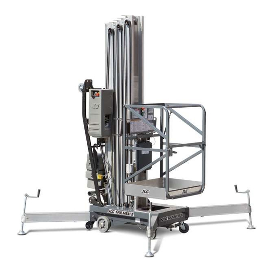
Sign In
Upload
Manuals
Brands
JLG Manuals
Lifting Systems
25AM
JLG 25AM Manuals
Manuals and User Guides for JLG 25AM. We have
5
JLG 25AM manuals available for free PDF download: Operation And Safety Manual, Service And Maintenance Manual
JLG 25AM Operation And Safety Manual (98 pages)
AM Series
Brand:
JLG
| Category:
Lifting Systems
| Size: 3.84 MB
Table of Contents
Table of Contents
7
Section - Paragraph, Subject Page
11
Section 1 - Safety Precautions
11
General
11
Transporting
11
Transport
11
Tipping Hazards
12
Tilt Back Procedure
14
Pre-Operation
15
General
15
Electrocution Hazard
16
Minimum Approach Distance (M.A.D.)
16
Operation
17
Maintenance Safety Precautions
20
Section 2 - User Responsibilities, Machine Preparation, and Inspection
21
Personnel Training
21
Operator Training
21
Training Supervision
21
Operator Responsibility
21
Preparation, Inspection, and Maintenance
22
Inspection and Maintenance Table
23
Pre-Start Inspection
24
Section - Paragraph, Subject Page
25
Function Check
25
Daily Walk-Around Inspection
25
Daily Walk-Around Inspection
27
3.1 General
29
Section 3 - Machine Controls and Indicators
29
3.2 Controls and Indicators
29
Ground Control Station
29
Manual Descent Valve Location
31
Platform Control Station
31
Manual Descent Valve
32
Platform Control Station
32
Decal Installations
33
Decal Installation. (ANSI/CSA) (Machines Prior to S/N-0900031618)
33
Decal Installation Chart (ANSI and CSA)
34
Decal Installation Chart (ANSI and CSA)
35
Decal Installation Chart (CE Specification)
37
Decal Installation Chart (CE Specification)
38
Decal Installation. (ANSI/CSA) (Machines S/N-0900031618 to Present)
39
Section 4 - Machine Operation
45
Description
45
Operating Characteristics and Limitations
45
Capacities
45
Battery Charging & Maintenance
46
Battery Maintenance and Safety
46
Battery Charger Operation
47
Battery Box and Charger Assembly
47
Abnormal Cycle Indicator LED
48
Dual Voltage Charger - Front Panel
48
Machine Set-Up and Operation
49
Caster Brake Operation
49
Setting & Releasing Caster Brake
49
Outrigger Installation
50
Outrigger Installation
51
Platform Loading
52
Platform Operation
52
Maximum Platform Capacity
52
Quick-Change Platform Mounts
53
Platform Removal
53
Quick Change Platform Mount
53
Platform Installation
54
Machine Shut down and Park
54
Transport, Lifting and Tie down
55
General
55
Transporting by Pushing
55
Tilt-Back Assembly Set-Up (AM36/AM41) - Machines Prior to S/N - 0900031618
55
Tilt-Back Assembly Set-Up
56
Tilt-Back Assembly Set-Up (AM36/AM41) - Machines S/N - 0900031618 to Present
59
Tilt-Back Assembly Set-Up - Machines S/N - 0900031618 to Present
60
Tilt-Back Assembly Set-Up - Machines S/N - 0900031618 to Present
61
Tilt-Back Assembly Set-Up - Machines S/N - 0900031618 to Present
62
Pickup Truck Loading Device (Option)
63
Lifting
67
Machine Tie down
67
AM Machine Gross Weights
67
Section - Paragraph, Subject Page
69
Section 5 - Optional Equipment
69
Optional Equipment
69
22" X 25" Quick-Change Platform
69
26" X 26" Quick-Change Platform
69
25" X 26" Step-In Molded Platform
69
W/Swing-Up Gate
69
Tool Tray
69
Fluorescent Tube Caddy
69
Crane Hook
69
Straddle Extension
69
Extra Power Pack (Battery, Charger & Case)
70
Platform Auxiliary Power Lowering Device
70
Laser Positioning Device
70
Hour Meter
70
Machine Cycle Counter Meter
70
Ground Control Station
70
Hour Meter Location. (Option)
70
Am-Se - Straddle Extension - Installation
71
Description
71
Straddle Adaptor Wiring Components
71
Straddle Adaptor Wiring Installation
71
AM-SE - Straddle Extension
71
Section - Paragraph, Subject Page
71
Section - Paragraph, Subject Page
73
SE-Adapter - Wiring - Grommet & Spring Clip
73
(Same for both Sides)
73
Straddle Adapter Wiring Harness to am Wiring
74
Straddle Extension - Components
75
Mounting - Straddle Extension to am
75
Set-Up and Operation
75
Straddle Extension Component Assembly
76
Positioning Straddle Unit and
77
Lowering am Machine on Straddle Unit
78
Straddle and am Machine Disassembly
79
Side Lifting Rail - Quick Release Pins
79
Section 6 - Emergency Procedures
81
General Information
81
Emergency Operation
81
Operator Unable to Control Machine
81
Platform Caught Overhead
81
Righting of Tipped Machine
81
Incident Notification
82
Section - Paragraph, Subject Page
83
Section - 7 - General Specifications and Operator
83
Introduction
83
General Specifications
84
Machine Specifications
84
Electrical Specifications
85
Battery Specifications
85
Platform Data
86
Machine Component Weights
87
Serial Number Locations
87
Operator Maintenance
88
Lubrication Specifications
88
Battery Maintenance
89
Battery Fluid Level
89
Lubrication Intervals for Various Components
91
Supplemental Information
92
Inspection and Repair Log
93
Section 8 - Inspection and Repair Log
94
Advertisement
JLG 25AM Service And Maintenance Manual (84 pages)
Brand:
JLG
| Category:
Scissor Lifts
| Size: 3.75 MB
Table of Contents
Introduction - Operation/Safety Precautions
5
Introduction - Maintenance Safety Precautions
6
General
6
Hydraulic System Safety
6
Maintenance Safety
6
Effectivity Changes
7
Table of Contents
9
Section 1 - Specifications
13
Capacities
13
Hydraulic Oil Reservoir
13
Component Data
13
Hydraulic Pump/Electric Motor Assembly
13
Batteries (1) - DC Models
13
Battery Charger - DC Models
13
Performance Data
13
Platform Capacity
13
Platform Cycle Performance
13
Machine Height (Platform Stowed)
14
Maximum Platform Height (Mast Extended)
14
Maximum Working Height (Average Person)
14
Machine Overall Width and Length (Base)
14
Outrigger Footprint
14
Outrigger Machine Leveling Capability
14
Torque Requirements
14
Lubrication
14
Hydraulic Oil (HO)
14
Hydraulic Pressure Adjustment
15
Cylinder Specifications
15
Serial Number Locations
15
Hydraulic Pressure Setting - Adjustment Screw Located at Base of Pump Motor
15
Torque Chart
17
Section 2 - Service Procedures
25
Machine Preparation, Inspection, and Maintenance
25
General
25
Preparation, Inspection, and Maintenance
25
Pre-Start Inspection
25
Pre-Delivery Inspection and Frequent Inspection
25
Annual Machine Inspection
25
Preventative Maintenance
25
Preventive Maintenance and Inspection Schedule
26
Servicing and Maintenance Guidelines
29
General
29
Safety and Workmanship
29
Cleanliness
29
Components Removal and Installation
29
Component Disassembly and Reassembly
29
Pressure-Fit Parts
29
Bearings
29
Gaskets
29
Bolt Usage and Torque Application
30
Hydraulic Lines and Electrical Wiring
30
Hydraulic System
30
Lubrication and Servicing
30
Batteries
30
Mast Chain Inspection Procedure
30
Mast Cable Inspection Procedure
31
Lubrication Information
32
Hydraulic System
32
Hydraulic Oil
32
Changing Hydraulic Oil
32
Lubrication Specifications
32
Battery Charger - Assembly and Disassembly
33
General Information
33
Battery Charger Removal
33
Cover Removal
33
Transformer Replacement
34
Printed Circuit Board Replacement
34
DC Circuit Breaker Replacement
34
AC Circuit Breaker and Voltage Selection Switch Replacement
35
Shunt Assembly, Varistor, and SCR Rectifier Replacement (See Illustration)
35
Hydraulic Lift Pump - Servicing
36
FENNER BRAND PUMP - Brush Replacement
36
Motor Cap/Motor Installation
36
Motor Brush Installation
36
Brush Housing Final Assembly Tips
37
MONARCH BRAND PUMP - Brush Replacement
38
Motor Assembly - Remove/Install - Reference Marks
38
Motor/Brush Cover - Remove/Install
38
Brush Carrier Assembly - Remove/Install
39
Brush Assembly - Remove/Install
39
TANK and PUMP REMOVAL - (All Pumps)
40
Tank Installation
40
Filter Screen Installation
40
Pump Installation
40
Pressure Adjust Valve Installation
41
Pressure Check Valve Installation
41
Hydraulic Lift Cylinder - Removal, Inspection and Rebuild
42
Cylinder Removal
42
Cylinder Disassembly
42
Lift Cylinder Component Inspection
42
Lift Cylinder Internal Component Assembly Cross-Section
43
Cylinder Assembly
44
Installation
44
Mast Assembly and Disassembly Procedures
45
Mast Disassembly Procedure
45
Mast Section - Assembly/Disassembly Reference
45
Platform Section Removal (All Masts)
46
Mast Section 6 Removal (7 Section Mast)
46
Mast Section 5 Removal (6 & 7 Section Mast)
46
Mast Section 4 Removal (All Masts)
46
Mast Section 3 Removal (All Masts)
47
Mast Section 2 Removal (All Masts)
47
Mast Section 1 Disassembly (All Masts)
47
Mast Assembly
48
Mast Section 1 - Assembly (All Masts)
48
Mast Section 2 - Assembly (All Masts)
48
20AM Mast Assembly Components. (5 - Section)
49
25AM & 36AM Mast Assembly Components. (6 - Section)
50
30AM & 41AM Mast Assembly Components. (7 - Section)
51
Mast Chain/Cable Routing Diagram
52
Mast Section 3 - Assembly (All Masts)
53
Mast Section 4 - Assembly (All Masts)
54
Mast Section 5 - Assembly (25/30/36/41 Ft. Masts)
55
Mast Section 6 - Assembly (30/41 Ft. Masts)
56
Platform Mounting Section - Assy. (All Masts)
56
Mast to Base Frame Installation
58
Mast Chains/Cables and Sequencing Cables Adjustment
59
Mast Chain/Cable Adjustment
59
Mast Chain/Cable/Sequence Cable Adjustment Components. (Typical)
59
Sequencing Cable Adjustment
60
Sequence Cable Replacement Kit
61
Remove Old Cable
61
Replacement Cable Installation
61
Clamp Installation (Drum/Socket Type)
61
Section 3 - Troubleshooting
63
General
63
Troubleshooting Information
63
Hydraulic Circuit Checks
63
Electrical System - Multimeter Basics
63
Grounding
63
Backprobing
63
Min/Max
63
Polarity
64
Scale
64
Continuity Measurement over Long Distances
64
Requirements
64
Procedure
64
Continuity Measurement
64
Resistance Measurement
65
Electrical Switch Testing
67
Basic Check
67
Limit Switches
67
Automatic Switches
67
Switch Wiring - Low Side, High Side
67
Outrigger Interlock Contacts
70
Outrigger Socket and Outrigger Beam - Interlock Contacts
70
Outrigger Socket - Contactor Screw Mounting Instructions
70
Outrigger Beam - Interlock Contactor Plate Mounting Instructions
70
Outrigger Socket Contactor Heads and Outrigger Beam - Contactor Plate Mounting Hardware (ORIGINAL and 5/2001 - DESIGN)
71
Detent Screws
72
Hydraulic Schematic. (am Series) (2792491_A)
73
Electrical Diagram. (am Series - 12V-DC)
74
JLG 25AM Service And Maintenance Manual (93 pages)
Brand:
JLG
| Category:
Forklifts
| Size: 4.78 MB
Table of Contents
General
3
Bhydraulic System Safety
3
Cmaintenance
3
Table of Contents
5
Table no
10
General Specifications
12
Operating Specifications
12
Machine Specifications
12
Electrical Specifications
12
Battery Specifications
12
Performance Data
13
Platform Data
13
Machine Component Weights
13
Serial Number Plate Locations
13
Torque Requirements
13
Lubrication
13
Hydraulic Oil (HO)
13
Hydraulic Oil Operating Range
13
Lubrication Specifications
14
Lubricant Key
14
Model am - Lubrication Intervals for Various Components
14
Battery Maintenance
15
Hydraulic Pressure Adjustment
15
Cylinder Specifications
16
Threadlocking Compound
17
Torque Charts
18
SAE Fastener Torque Chart
18
Metric Fastener Torque Chart
24
Service Procedures
29
Machine Preparation, Inspection, and Maintenance
29
General
29
Preparation, Inspection, and Maintenance
29
Pre-Start Inspection
29
Pre-Delivery Inspection and Frequent Inspection
29
Annual Machine Inspection
29
Preventative Maintenance
29
Preventive Maintenance and Inspection Schedule
30
Maintenance and Inspection Schedule Codes
30
Footnotes
30
Inspection and Maintenance
30
AM Model - Preventive Maintenance & Inspection Schedule
31
Servicing and Maintenance Guidelines
33
General
33
Safety and Workmanship
33
Cleanliness
33
Components Removal and Installation
33
Component Disassembly and Reassembly
33
Pressure-Fit Parts
33
Bearings
33
Gaskets
33
Bolt Usage and Torque Application
33
Lubrication and Servicing
34
Batteries
34
Mast Chain Inspection Procedure
34
Chain Stretch Tolerance
34
Lubrication Information
35
Hydraulic System
35
Hydraulic Oil
35
Changing Hydraulic Oil
35
Lubrication Specifications
35
Battery Charger - Assembly and Disassembly
36
General Information
36
Battery Charger Removal
36
Cover Removal
36
Transformer Replacement
37
Printed Circuit Board Replacement
37
DC Circuit Breaker Replacement
37
AC Circuit Breaker and Voltage Selection Switch Replacement
38
Shunt Assembly, Varistor, and SCR Rectifier Replacement (See Illustration)
38
Fuse Replacement
39
Bucher Brand Pump - Brush Replacement
40
Motor Assembly - Remove/Install - Reference Marks
40
Motor/Brush Cover - Remove/Install
40
Brush Carrier Assembly - Remove/Install
41
Brush Assembly - Remove/Install
41
Tank and Pump Removal - (All Pumps)
42
Tank Installation
42
Filter Screen Installation
42
Pump Installation
42
Pressure Adjust Valve Installation
43
Pressure Check Valve Installation
43
Hydraulic Lift Cylinder - Removal, Inspection and Rebuild
44
Cylinder Removal
44
Cylinder Disassembly
44
Lift Cylinder Component Inspection
44
Cylinder Assembly
47
Installation
47
Mast Disassembly Procedure
48
AM Series Mast Component Features
48
Platform Section Removal (All Masts)
49
Mast Section 6 Removal (7 Section Mast)
49
Mast Section 5 Removal (6 & 7 Section Mast)
49
Mast Section 4 Removal (All Masts)
49
Mast Section 3 Removal (All Masts)
49
Mast Section 2 Removal (All Masts)
50
Mast Section 1 Disassembly (All Masts)
50
Mast Assembly
50
Mast Section 1 - Assembly (All Masts)
50
Mast Section 2 - Assembly (All Masts)
50
Mast Section 3 - Assembly (All Masts)
54
Mast Section 4 - Assembly (All Masts)
55
Mast Section 5 - Assembly (All Masts)
56
Mast Section 6 - Assembly (25 Ft. Masts)
56
Mast to Base Frame Installation
59
Mast Chains/Cables and Sequencing Cables Adjustment
60
Mast Chain/Cable Adjustment
60
Sequencing Cable Adjustment
61
Sequence Cable Replacement Kit
61
Remove Old Cable
61
Replacement Cable Installation
61
Clamp Installation (Drum/Socket Type)
61
Load Sensing System (LSS)
64
Setting Spring Pre-Load
65
Setting Positive Stops
65
Adjusting Switch
65
Troubleshooting
68
General
68
Troubleshooting Information
68
Hydraulic Circuit Checks
68
Electrical System - Multimeter Basics
68
Grounding
68
Backprobing
68
Min/Max
68
Polarity
69
Scale
69
Continuity Measurement over Long Distances
69
Requirements
69
Procedure
69
Electrical Switch Testing
72
Basic Check
72
Limit Switches
72
Automatic Switches
72
Switch Wiring - Low Side, High Side
72
AC Unit - Troubleshooting
73
DC Unit - Troubleshooting
74
Outrigger Interlock Contacts
75
Outrigger Socket and Outrigger Beam - Interlock Contacts
75
Outrigger Socket - Contactor Screw Mounting Instructions
75
Outrigger Beam - Interlock Contactor Plate Mounting Instructions
75
Detent Screws
77
Hydraulic Schematic
79
Electric Schematic
80
Advertisement
JLG 25AM Operation And Safety Manual (78 pages)
Brand:
JLG
| Category:
Lifting Systems
| Size: 5.64 MB
Table of Contents
Contact
6
In USA
6
Outside USA
6
Table of Contents
8
Section - - Revision Log
12
Section 1 - Safety Precautions
12
General
12
Transporting
12
Transport
12
Tipping Hazards
13
Tilt Back Procedure
15
Pre-Operation
16
General
16
Electrocution Hazard
17
Minimum Approach Distance (M.A.D.)
17
Operation
18
Maintenance Safety Precautions
21
Tion, and Inspection
22
Section - 2 - User Responsibilities, Machine Prepara
22
Personnel Training
22
Operator Training
22
Training Supervision
23
Operator Responsibility
23
Machine Familiarization
23
Preparation, Inspection, and Maintenance
23
Inspection and Maintenance Table
24
Pre-Start Inspection
25
Function Check
26
Daily Walk-Around Inspection
26
Daily Walk-Around Inspection
28
3.1 General
30
Section 3 - Machine Controls and Indicators
30
3.2 Controls and Indicators
30
Ground Control Station
30
Ground Control Station
31
Manual Descent Valve
32
Platform Control Station
32
Manual Descent Valve Location
32
Platform Control Station
33
Section - Paragraph, Subject Page
34
Decal Installations
34
Decal Installation. (ANSI/CSA)
34
Decal Installation Chart (ANSI and CSA)
35
Decal Installation (CE and AUS)
37
Section 4 - Machine Operation
41
Description
41
Operating Characteristics and Limitations
41
Capacities
41
Battery Charging & Maintenance
42
Only)
42
Battery Maintenance and Safety
42
Battery Fluid Level
42
Battery Charger Operation
43
Abnormal Cycle Indicator LED
44
Machine Set-Up and Operation
45
Caster Brake Operation
45
Outrigger Installation
46
Outrigger Installation
47
Platform Loading
48
Platform Operation
48
Maximum Platform Capacity
48
Quick-Change Platform Mounts
49
Platform Removal
49
Quick Change Platform Mount
49
Platform Installation
50
Machine Shut down and Park
50
Transport, Lifting and Tie down
51
General
51
Transporting by Pushing
51
Tilt-Back Assembly Set-Up (AM38)
52
Tilt-Back Assembly Set-Up
53
Tilt-Back Assembly Set-Up
55
Pickup Truck Loading Device (Option)
56
Lifting
60
Machine Tie down
60
AM Machine Gross Weights
60
Section - 5 - Optional Equipment
61
22" X 22" Quick-Change Platform (Not Available in CE Markets)
61
26" X 26" Quick-Change Platform (Not Available in CE Markets)
61
Tool Tray
61
Fluorescent Tube Caddy
61
Crane Hook
61
Extra Power Pack (Battery, Charger & Case)
61
Platform Auxiliary Power Lowering Device
61
Hour Meter
61
Section - Paragraph, Subject Page
63
Section 6 - Emergency Procedures
63
General Information
63
Emergency Operation
63
Operator Unable to Control Machine
63
Platform Caught Overhead
63
Righting of Tipped Machine
64
Incident Notification
64
Section 7 - General Specifications and Operator Maintenance
65
Introduction
65
General Specifications
66
Machine Specifications
66
Electrical Specifications
67
Battery Specifications
67
Platform Data
68
Machine Component Weights
69
Serial Number Locations
69
Operator Maintenance
70
Lubrication Specifications
70
Battery Maintenance
71
Lubrication Intervals for Various Components
73
Supplemental Information
74
Section 8. Inspection and Repair Log
75
Inspection and Repair Log
75
JLG 25AM Service And Maintenance Manual (62 pages)
Brand:
JLG
| Category:
Scissor Lifts
| Size: 2.45 MB
Table of Contents
Table of Contents
8
Hydraulic Pressure Setting - Adjustment Screw Located at Base of Pump Motor
12
Torque Chart
14
2.4 Lubrication Information
22
Hydraulic System
22
Hydraulic Oil
22
Changing Hydraulic Oil
22
Lubrication Specifications
22
Battery Charger - Assembly and Disassembly
23
General Information
23
Battery Charger Removal
23
Cover Removal
23
Transformer Replacement
24
Printed Circuit Board Replacement
24
DC Circuit Breaker Replacement
24
AC Circuit Breaker and Voltage Selection Switch Replacement
25
Shunt Assembly, Varistor, and SCR Rectifier Replacement (See Illustration)
25
2.6 Hydraulic Lift Pump - Servicing
26
FENNER BRAND PUMP - Brush Replacement
26
Motor Cap/Motor Installation
26
Motor Brush Installation
26
Brush Housing Final Assembly Tips
27
MONARCH BRAND PUMP - Brush Replacement
28
Motor Assembly - Remove/Install - Reference Marks
28
Motor/Brush Cover - Remove/Install
28
Brush Carrier Assembly - Remove/Install
29
Brush Assembly - Remove/Install
29
TANK and PUMP REMOVAL - (All Pumps)
30
Tank Installation
30
Filter Screen Installation
30
Pump Installation
30
Pressure Adjust Valve Installation
31
Pressure Check Valve Installation
31
Hydraulic Lift Cylinder - Removal, Inspection and Rebuild
32
Cylinder Removal
32
Cylinder Disassembly
32
Lift Cylinder Component Inspection
32
Lift Cylinder Internal Component Assembly Cross-Section
33
Cylinder Assembly
34
Installation
34
Mast Assembly and Disassembly Procedures
35
Mast Disassembly Procedure
35
Platform Section Removal
35
Mast Section - Assembly/Disassembly Reference
35
Mast Section 4 Removal
36
Mast Section 3 Removal
36
Mast Section 2 Removal
36
Mast Section 1 Disassembly (All Masts)
36
Mast Assembly
37
Mast Section 1 - Assembly
37
Mast Section 2 - Assembly
37
15SP Mast Assembly Components. (5 Section)
38
12SP Mast Assembly Components. (4 Section)
39
Mast Chain Routing Diagram
40
Mast Section 3 - Assembly
41
Mast Section 4 - Assembly
42
Platform Mounting Section - Assembly
43
2.10 Mast to Base Frame Installation
43
Mast Chains/Cables and Sequencing Cables Adjustment
44
Mast Chain/Cable Adjustment
44
Mast Chain/Cable/Sequence Cable Adjustment Components. (Typical)
45
Sequencing Cable Adjustment
46
2.12 Sequence Cable Replacement Kit
46
Remove Old Cable
46
Replacement Cable Installation
46
Clamp Installation (Drum/Socket Type)
47
Section 3 - Troubleshooting
49
3.1 General
49
3.2 Troubleshooting Information
49
3.3 Hydraulic Circuit Checks
49
Electrical System - Multimeter Basics
49
Grounding
49
Backprobing
49
Min/Max
49
Polarity
50
Scale
50
Continuity Measurement over Long Distances
50
Requirements
50
Procedure
50
Continuity Measurement
50
Resistance Measurement
51
3.5 Electrical Switch Testing
53
Basic Check
53
Limit Switches
53
Automatic Switches
53
Switch Wiring - Low Side, High Side
53
Hydraulic Schematic. (SP Series)
55
Electrical Diagram (Standard)
56
Advertisement
Related Products
JLG 2505H
JLG 2505
JLG 25RTS
JLG 2032ES
JLG 2632ES
JLG 2033E3
JLG 2046E3
JLG 2658E3
JLG 2646E3
JLG 2039ES
JLG Categories
Boom Lifts
Lifting Systems
Scissor Lifts
Construction Equipment
Work Light
More JLG Manuals
Login
Sign In
OR
Sign in with Facebook
Sign in with Google
Upload manual
Upload from disk
Upload from URL