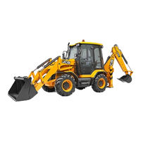
Sign In
Upload
Manuals
Brands
jcb Manuals
Other
3CX
jcb 3CX Manuals
Manuals and User Guides for jcb 3CX. We have
9
jcb 3CX manuals available for free PDF download: Service Manual, Operator's Manual
jcb 3CX Service Manual (891 pages)
Backhoe Loader
Brand:
jcb
| Category:
Other
| Size: 39.2 MB
Table of Contents
Machine Nomenclature
2
Colour Coding
3
Table of Contents
4
Machine Identification Plate
5
Typical Vehicle Identification Number (VIN)
5
Serial Plates
6
Torque Settings
7
Service Tools Numerical List
8
12V Mobile Oven
11
Body & Framework
11
Cartridge Gun
11
Hand Cleaner
11
Service Tools - Body and Framework
11
240V Static Oven
12
Glass Extractor (Handles)
12
Glass Lifter
12
Wire Starter
12
Braided Cutting Wire
13
Long Knife
13
Nylon Spatula
13
Rubber Spacer Blocks
13
AVO Test Kit
14
Battery Tester
14
Service Tools - Electrics
14
Socket for Alternator Pulley Nut
14
Electrical Repair Kit
15
Flow Test Equipment
16
Hydraulic Circuit Pressure Test Kit
16
Pressure Test Adapters
16
Service Tools - Hydraulics
16
Bonded Washers
17
Hand Pump Equipment
17
Male Adapters
17
Valve Spool
17
Female Cone Blanking Plug
18
Female Connectors
18
Male Cone Blanking Cap
18
Piston Seal Assembly Tool
19
Ram Seal Protection Sleeves
19
Replacement Plastic Boss
19
Seal Fitting Tool
19
Bearing Press
20
Drive Coupling Spanner
20
Fitting Tool Assembly
20
Torque Measuring Tool for Wheel Hub Seals
20
Transmission
20
Adapter - Impulse Extractor
21
Impulse Extractor Set for Hub Bearing Seals
21
Measuring Cup
21
Splined Bolt Socket for Driveshafts
21
Bearing Pad Driver
22
Flange Spanner
22
Service Tools - Transmission
22
Torque Multiplier
22
Powershift Gearbox Flow Test Adaptor
23
Synchro Shuttle Gearbox
23
Flow Test Equipment List
24
Hydraulic Circuit Pressure Test Kit - List
24
Solid Spacer Setting Kit
26
Spacer Kit
26
Powershift
27
Speed Sensor Test Harness
27
Thrust Washer Kit
27
Transmission Jack
27
Powershift Gearbox - 6 Speed (Shiftmaster) Electronic Service Tool Kit
28
Adaptor for Compression Testing (AK, AM, AR)
29
De-Glazing Tool for Cylinder Bores
29
Issue
29
Lifting Wire Assembly
29
Service Tools - Engine
29
Sealing and Retaining Compounds
30
Care & Safety
31
Safety Notices
32
General Safety
33
Operating Safety
34
Maintenance Safety
35
Routine Maintenance
38
First Aid - Oil
41
Hygiene
41
Lubricants - Health and Safety
41
Spillage
41
Waste Disposal
41
Pre-Start Cold Checks
42
Service Schedules
42
Functional Test and Final Inspection
44
Loader Arm Safety Strut Installation
45
Loader Arm Safety Strut Removing
45
Checking for Damage
46
Cleaning the Machine
47
Engine Panels
48
Opening and Closing the Bonnet
48
Removing and Fitting a Side Panel
48
Checking the Seat Belt Condition and Security
49
Seat Belt Maintenance
49
Greasing
50
Loader Arms
50
Backhoe & Quickhitch
51
Front Axle (2 Wheel Drive Machines)
52
Front Axle (4 Wheel Drive Machines)
52
Front Axle (All Wheel Steer Machines)
53
Rear Axle (All Wheel Steer Machines)
53
Driveshafts
54
Extending Dipper
54
6 - in - 1 Clamshovel
55
Loader Quickhitch
55
Stabilisers (Centremount Machines)
55
Kingpost
56
Power Sideshift
56
Backhoe Quickhitch (Hydraulic)
57
Knuckle (if Fitted)
57
Checking the Wheel Nut Torques
58
Tyre Inflation
58
Tyres and Wheels Maintenance
58
Brakes Maintenance
59
Checking the Foot Brake Fluid Level
59
Parking Brake Adjustment
59
Changing the Elements
60
Engine Air Filter Maintenance
60
Changing the Oil and Filter
61
Checking the Oil Level
61
Engine Oil and Filter Maintenance
61
Changing the Coolant
62
Checking the Coolant
62
Engine Cooling System Maintenance
62
Adjusting the Fan Belt
63
Cleaning the Cab Heater Filter
63
Advice
64
Fuel Standards
64
Fuel System Maintenance
64
Low Temperature Fuels
64
Petrol
64
Types of Fuel
64
Changing the Filter Element
65
Draining the Filter
65
Filling the Tank
65
Bleed the System
66
Draining the Sediment Bowl
66
Changing the Oil and Filter (Synchro Shuttle) Gearbox
67
Checking the Oil Level (Synchro Shuttle Gearbox)
67
Synchro Shuttle Gearbox Maintenance
67
Checking the Oil Level (Powershift Gearbox)
68
Changing the Oil Filter (Powershift Gearbox)
69
Checking the Fluid Level
70
Hydraulic System Maintenance
70
Hydraulic Tank Cap
70
Changing the Filter Element (Hydraulic System)
71
Changing the Suction Strainer
72
Checking the Differential Oil Level
73
Front and Rear Axle (All Wheel Steer Machines) Maintenance
73
Changing the Hub Oil
74
Checking the Hub Oil Levels
74
Changing the Oil
75
Checking the Oil Level
75
Front and Rear Axle (Two Wheel Steer Machines)
75
Battery Maintenance
76
Battery: Warning Symbols
76
Checking the Electrolyte Level
77
First Aid - Electrolyte
77
Battery Isolator
78
Cleaning the Tubes/Fins
79
Hydraulic Oil Cooler
79
Stabiliser Legs (Sideshift Machines Only)
80
Wear Pad Adjustment
80
Adjusting the Compressor Drive Belt
81
Air Conditioning Maintenance
81
Checking Hose Burst Protection Valve
82
Hose Burst Protection Valve (if Fitted)
82
Lowering a Load
82
Service Capacities and Lubricants
83
Coolant Mixtures
84
Body & Framework
86
Body & Framework: Service Tools
88
Slide Hammer Kit Procedure
91
Rivet Nut Tool Procedure
92
Air Conditioning Data
93
Body and Framework: Technical Data
93
Body & Framework - Basic Operation
94
Air Conditioning
95
R-134A Refrigerant
95
System Operation
95
Air Conditioning
96
Basic Operation
96
System Control
96
System Operation
96
Technical Data Air Conditioning (Option)
96
Safety Procedures (Air Conditioning System)
97
Fault Finding
98
General Fault Indications (Air Conditioning)
98
Sight Glass Indications
98
Fault Finding (Air Conditioning)
99
No Air Conditioning
99
Air Conditioning - System Diagnosis
100
Normally Functioning A/C System
100
Low R-134A Charge
101
Poor Refrigerant Circulation
101
System Diagnosis
101
Insufficient Cooling of Condenser or Refrigerant Overcharge
102
No Refrigerant Circulation
102
Air in System
103
Expansion Valve Improperly M Ounted or Heat Sensing Tube Defective (Opening too Wide)
103
Compressor Malfunction
104
Some Moisture in the System
104
Wiring Continuity Checks
105
Air Conditioning: Service Procedures
106
Checking Refrigerant Charge Level
106
Leak Testing
106
Tightening Leaking Hoses
106
Refrigerant Charging and Discharging
107
Refrigerant Recovery
107
Evacuating (Vacuuming)
108
Electronic Vacuum Gauge
109
Relubricating
110
Refrigerant Charging
111
Binary Pressure Switch Testing
112
Condenser Matrix Cleaning
113
Filters - Changing and Cleaning
114
Compressor Drive Belt - Adjusting
115
Glazing
116
Removing Broken Glass and Old Sealant
116
Preparing the Cab Frame Aperture
118
Preparing the New Glass
119
Installing the New Glass
120
Cab ROPS/FOPS Structure - Checks
122
Engine Panels - Removing and Fitting
123
Stabiliser Leg - Wear Pad Adjustment
124
Stabiliser Legs Wear Pads
124
Extending Dipper - Wear Pad Adjustment
125
Inspecting the Top Wear Pads
125
Adjusting the Bottom Wear Pads
126
Sideshift - Hydraclamp Clearance Setting
127
Power Sideshift - Wear Pad Renewal
128
Power Sideshift - Chain Adjustment
129
Air Conditioning Hvac*/Air Conditioning Unit - Removal and Replacement
131
Freeze Protection Thermostat
131
Blower Unit - Removal and Replacement
133
Evaporator Matrix - Removal and Replacement
133
Freeze Protection Thermostat - Removal and Replacement
133
Binary Pressure Switch - Removal and Replacement
135
Loader Arms Diagram
136
Loader Arms Removal and Replacement
137
Stabiliser Legs Diagram
138
Stabiliser Legs Removal and Replacement - (Centremount Machines)
139
Stabiliser Legs Removal and Replacement (Sideshift Machines)
141
Kingpost Removal and Replacement
142
Boom and Dipper Diagram
144
Boom - Removal and Replacement
145
Dipper - Removal and Replacement
147
Hydraulic Tank Removal and Replacement
148
Power Sideshift Ram Removal and Replacement
149
Cab Panels Removal and Replacement
150
Side Console
150
Front/Steering Console
151
Electrics
152
Electrics - Service Tools
154
Alternator
155
Electrics: General Electrical Data
155
System Type
155
Technical Data
155
Fuses and Relays
156
Link Box Fuses
158
Relays
158
Circuit Schematic - Basic Machine
159
Basic System Operation
160
Circuit Schematic - Powershift
163
Circuit Schematic - Synchro Shuttle
163
2 Wheel Steer/Brake Mode
165
2 Wheel Steer/Brake Mode (Germany)
165
Circuit Schematics - Options
165
Steer Mode - 4CX and 3CX Super (4X4X4)
165
S Mode Schematics
166
Steermode 3CX Super (4X4X4) Schematics
166
All Wheel Steer/Brake Mode Schematics
167
Auxiliary and Hydraclamp Hydraulics Schematics
167
Speedometer Schematics
167
All Wheel Steer/Brake Mode
168
Auxiliary and Hydraclamp Hydraulics
168
Speedometer
168
Dedicated Quickhitch
169
Hand Held Tools
169
Hydraulic Speed Control (HSC)
169
Pole Planter
169
Return to Dig (Shovel Reset)
169
Smooth Ride System (SRS)
169
Autoshift Transmission Schematics
171
Circuit Schematics - 6 Speed Powershift (Shiftmaster)
171
Speed Powershift (Shiftmaster)
172
Circuit Schematic - 214E Machines
173
Electrical Testing Methods - Using a Multimeter
177
Electrics - Service Procedures
177
Multimeter View
178
Measuring Continuity
179
Measuring DC Voltage
179
Measuring Resistance
179
Testing a Diode or a Diode Wire
181
Battery - Maintenance
182
Battery Safety
182
Battery Testing
183
Specific Gravity Testing
183
Alternator - Charging Test
184
Alternator - General Description
184
Alternator - Service Precautions
184
Starter Motor
185
Starting Circuit Test
185
Repair Procedure
187
Wiring Harness
187
Alternator Removal and Replacement
190
Starter Motor Diagram
191
Starter Motor Inspection
192
Starter Motor Removal and Replacement
192
Earth Points
193
Harness Data Drawings
193
Harness Interconnection
195
Harness Data Drawings
196
Harness Drawing - Front Console, 4 Speed Powershift, Synchro Shuttle, Page 1 of 2 - CAD 721/10940 Issue 1
197
Harness Drawing - Front Console, 6 Speed Powershift (Shiftmaster) Page 1 of 2 - CAD 721/10937 Issue 1
199
Harness Drawing - Side Console, Page 1 of 4* - CAD 721/10936 Issue 1
201
Harness Drawing - Side Console, Page 1 of 5 - CAD 721/10970 Issue 2
205
Harness Drawing - Cab Roof (USA Only)
210
Harness Drawing - Cab Roof (Not USA) Page 1 of 2 - CAD 721/10965 Issue 1
212
Harness Drawing - Interior Light, Radio Speakers
214
Harness Drawing - Steer Controls
215
Harness Drawing - Transmission
217
Harness Drawing - Transmission - Powershift 6 Speed
222
Harness Drawing - Transmission - Sychro Shuttle
223
Harness Drawing - Transmission - Powershift 4 Speed
224
Harness Drawing - Engine Mainframe
225
Harness Drawing - Rear Lights / Hydraclamp - Sideshift
227
Harness Drawing - Rear Horn / Alarm - Sideshift
228
Harness Drawing - Rear Horn / Alarm - Centre Mount
229
Harness Drawing - Auxiliary - Excavator
230
Controls
231
Removal and Replacement
232
Steering Column Diagrams
233
Steering Column Dismantling and Assembly
234
Steering Column Removal and Replacement
234
Shovel Reset (214E Machines)
235
Shovel Reset Diagrams
235
Shovel Reset (214E Machines Only)
236
Return to Dig Diagram
237
Return to Dig Adjustment
238
Return to Dig Operation
238
Precision Control (Servo) - Basic System Operation
239
Precision Control (Servo) - Component Location
239
Circuit Description
240
Precision Control (Servo) - Component Identification
240
Precision Control (Servo) Diagrams
241
Precision Control (Servo) Electrical Operation
242
Precision Control (Servo) Hydraulic Operation
242
Precision Control (Servo) Hydraulic Electrical Connections
243
Electrical Connections
244
Fault Finding Charts
245
Precision Control (Servo) - Fault Finding
245
Chart a - no Servo Controls (System Fails to Operate)
246
Chart B - All Backhoe Services Slow to Operate
247
Chart C - One Backhoe Service Fails or Is Slow to Operate
248
Chart D - System Fails to Operate When the ‘Mode Switch’ Is Activated (Operator Seat Facing Forward)
249
Precision Control (Servo) - Service Procedures
250
Renewing the Pilot Supply Valve Oil Filter
250
Testing the Pilot Pressure
250
Pilot Hose Removal and Replacement
252
Seat Arms Control Lever - Adjustment
253
Pilot Control Valves Removal and Replacement
255
Pilot Control Valves Dismantling, Inspection and Assembly
257
Electrical Switches
259
Joystick Mounted Microswitches Removal and Replacement
259
Seat Mounted Microswitch Removal, Replacement and Adjustment
259
Basic System Operation
260
Component Location
260
Circuit Description
261
Component Identification
261
Hydraulic Operation
262
Electrical Operation - Joystick Controller
265
Engine Load Condition
265
Hydraulic Oil Temperature Condition
265
Pump Dump Controller (Power Management ECU)
265
Joystick Controllers - Description
266
Servo Pressure Supply Valve - Description
267
Precision Control (Servo) Fault Finding
268
Chart A: no Servo Controls (System Fails to Operate)
269
Dismantling and Assembly
269
Chart B: All Backhoe Services Slow to Operate
270
Chart C: One Backhoe Service Fails or Is Slow to Operate
271
Joystick Controllers Removal and Replacement
273
Joystick Controllers Dismantling and Assembly
274
Joystick Controllers Torque Settings
275
Regulating Valve Assemblies
275
Service Procedures - Testing the Servo Pressure
276
Servo Pressure Supply Valve Removal and Replacement
276
Servo Pressure Supply Valve Dismantling and Assembly
277
Servo Pressure Supply Valve Torque Settings
278
Control Rods and Linkages Dismantling and Assembly
279
Loader Valve Controls
279
Excavator Valve Controls (JCB + Pattern)
281
Cab Heater Controls
283
Control Cables Removal and Replacement
283
Stabiliser Controls
285
Boom Lock Cable
287
Boom Stop Setting
288
Engine Throttle Cable
289
Auxiliary Footpedal Cable
291
Hydraulics
292
Hydraulics Service Tools
297
Service Tools
300
Fixed Flow
301
Hydraulic Pumps
301
Hydraulics Technical Data
301
Variable Flow
303
Loader Valve - Fixed Flow
304
Relief Valve Pressures
304
Loader Valve - Precision Control (Servo)
305
Machines up to Serial No. 931159
305
Loader Valve - Variable Flow
307
Excavator Valve - Fixed Flow
308
Excavator Valve - Precision Control (Servo)
309
Auxiliary Valve - Fixed Flow
311
Smooth Ride System
312
Hydraulics - Basic System Operation - Diagram
313
Fixed Flow - Single Pump
314
Neutral Circuit Description
314
Fixed Flow - Double Pump
316
Neutral Circuit Description - Variable Flow
318
Basic System Operation
319
Introduction to Hydraulic Schematic Symbols
319
Control Valves Representation
323
Example of Schematic Circuit
324
3CX, 4CX, 214, 215, 217 & ‘S’ Series Machines
325
Circuit Schematics Fixed Flow
325
3CX ‘S’ Series & 4CX Gear Pump Options
327
3CX ‘S’ Series Options
327
214E Machines
329
4CXE, 4CX Super Machines (7 Spool with High Flow Options)
331
Circuit Schematics - Variable Flow
331
4CX, 4CX Super Machines (6 Spool with High/Low Flow Options)
333
4CX, 4CX Super Machines - Hand Held Tools Option
335
Hydraulic Circuit Schematic
336
Precision Control (Servo) (Machines up to Serial No. 931159) Schematic
336
Precision Control (Servo) (Machines from January 2003) Schematic
338
Machines from January 2003
339
Double Pump - Operation
342
Hydraulic Pump - Fixed Flow
342
Hydraulics - Circuit Descriptions
342
Single Pump - Operation
342
Hydraulic Pump - Variable Flow
344
Operation
344
Pressure/Flow Regulator Valve
346
Pressure/Flow Regulator Valve: Load Sensing - Maximum Flow
348
Load Sensing - Maximum Pressure (no Flow)
350
Loader Valve - Neutral Circuit
351
Loader Valve - Unloader Operation
351
Loader Valve - Hydraulic Speed Control (HSC)
354
Loader Valve - Load Hold Check Valves
355
Arms Lower
358
Float
358
Loader Valve - A.R.V. Operation
359
Main Relief Valve (MRV) - Operation
362
Pilot Valve Opens
362
Valve at Rest
362
Valve Moves off Its Seat
362
Loader Valve - Variable Flow Operation
363
Priority Inlet Section Operation
364
Auxiliary Spool
366
Loader Shovel Spool
367
Loader Lift Spool
368
Shuttle Valve Signal Network
369
Excavator Valve
370
Manual Control - Neutral Circuit
370
Excavator Valve - Load Hold Check Valves
373
Excavator Valve - One Way Restrictor Operation
374
Excavator Valve - Slew Operation
374
Excavator Valve - A.R.V. Operation
377
Excavator Valve - Slew A.R.V. and Anti-Cavitation Operation
377
Pilot - Operated Pressure Relief Valve Operation
378
Excavator Valve - Manual Control
380
Hydraclamp Valve Operation (Sideshift Machines)
380
Excavator Valve - Precision Control (Servo) (Machines up to Serial No. 931159)
381
Load Sense (Isolator Compensator) Valve Operation
384
No Service Is Selected (All Spools in Neutral)
384
Spool at Point of Operating a Service
384
Spool Fully Operating a Service
384
Clamps Locked up
385
Clamps Pressurised
385
Clamps Released
385
Hydraclamp Valve Operation
385
Excavator Valve - Precision Control (Servo (Machines from January 2003)
386
No Service Selected
386
Servo Spool Actuation
386
When a Service Is Selected
386
Load Sense - Pressure Compensator Valves Operation
387
Operating an Individual Service
390
Operating Multiple Services
390
Smooth Ride System Diagram
391
Boom & Dipper Operation
393
Hose Burst Protection Valve
393
Operation 1 - Load Raise
393
Operation 2 - Load Lower
393
Operation 3 - Relief Valve
396
Operation 4 - Hose Burst Condition
396
Hose Burst Protection Valve - Loader Operation
397
Hydraulic System - Fixed Flow
401
Hydraulics: Fault Finding
401
Lack of Power in All Hydraulic Functions
401
All Hydraulic Rams Slow to Operate
402
One Hydraulic Service Fails to Operate or Is Slow to Operate
402
The Engine Tends to Stall When Hydraulics Are under Load
402
A Spool Is Sticking
403
Leaking Oil Seal (Control Valves)
403
Ram Creep
403
Hydraulic Oil Becomes too Hot
404
Hydraulic System - Variable Flow
405
Smooth Ride System Fault Finding
407
Contaminant Standards
408
Hydraulic Contamination
408
Hydraulic Fluid Quality
408
Hydraulics - Service Procedures
408
Checking Flow
410
Fitting/Removing a Flow Meter and Load Valve
410
Fixed Flow Pumps
410
Flow and Pressure Testing
410
Variable Flow Pumps - Flow and Pressure Testing
411
Load Sensing Pressure
412
Stand-By Pressure
412
Maximum Hydraulic Stall
413
Load Sense Line Flow
414
Pump Flow
414
Flow Regulator Spool
415
Pressure Regulator Spool
415
Regulator Valve Adjustment
415
Renewing Drive Shaft Seal
417
Shuttle Valve Signal Network - Testing
418
Loader Valve - Pressure Testing
419
Main Relief Valve (M.R.V.)
419
Unloader Valve
420
Hydraulic Speed Control (HSC)
421
Auxiliary Relief Valves - Using Hand Pump
422
Excavator Valve - Precision Control (Servo (Machines up to Serial No. 931159) - Pressure Testing
427
Load Sense Drain Regulator and Relief Valve
427
Precision Control (Servo)
427
Excavator Valve - Precision Control (Servo (Machines from January 2003) - Pressure Testing
428
Pressure Compensator Network - Testing
429
A Test for Ram Creep
430
Ram Creep Tests - All Services
430
B Test Cylinder/Piston Leakage
431
C Test Spool Leakage
431
Example - Boom Ram 110 X 60
433
Connecting Quick Release Couplings
435
Disconnecting Quick Release Couplings
435
Quick Release Couplings - Connecting and Disconnecting
435
Quick Release Couplings - Do's & Don'ts
435
Smooth Ride System - Charging/Discharging the Accumulator
436
Boom and Dipper Hose Burst Protection Valve (HBPV)
437
Hose Burst Protection Valves
437
Loader Hose Burst Protection Valve (HBPV)
437
Lowering a Load - in a Failure Condition
437
Hose Burst Protection Valves: Pressure Testing - Loader Lift Ram
438
Pilot Valve Setting Procedure
438
Relief Valve Pressure Test
439
Main Pump - Fixed Flow
440
Removal and Replacement of a Double Section Pump
440
Pump Dismantling and Assembly
442
Dismantling and Assembly
445
Main Pump - Variable Flow
445
Main Pump - Inspecting Parts
446
Preload Adjustment
446
Loader Valve - Fixed Flow. Removal and Replacement
447
Manual Control
447
Main Relief Valve (MRV) Dismantling and Assembly
449
Auxiliary Relief Valves (ARV) and Load Hold Check Valves (LHCV) Dismantling and Assembly
451
Unloader Valve Dismantling and Assembly
453
Standard Spool - Manual, Dismantling and Assembly
455
Float Spool - Manual, Dismantling and Assembly
457
Electric Detent Spool - Manual
459
Body and Spool
461
Bolt on Auxiliary Spool Section
461
Auxiliary Relief Valve (ARV)
463
Bolt on Auxiliary Spool Section Dismantling and Assembly
463
Precision Control (Servo) (Machines from January 2003) Dismantling and Assembly
465
Standard Spool
466
Electric Detent Spool
468
Mechanical Detent Spool
470
Loader Valve - Variable Flow, Removal and Replacement
472
Priority Inlet Section Dismantling and Assembly
473
Auxiliary Spool Dismantling and Assembly
475
Loader Shovel Spool Dismantling and Assembly
477
Loader Lift Spool Dismantling and Assembly
479
Fitting Spool Seal
481
Excavator Valve - Removal and Replacement
482
Manual Control Removal and Replacement
482
Variable Flow Removal and Replacement
483
Precision Control (Servo) Removal and Replacement
486
Remove the Excavator Valve as Follows...
486
To Avoid Damage to the Pilot Supply Valve
486
Vent the Hydraulic Pressure
486
Manual Control Dismantling and Assembly
490
Auxiliary Relief Valves View
491
Auxiliary Relief Valves Dismantling and Assembly
492
Hydraclamp Valve - (Sideshift Machines) (Not Precision Control Machines) Dismantling and Assembly
493
Dismantling and Assembly - Hoses and Pipes (Sideshift Valve)
494
ISO Excavator Valve Diagram
494
JCB Excavator Valve Diagram
494
Dismantling and Assembly - Hoses and Pipes (Centremount Valve)
495
Precision Control (Servo) (Machines up to Serial No. 931159) Dismantling and Assembly
497
Hydraclamp Valve
500
Machines from January 2003
501
Precision Control (Servo)
501
Flow Regulator Valve
502
Load Sense Relief Valve
502
Precision Control (Servo) (Machines from January 2003) Assembly
502
Precision Control (Servo) (Machines from January 2003) Dismantling
502
Flow Regulator Valve Removal, Dismantling and Assembly
503
Load Sense Relief Valve Removal, Dismantling and Assembly
504
Auxiliary Relief Valves (Arv's) Removal, Dismantling and Assembly
505
Anti-Cavitation Valve Removal, Dismantling and Assembly
506
Hose Burst Protection Valves Removal and Replacement
507
Dismantling and Assembly - Loader Lift Ram
508
Boom and Dipper Rams Dismantling and Assembly
509
Hydraulic Rams
510
Loader Lift Ram Removal and Replacement
510
Loader Shovel Ram Removal and Replacement
512
Slew Ram Removal and Replacement
514
Stabiliser Ram (Sideshift) Removal and Replacement
517
Stabiliser Ram (Centremount) Removal and Replacement
518
Dipper Ram Removal and Replacement
519
Bucket Crowd Ram Removal and Replacement
521
Boom Ram Removal and Replacement
523
Typical Ram Assembly View
525
Boom Ram Dismantling and Assembly
526
Bucket Ram, Stabiliser Ram Dismantling and Assembly
526
Loader Lift Ram Dismantling and Assembly
526
Loader Shovel Ram Dismantling and Assembly
526
Drilling Details for Piston Head Retention
527
Dipper Ram Dismantling and Assembly
529
Slew Ram Dismantling and Assembly
532
Power Sideshift Ram Dismantling and Assembly
535
JCB Ram Sealing Procedure
536
Hydraulic Oil Cooler Removal and Replacement
538
Accumulator Removal and Replacement
539
Hydraulics: Smooth Ride System
539
Accumulator Dismantling and Assembly
541
Transmission
542
Transmission - Service Tools
545
Speed Sensor Test Harness -Powershift Gearbox
552
Thrust Washer Kit - Powershiftgearbox - Layshaft Clutch
552
Powershift Gearbox - Diagrams
553
Powershift - Assembly Cradle
554
Powershift Gearbox - Hydraulic Pump Removal Tools
555
Front Wheels Tyre Pressures
556
Transmission - Technical Data
556
Tyre Pressures
556
Rear Wheels Tyre Pressures
557
Front Axle
558
Rear Axle
559
Synchro Shuttle Gearbox Data
560
Powershift Gearbox - 6 Speed
561
Powershift Gearbox - 4 Speed
562
Engine Stall Speed Combinations
563
Engine Stall Speed Combinations - Two Wheel Steer (2WS) Machines, Low Emission 1000 Series Engine
564
Engine Stall Speed Combinations - All Wheel Steer (AWS) Machines, Low Emission 1000 Series Engine
565
Engine Stall Speed Combinations - Two Wheel Steer (2WS) Machines, Low Emission 1000 Series Engine (North America)
566
Engine Stall Speed Combinations - All Wheel Steer (AWS) Machines, Low Emission 1000 Series Engine (North America)
567
Front Axle - Steer Drive Type SD55, SD70
568
Rear Axle - Steer Drive Type SD80
569
Synchro Shuttle Gearbox View
570
Synchro Shuttle Gearbox Description
571
Synchro Shuttle Gearbox - Hydraulic and Electrical Operation
573
Powershift Gearbox Description
575
Powershift Gearbox - Hydraulic and Electrical Operation
577
Powershift Gearbox - 6 Speed: Shiftmaster Operation Characteristics
578
Transmission Dump
578
‘Automatic’ Gear Selection
578
‘Manual’ Gear Select
578
Drivepaths - 4 Speed
579
Powershift Gearbox
579
Powershift Gearbox: Drivepaths - 4 Speed
582
Powershift Gearbox: Drivepaths - 6 Speed
583
Torque Converter
587
Synchromesh (Blocking Pin Type)
589
Syncro Shuttle Gearbox
589
Forward/Reverse Clutch Operation
590
2/4 Wheel Drive Clutch Operation - Pressure On/Spring off Type
592
2/4 Wheel Drive Clutch Operation - Spring On/Pressure off Type
594
Clutch Operation - 2/4 Wheel Drive Clutch
596
Clutch Operation - Mainshaft, Layshaft, 6 Speed
596
Powershift Gearbox: Clutch Operation - Forward, Reverse
596
Powershift Gearbox - 4 Speed, Introduction
598
Transmission: Electrical Connections
598
Electrical Connections - Quick Reference
599
Powershift Gearbox - 4 Speed, Charts
600
Powershift Gearbox - 4 Speed (Machines up to 933756)
603
Relay Actuation
603
Powershift Gearbox - 4 Speed Gearbox Solenoid Actuation (Machines up to 933756)
605
Powershift Gearbox - 6 Speed, Introduction
607
ECU Electrical Connections
608
Powershift Gearbox - 6 Speed, Diagram
610
Input Controls
613
Powershift Gearbox - 6 Speed Gearbox Solenoid Actuation
615
Synchro Shuttle Gearbox Fault Finding
617
Transmission: Fault Finding
617
4WD Cannot be Engaged
620
Synchro Shuttle Gearbox - 2/4 Wheel Drive Clutch
620
Powershift Gearbox Fault Finding
622
Chart a - Machine Drives but Lacks Power in All Gears. Gearbox Oil May also be Overheating
623
Chart B - Machine Does Not Drive in any Gear
624
Chart C - some Gears Fail to Engage or Lack Power. 4WD Fails to Engage
625
Chart D - (6 Speed Gearbox Only) Shiftmaster Fails to Function Normally - Fails to Autoshift - Shifts at Incorrect Road Speed
626
Chart E - Gearbox Oil Overheats
627
Chart F - External Oil Leakage
628
Chart G - Noisy Operation
629
Gearbox Faults Causes
630
Gearbox Oil Contaminated with Water
630
Front Axle - SD55, SD70 - Renewing the Pinion Oil Seal
631
Rear Axle - SD80, PD70 - Renewing the Pinion Oil Seal
632
Synchro Shuttle Gearbox Diagram
634
Pressure and Flow Test
635
Forward/Reverse Solenoid Control Valve
636
Powershift Gearbox: Gearbox Hydraulic Pump Removal and Replacement
638
Suction Strainer - Removal and Replacement
639
Key to Clutches
640
Torque Converter Stall Test
640
Interpreting the Torque Converter Test Results
641
Pressure and Flow Testing
642
Converter in Pressure
645
Mainline Pressure
645
Pump Flow (Testing)
645
Powershift Gearbox - Pressure and Flow Testing
646
Converter out Pressure/Oil Cooler Flow Rate
647
Converter Relief (Safety) Valve Pressure
647
Lubrication Pressure
647
Isolating a Suspect Clutch
649
Pressure Testing - Clutches
649
Individual Clutch Leakage Test
651
Speed Sensor
652
Electronic Control Unit
653
Powershift Gearbox - 6 Speed (Shiftmaster)
653
Installing Shiftmaster Diagnostics
654
Powershift Gearbox - 6 Speed: Shiftmaster Diagnostics - User Guide
654
Starting Shiftmaster Diagnostics
655
Connection Problems
656
Navigating Within Shiftmaster Diagnostics
657
Shiftmaster Diagnostics: Overview
657
Menu Bar
658
Help Menu
659
Start/Stop Buttons
659
Window Menu
659
ECU Part Number
660
ECU Setup Page
660
Page List
660
Status Bar
660
Dashboard
661
ECU Status Page
661
4Wd
662
General Information on Shiftmaster Diagnostics Tool
662
Elementary Checks
663
Shiftmaster Diagnostics - Troubleshooting Guide
663
DLA Drivers
664
IR Drivers
664
Modem Drivers
664
PC Power Management
664
Propshafts Removing and Replacing
665
Front Axle - SD55, SD70 - Removal and Replacement
666
Hub and Driveshaft - Dismantling
669
Hub and Driveshaft - Assembly
674
Drive Head - Dismantling
679
Front Axle - SD55
679
Pinion Depth Setting
685
Crownwheel and Pinion Meshing
686
Front Axle - SD70 Exploded View
687
Drivehead, SD70 - Dismantling
688
Drive Head - Assembly
690
Pinion Depth Setting (Front Axle - SD70)
693
Crownwheel and Pinion Meshing (Front Axle - SD70)
694
Front Axle Removal and Replacement (2 Wheel Drive Machines)
695
Front Axle Dismantling and Assembly (2 Wheel Drive Machines)
696
Rear Axle - PD70, SD80 Removal and Replacement
697
Brakes (with Controlled Back Off) Dismantling
700
Brakes (with Controlled Back Off) Assembly
702
Rear Axle - SD80 Exploded View
703
Hub - Dismantling
704
Hub-Assembly
706
Hub-Dismantling & Assembly
707
Rear Axle - PD70
707
Drive Head-Dismantling
708
Rear Axle - SD80, PD70
708
Drive Head-Assembly
710
Crownwheel and Pinion Meshing (Rear Axle - SD80, PD70)
715
Axles
716
Collapsible Spacer Assembly
716
Limited Slip Differential Exploded View
717
Friction Plate Wear Limits
718
Limited Slip Differential Dismantling and Assembly
718
Synchro Shuttle Gearbox Removal and Replacement
719
Synchro Shuttle Gearbox Dismantling
723
Setting Ring Removal
730
1St/2Nd Gear Synchromesh Unit
732
Synchro Shuttle Gearbox Inspection
732
Bearing Setting Rings
733
Synchro Shuttle Gearbox Assembly
733
Layshaft Assembly
734
Mainshaft Assembly
734
Transfer Gear/Output Shaft Assembly
735
End Float Checking - Forward/Reverse Unit
741
End Float Setting - Mainshaft
741
End Float Setting - Layshaft
742
Reverser Unit - Dismantling
747
Reverser Unit - Assembly
749
Hydraulic 2/4 Wheel Drive Unit (4WD Pressure ON)
751
Hydraulic 2/4 Wheel Drive Unit (4WD Pressure ON) Assembly
752
Hydraulic 2/4 Wheel Drive Unit (4WD Pressure ON) Dismantling
752
Hydraulic 2/4 Wheel Drive Unit (4WD Spring ON) Exploded View
753
Hydraulic 2/4 Wheel Drive Unit (4WD Spring ON) Dismantling and Assembly
754
Pressure Testing the 2/4WD Clutch
757
Polytetrafluoroethylene (PTFE) Piston Ring Seals - Fitting Procedure
758
Synchro Shuttle Transmission
758
Powershift Gearbox Removal and Replacement
759
Powershift Gearbox Dismantling
764
Powershift Gearbox Inspection
771
Assemble the Transfer Gear/Output Shaft
774
Checking Transfer Gear/Output Shaft Assembly End Float
774
Powershift Gearbox Assembly
774
Assemble the Front and Rear Casings
776
Fit the Clutch/Shaft Assemblies
776
Checking the Clutch Shaft End Floats
778
Check the 4WD Clutch Shaft End Float
780
Fit the 4WD Clutch Assembly
780
Fit the Torque Converter Housing - Gearboxes with 18 Bolt Fix Only
782
Fit the Torque Converter Housing - Gearboxes with 23 Bolt Fix Only
784
Fit the Layshaft Cover
786
Fit the Main Hydraulic Pump Driveshaft
786
Fit the Solenoid Control Valve Block
786
PS 760 - Forward/Input & Reverser Clutch - Dismantling
787
PS 760 - Forward/Input & Reverser Clutch - Assembly
789
PS760 - Layshaft Clutch - Dismantling
791
End Float Setting - Plate Carrier and Gear
794
PS760 - Layshaft Clutch - Assembly
795
PS760 - Mainshaft Clutch - Dismantling
797
PS760 - Mainshaft Clutch - Assembly
799
PS760 - 6 Speed Clutch - Dismantling
801
PS760 - 6 Speed Clutch - Assembly
803
PS 760 - 2/4WD Clutch (Pressure ON) - Dismantling
805
PS 760 - 2/4WD Clutch (Pressure ON) - Assembly
807
Torque Converter Removal and Replacing
810
Brakes
812
Brakes Technical Data
813
System Type
813
Basic System Operation
814
Pedals Locked - Compensating Operation
814
Pedals Locked - Normal Operation
814
Pedals Unlocked - Normal Operation
814
Brake System Fault Finding
815
Brake Light Switch - Adjustment
818
Brakes - Service Procedures
818
Brake Piston Seal Leakage Test
819
Parking Brake - Testing
820
Cable Adjustment
821
Lever Adjustment
821
Parking Brake - Adjustment
821
Renewing a Worn or Damaged Cable
821
Parking Brake - Switch Adjustment
822
Pad Inspection
823
Pad Removal
823
Pad Replacement
823
Parking Brake - Renewing the Brake Pads
823
Master Cylinder and Servo Unit Removal and Replacement
825
Master Cylinder and Servo Unit Dismantling and Assembly
826
Service Brakes Dismantling and Assembly
827
Service Brakes Bleeding
828
Parking Brake - Torque Figures
829
Parking Brake - Calliper Removal and Replacement
830
Parking Brake Diagram
831
Calliper Dismantling and Assembly
832
Parking Brake Assembly
834
Brake Disc - Removal and Replacement
835
Steering
836
Steering - Service Tools
837
Steering Technical Data
838
System Type
838
Wheel Steer Machines
838
2 Wheel Steer Machines
839
Steer System Schematics
839
Steering - Basic System Operation
839
Hydraulic Operation (2 Wheel Steer Machines)
840
4 Wheel Steer Machines - Steer System Schematics
841
4 Wheel Steer Machines - Hydraulic Operation
842
4 Wheel Steer Machines - Electrical Operation
843
Steer Unit Operation - 2 Wheel Steer Machines
844
4 Wheel Steer Mode - Neutral
845
Steer Unit Operation - 4 Wheel Steer Machines
845
4 Wheel Steer Mode - Left Turn
848
4 Wheel Steer Mode - Right Turn
849
4 Wheel Steer Mode - Right Turn, Unassisted
852
4 Wheel Steer Mode - Shock Valve
853
2 Wheel Steer Mode - Right Turn
856
Crab Steer Mode - Right Turn
857
Priority Valve Operation 1 - Neutral
860
Priority Valve Operation 2 - Turning
861
Steering - Fault Finding
863
Steering Service Procedures
866
Steering System - Bleeding
866
Steering System - Pressure Testing
867
Proximity Switch - Setting
868
Steer Mode Valve - Checking Solenoid Operation
869
Priority Valve - Cleaning
870
Priority Valve - Standby Pressure Testing
871
Power Track Rod Removal and Replacement
872
Link Arms - Removal and Replacement
873
Rams Dismantling and Assembly
875
Rams - Dismantling and Assembly
876
Priority Valve Bleeding
877
Priority Valve Dismantling and Assembly
877
Priority Valve Removal and Replacement
877
Steer Mode Valve Removal and Replacement
878
Steer Mode Valve Dismantling and Assembly
879
Hydraulic Steer Unit Removal and Replacement
880
Hydraulic Steer Unit Diagram
881
Hydraulic Steer Unit Dismantling and Assembly
882
Pressure Relief Valve Cartridge
883
Shock Valves
883
Engine
884
Engine - Service Tools
885
Engine Technical Data
886
Engine Service Procedures
887
Fuel Lift Pump - Cleaning the Strainer
887
Engine Removal
889
Engine Replacement
890
Advertisement
jcb 3CX Service Manual (51 pages)
Backhoe Loader
Brand:
jcb
| Category:
Compact Loader
| Size: 1.32 MB
Table of Contents
General Information
5
Table of Contents
5
Machine Identification Plate
6
Typical Vehicle Identification Number (VIN)
6
Typical Engine Identification Number
6
Serial Plates
7
Torque Settings
8
Service Tools Numerical List
9
Service Tools
12
Body & Framework
12
Electrics
15
Hydraulics
17
Transmission
28
Engine
32
Sealing and Retaining Compounds
33
Section 3 Section 3 Routine Maintenance
41
Checking for Damage
44
Cleaning the Machine
45
Seat Belt
46
Checking the Seat Belt Condition and Security
46
Fire Extinguisher (When Fitted)
46
Checking the Fire Extinguisher
46
ROPS/FOPS Structure
47
Checking the ROPS/FOPS Structure
47
Tyres and Wheels
48
Tyre Inflation
48
Checking the Wheel Nut Torques
48
Lubricants - Health and Safety
49
Hygiene
49
Storage
49
Waste Disposal
49
Handling
49
First Aid - Oil
49
Spillage
49
Fires
49
Service Schedules
50
jcb 3CX Operator's Manual (31 pages)
BACKHOE LOADER
Brand:
jcb
| Category:
Front End Loaders
| Size: 1.7 MB
Table of Contents
Table of Contents
4
Acronyms Glossary
11
Introduction
12
About this Manual
12
Model and Serial Number
12
Using the Manual
12
Left-Hand Side, Right-Hand Side
12
Cross References
12
Location of Manual
12
Safety
13
Safety - Yours and Others
13
Safety Warnings
13
General Safety
14
Clothing and Personal Protective Equipment (PPE)
15
About the Product
16
Introduction
16
General
16
Name and Address of the Manufacturer
16
Product Compliance
16
Description
17
General
17
Intended Use
17
Log Moving/Object Handling
17
Optional Equipment and Attachments
17
Danger Zone
17
Main Component Locations
18
Product and Component Identification
19
Machine
19
Engine
19
Axle
20
Gearbox
21
Operator Protective Structure
21
Hydraulic Pump
22
Safety Labels
23
General
23
Safety Label Identification
24
Operator Station
26
Component Locations
26
Interior Switches
28
Ignition Switch
28
Multi-Purpose Switch
28
Cab Interior Light
29
Console Switches
30
General
30
Road Lights
30
Hazard Warning Lights
30
Front Work Lights
30
Rear Work Lights
31
Four Wheel Drive Selector
31
Advertisement
jcb 3CX Operator's Manual (31 pages)
BACKHOE LOADER
Brand:
jcb
| Category:
Compact Loader
| Size: 1.56 MB
Table of Contents
Table of Contents
4
Acronyms Glossary
11
Introduction
12
About this Manual
12
Model and Serial Number
12
Using the Manual
12
Left-Hand Side, Right-Hand Side
12
Cross References
12
Location of Manual
13
Safety
14
Safety - Yours and Others
14
Safety Warnings
14
General Safety
15
Clothing and Personal Protective Equipment (PPE)
16
About the Product
18
Introduction
18
General
18
Name and Address of the Manufacturer
18
Product Compliance
18
Description
19
General
19
Intended Use
19
Log Moving/Object Handling
19
Optional Equipment and Attachments
19
Danger Zone
19
Main Component Locations
20
Product and Component Identification
21
Machine
21
Engine
21
Axle(S)
22
Operator Protective Structure
22
Safety Labels
24
General
24
Safety Label Identification
25
Operator Station
28
Component Locations
28
Interior Switches
30
Ignition Switch
30
Multi-Purpose Switch
30
Cab Interior Light
31
jcb 3CX Operator's Manual (31 pages)
BACKHOE LOADER
Brand:
jcb
| Category:
Compact Loader
| Size: 4.03 MB
Table of Contents
Table of Contents
4
Safety Notices
12
Important Information
12
The Operator Manual
12
Safety Warnings
12
Introduction
14
About this Manual
14
Machine Model and Serial Number
14
Using this Manual
14
Units of Measurement
14
Left Side, Right Side
14
Using the Machine
14
Cab/Canopy
15
Cross References
15
Machine Description
16
The JCB Backhoe Loader
16
Intended Use
16
Component List
16
Safety Check List
17
Safety - Yours and Others
17
General Safety
17
Operating Safety
19
Maintenance Safety
22
Safety Labels
27
Introduction
27
Safety Label Identification
28
Introduction
28
Introduction
29
Introduction
30
Seat Belt
30
Identifying Your Machine
31
Machine Identification Plate
31
jcb 3CX Service Manual (50 pages)
Brand:
jcb
| Category:
Compact Excavator
| Size: 2.82 MB
Table of Contents
Service Tools
5
Care and Safety
27
General Safety
29
Maintenance Safety
32
Routine Maintenance
36
Service Brakes
37
Hydraulic Oil Cooler
37
Bulb Replacement
37
Service Schedules
40
jcb 3CX Operator's Manual (31 pages)
BACKHOE LOADER
Brand:
jcb
| Category:
Compact Loader
| Size: 1.43 MB
jcb 3CX Operator's Manual (31 pages)
BACKHOE LOADER
Brand:
jcb
| Category:
Compact Loader
| Size: 1.5 MB
jcb 3CX Service Manual (15 pages)
BACKHOE LOADER
Brand:
jcb
| Category:
Compact Loader
| Size: 0.91 MB
Table of Contents
Technical Data
3
Component Identification
4
Check (Condition)
6
Remove and Install
7
Main Bearing
11
Advertisement
Related Products
jcb 3CXG
jcb Fastrac 3190 Plus
jcb Fastrac 3220
jcb 360
jcb 300T
jcb 320T
jcb 3TS-8W
jcb 30PLUS
jcb 3.5TST
jcb 3TST
jcb Categories
Excavators
Compact Loader
Power Tool
Construction Equipment
Drill
More jcb Manuals
Login
Sign In
OR
Sign in with Facebook
Sign in with Google
Upload manual
Upload from disk
Upload from URL