Sign In
Upload
Manuals
Brands
Isuzu Manuals
Engine
4BD1
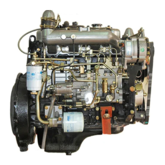
User Manuals: Isuzu 4BD1 Engine
Manuals and User Guides for Isuzu 4BD1 Engine. We have
2
Isuzu 4BD1 Engine manuals available for free PDF download: Workshop Manual
Isuzu 4BD1 Workshop Manual (217 pages)
4B-6B SERIES
Brand:
Isuzu
| Category:
Engine
| Size: 7.32 MB
Table of Contents
Table of Contents
2
General Information
3
General Repair Instructions
4
Symbols Used in the Manual
6
Main Data and Specifications
8
Design Features and General Outline
11
Main Engine Parts and Their Function
11
Cylinder Head
11
Cylinder Body
12
Crankshaft
12
Pistons
13
Valve Mechanism
13
Tightening Torque Specifications
14
Angular Nut and Bolt Tightening Method
15
Major Part Fixing Nuts and Bolts
17
Cylinder Head and Cover
17
Cylinder Body Diagram
18
Oil Pan and Dipstick Diagram
19
Camshaft and Rocker Arm Diagram
20
Crankshaft, Piston and Flywheel Diagram
21
Thermostat and Thermostat Housing Diagram
22
Intake and Exhaust Manifold Diagram
23
Timing Gear Case and Flywheel Housing Diagram
24
Oil Cooler, Oil Filter, and Oil Pump Diagram
25
Fuel System Diagram
26
Turbocharger Diagram
27
Identifications
28
Engine Serial Number
28
Injection Pump Number
28
Maintenance
29
Lubricating System Maintenance
30
Main Oil Filter Replacement
30
Center Bolt Type Removal/Installation
30
Cartridge (Spin-On) Type Removal/Installation
30
Fuel System Maintenance
31
Fuel Filter Replacement
31
Injection Nozzle Maintenance
32
Spray Condition Check (During Injection Nozzle Tester Operation)
33
Water Separator (Water Sedimentor) Check
34
Air Bleeding Check
34
Cooling System Maintenance
35
Valve Clearance and Adjustment
35
Cooling Fan Drive Belt Adjustment
35
Thermostat Inspection
35
Injection Timing
37
Flange Mounted Injection Pump Injection Timing Checking and Adjustment
37
Injection Timing Checking Procedure
38
Coupling Driven Injection Pump Timing Adjustment
41
Compression Pressure Measurement
43
Turbocharger Inspection
44
Engine Repair-Kit (for Non-Turbocharged Engines) Diagram
45
Engine Repair Kit (for Turbocharged Engines) Diagram
46
Recommended Lubricants
47
Engine Oil Viscosity Chart
47
Engine Assembly I (Disassembly)
49
External Parts Disassembly Steps
50
Model 6BD1T Right Side View/Disassembly Steps
50
Model 4BD1T View/Disassembly Steps
51
Injection Pump with Injection Pump Gear
52
Flange Mounted Injection Pump Removal
52
Coupling Mounted Injection Pump Removal
52
Remove of the Air Compressor (if Equipped)
52
Model 6BD1T Left Side View/Disassembly Steps
53
Model 4BD1T Left Side View/Disassembly Steps
54
Major Components/Disassembly Steps
55
Rocker Arm Shaft
56
Cylinder Head Bolts
56
Crankshaft Pulley Nut
56
Taper Bushing (6B Series Only)
57
Flywheel
57
Major Components II/Disassembly Steps
58
Idler Gear
59
Cam Shaft
59
Crankshaft Bearing Cap
59
Rocker Arm and Rocker Arm Shaft View/Disassembly Steps
60
Cylinder Head View/Disassembly Steps
61
Split Collar Removal
61
Piston and Connecting Rod View/Disassembly Steps
62
Piston Rings Removal
63
Snap Ring and Piston Pin Removal
63
Engine Assembly II (Inspection and Repair)
65
Cylinder Head Lower Face Warpage Check
66
Water Jacket Water Pressure Test
66
Valve Stem and Valve Guide Clearance
67
Valve Guide Replacement/Removal
67
Valve Depression
68
Valve Contact Width
68
Valve Seat Insert Replacement/Removal
68
Valve Seat Installation
69
Valve Seat Insert Correction
69
Valve Spring Free Length Measurement
70
Valve Spring Inclination
71
Valve Spring Tension
71
Tappet (Cam Follower or Valve Lifter) Inspection
71
Push Rod Inspection
72
Rocker Arm Correction
72
Rocker Arm Shaft and Rocker Arm Inspection
72
Rocker Arm Shaft Outside Diameter Measurement
72
Idler Gear and Idler Gear Shaft Inspection
73
Rocker Arm Shaft and Rocker Arm Clearance Check
73
Camshaft Inspection
74
Cylinder Liner Bore Measurement
75
Cylinder Liner Projection Inspection
76
Cylinder Liner Replacement
76
Cylinder Bore Measurement
77
Cylinder Liner Grade Selection
77
Cylinder Body Inside Diameter Measurement
77
Cylinder Liner Outside Diameter Measurement
78
Cylinder Bore and Cylinder Liner Outside Diameter Combinations
78
Cylinder Liner Installation
79
Piston Grade Selection
79
Cylinder Liner Bore Measurement/Piston Outside Diameter
80
Cylinder Liner Bore and Piston Clearance
81
Piston Ring and Piston Ring Groove Clearance
82
Piston Ring and Piston Groove Clearance
82
Piston Ring Gap
82
Piston Pin Outside Diameter
83
Piston Pin and Piston Clearance
83
Piston Pin and Piston Pin Hole Clearance
83
Connecting Rod Alignment
84
Piston Pin and Connecting Rod Small End Bushing Clearance
84
Connecting Rod Bushing Replacement
84
Connecting Rod Bearing Inspection
85
Crankshaft and Bearing Inspection
86
Crankshaft Journal and Crankpin Outside Diameter
86
Crankshaft Journal and Bearing Clearances
87
Crankshaft Journal Bearing Inside Diameter
88
Connecting Rod Bearing Inside Diameter
88
Crankshaft Run-Out
89
Main Bearing and Connecting Rod Bearing Tension
89
Crankshaft Regrinding
89
Crankshaft Regrinding Procedure
90
Crankshaft Grinding Limit
90
Plastigage Clearance Measurement
91
Crankshaft Journal Bearing Clearance
91
Crankshaft Pin Bearing Clearance
92
Crankshaft Tufftriding Inspection
92
Oil Seal Wear Ring Replacement (6BD1T, 6BG1, 6BG1T)
93
Crankshaft Gear Inspection
93
Crankshaft Gear Replacement
94
Flywheel and Flywheel Housing (Rear Oil Seal) Inspection
94
Rear Gear Inspection/Replacement/Installation
94
Flywheel Housing Oil Seal Replacement
94
Timing Gear Case Cover Inspection
95
Crankshaft Front Oil Seal Replacement
95
Engine Assembly III (Reassembly)
97
Piston and Connecting Rod Reassembly Steps - Minor Component
98
Pistons Heating/ Connecting Rod Installation
99
Piston Pin Snap Ring Installation
99
Piston Ring Installation
99
Connecting Rod Bearing Installation
99
Cylinder Head Reassembly Steps
100
Valve Stem Oil Seal Installation
101
Intake and Exhaust Valves Installation
101
Intake and Exhaust Valve Springs Installation
101
Spring Seat Split Collar Installation
101
Intake Manifold and Gasket Installation
102
Exhaust Manifold and Gasket Installation
102
Rocker Arm and Rocker Arm Shaft Reassembly Steps
104
Major Component Reassembly Steps I
105
Oil Jet Installation
106
Crankshaft Bearing Configuration
106
Crankshaft Installation
106
Thrust Bearing Installation
106
Crankshaft Bearing Cap Installation
107
Timing Gear Case Installation
107
Camshaft/Thrust Plate Bolts Tightening
107
Idler Gear Shaft Installation
107
Idler Gear Installation
108
Piston and Connecting Rod Installation
108
Oil Pump and Coupling Installation
109
Flywheel Housing Installation
109
Oil Pan Installation
110
Oil Cooler Installation
110
Major Component Reassembly Steps II
111
Flywheel Installation
112
Injection Pump and Injection Pump Gear Assembly
112
Air Compressor Installation
112
Tappet Chamber Cover Installation
113
Water Pump Installation
113
Cylinder Head Gasket/Bolt Installation
113
Rocker Arm and Rocker Arm Shaft Installation
115
External Parts Reassembly Steps (Left-Hand Side)
116
Cylinder Head Cover Installation
117
Fan Belt Adjustment
117
Starter Motor Installation
117
Turbocharger Mounting Flange Gasket Positioning
118
Turbocharger Nuts Tightening
118
Oil Drain Pipe Installation
118
Oil Feed Pipe Installation
119
Turbo Adaptor Tightening
119
External Parts Reassembly Steps (Right-Hand Side) - Model 6BD1T
120
Injection Nozzle Installation
121
Fuel Injection Pipe and Fuel Leak off Pipe Installation
121
Oil Filter Installation
121
Fuel Pipe, Fuel Return Pipe, Intake Pipe Installation
122
Injection Timing Adjustment
122
Engine Tuning Operation
123
Engine Sectional View
125
Lubricating System
127
Lubricating System - General Description
128
Oil Pump Disassembly
129
Oil Pump Drive Gear Inspection
130
Oil Pump Driven Gear Inspection
130
Main Oil Filter Disassembly/Inspection and Repair
131
Lubricating System Reassembly
132
Center Bolt and Drain Plug Installation
132
Oil Cooler Disassembly, Inspection and Repair
133
Lubricating System Reassembly Steps
134
Oil Cooler Element Installation
134
Cooling System
135
Cooling System - General Description
136
Water Pump Disassembly Steps
137
Impeller/Pulley Center/Snap Ring Removal
138
Spindle, Bearing, Spacer/Seal Unit, Washer and Seal Removal
138
Bearing Replacement
139
Cooling System Reassembly Steps
140
Spindle, Bearing, and Spacer Installation
141
Snap Ring/Pulley Center Installation
141
Seal Unit, Washer and Seal Installation
141
Impeller/Pulley Installaton
142
Thermostat Inspection and Repair
142
Fuel System
143
Fuel System - General Description
144
Fuel Filter Disassembly/Inspection and Repair
145
Injection Nozzle Disassembly
147
Push Rod Spring Check
148
Nozzle Holder Push Rod Check
148
Injection Nozzle Check
148
Fuel Filter Reassembly Steps
149
Injection Pipe Connector/Injection Nozzle/Retaining Nut Check
150
Injection Starting Pressure Adjustment
150
Nozzle Holder Cap Nut Check
151
Injection Pump Calibration Data
152
Identification Plate and Product Serial Number
152
Test Conditions Required for the Fuel Injection Amount Adjustment
152
Inj. Pump Calibration Data
153
Governor Adjustment
154
Turbocharger
155
Turbocharger - General Description
156
Turbocharger Identification
157
Rotor Shaft Play Inspection
158
Rotor Shaft Axial Play Measurement
158
Air Compressor
159
Air Compressor Sectional View/Main Data
160
Air Compressor Disassembly Steps
161
Air Compressor Inspection and Repair
162
Air Compressor Reassembly Steps
164
Connecting Rod/Bearing Cover Installation
165
Cylinder Body/Cylinder Head Installation
165
Engine Electricals
167
Starter Motor Identification
168
Nikko Identification Plate
168
Hitachi Identification Plate
168
Starter Motor Main Data and Specifications
169
Starter Motor Sectional View
171
Starter Motor Exploded View
172
Alternator Identification
173
Alternator Main Data and Specifications
174
Regulator Main Data and Specifications
176
Alternator Sectional View
177
Alternator Exploded View
178
Troubleshooting
179
Hard Starting
180
Starter Inoperative
180
Starter Motor Operates but Engine Does Not Turn over
181
Engine Turns over but Does Not Start, Fuel Is Being Delivered to the Injection Pump
182
Engine Turns over but Does Not Start
183
Unstable Low Idling
184
Unsufficient Power
187
Excessive Fuel Consumption
190
Overheating
193
White Exhaust Smoke
195
Dark Exhaust Smoke
196
Oil Pressure Does Not Rise
197
Abnormal Engine Noise
199
Engine Knocking
199
Gas Leakage Noise
199
Continuous Noise
200
Slapping Noise
201
Special Tool List
203
Conversion Table
207
Length Conversion Table
207
Area Conversion Table
209
Volume Conversion Table
209
Mass Conversion Table
211
Pressure Conversion Table
212
Torque Conversion Table
213
Temperature Conversion Table
214
Advertisement
Isuzu 4BD1 Workshop Manual (174 pages)
For automotive use 1986-
Brand:
Isuzu
| Category:
Engine
| Size: 22.26 MB
Table of Contents
Section 1
3
Table of Contents
3
General Repair Instructions
4
How to Use this Manual
4
Main Data and Specifications
7
Torque Sp· E Cifications
9
How to Tighten by Angular Tightening Method
10
Engine Repair Kit
19
Servicing
20
Recommended Lubricants
28
Engine Oil Viscosity Chart
28
Adhesive for Repairs
28
Section 2
29
General Description
30
Disassembly
31
Inspection and Repair
42
Reassembly
60
Section 3
112
Starter Motor
117
Alternator and Regulator
120
Vacuum Pump
143
Control Resistor
144
Glow Plugs
144
Section 4
145
General Description
146
Main Data and Specification
146
Disassembly
147
Inspection and Repair
148
Reassembly
149
Advertisement
Related Products
Isuzu 4BB1
Isuzu 4BD1T
Isuzu 4BG1
Isuzu 4ja1
Isuzu 4JB1T
Isuzu 42
Isuzu 4LE2-PW10
Isuzu 4LB1
Isuzu 4HK1-TC
Isuzu 4HK1-TCS
Isuzu Categories
Engine
Automobile
Utility Vehicle
Trucks
Control Systems
More Isuzu Manuals
Login
Sign In
OR
Sign in with Facebook
Sign in with Google
Upload manual
Upload from disk
Upload from URL