Sign In
Upload
Manuals
Brands
IRIS Manuals
Measuring Instruments
700DC
IRIS 700DC Flame Monitoring System Manuals
Manuals and User Guides for IRIS 700DC Flame Monitoring System. We have
1
IRIS 700DC Flame Monitoring System manual available for free PDF download: Applications Manual
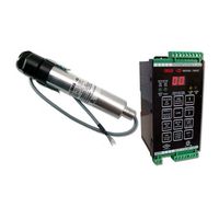
IRIS 700DC Applications Manual (35 pages)
FLAME MONITORING SYSTEM, SIGNAL PROCESSOR AND VIEWING HEAD
Brand:
IRIS
| Category:
Measuring Instruments
| Size: 0.9 MB
Table of Contents
Table of Contents
2
General Description
4
Ir Detector
5
Uv Detector
5
Self-Checking
5
Internal Parameter Storage
5
Model 700 Power Connections
6
Viewing Head Connector and Wiring
6
Protecting the Viewing Head Cable
7
Green and Red Led Indicators
7
Viewing Head Mounting Block
7
Setting the Viewing Head Gain
7
Adjustment of Vh Sighting and Gain
8
Orificing
8
Manual Setup of Set Points - Models 700 & 800
8
Automatic Setup - Model 700 Only
9
Filter Selection for Ir Viewing Head
10
Loading Factory Defaults
10
Setting Ffrt - Models 700 and 800
11
Ma/4-20 Ma Option - Models 700 & 800
11
Lockout or Faulty Vh Indication
11
Panel Lock
11
Panel Lock with no Vh Connected
11
Working with Older Uv Viewing Heads
11
Model 700 Communications
12
Model 800 Communications
12
Approvals
12
Contact Information
12
Figure 1 - Model 700Ac Signal Processor
13
Figures 1-16 and Flow Charts 1-9
13
Figure 2 - Model 700Ac Signal Processor Wiring
14
Figure 3 - Model 700Dc Signal Processor
15
Figure 4 - Model 700Dc Signal Processor Wiring
16
Figure 5 - Model 800 Signal Processor on Din Rail
17
Figure 7 - Model S702 and S706 Viewing Heads
18
Figure 8 - Model S802 and S806 Viewing Heads
19
Figure 11 - Model 700 Viewing Head Cable with 1/2" Npt Fitting
21
Processor
22
Figure 14 - Communications Cable for Model 800 Sp
23
Flow Chart 1 - Setting Factory Defaults
25
Flow Chart 2 - Auto Setup
26
Flow Chart 3 - Auto Setup
27
Flow Chart 4 - Auto Setup
28
Flow Chart 5 - Manual Flame on Setup
29
Flow Chart 6 - Manual Flame off Setup
30
Flow Chart 7 - Flame Failure Response Time (Ffrt) Setup
31
Flow Chart 8 - 0-20/4-20Ma Analog Output Setup
32
Flow Chart 9 - Viewing Head Gain Setting
33
Specifications for Series 700 and 800 Viewing Heads
34
Specifications for Model 700Ac & Model 700Dc Signal Processors
35
Specifications for Model 800 Signal Processor
35
Advertisement
Advertisement
Related Products
IRIS 700 Series
IRIS 700AC
IRIS 75
IRIS 800
IRIS iChem 100
IRIS IRIS804
IRIS IRIS808
IRIS IRIS816
IRIS IRMA MATRIX 2
IRIS IRMA MATRIX Door Clear
IRIS Categories
Scanner
Measuring Instruments
Fan
Security Camera
Security System
More IRIS Manuals
Login
Sign In
OR
Sign in with Facebook
Sign in with Google
Upload manual
Upload from disk
Upload from URL