Sign In
Upload
Manuals
Brands
Intel Manuals
Computer Hardware
Core i7-3820
Intel Core i7-3820 Quad-Core Processor Manuals
Manuals and User Guides for Intel Core i7-3820 Quad-Core Processor. We have
3
Intel Core i7-3820 Quad-Core Processor manuals available for free PDF download: Design Manual, Datasheet, Product Overview
Intel Core i7-3820 Design Manual (124 pages)
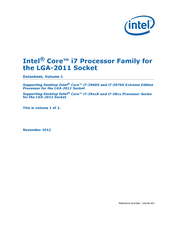
Core i7 Extreme Edition Processor Family for the LGA2011-0 Socket
Brand:
Intel
| Category:
Computer Hardware
| Size: 5.23 MB
Table of Contents
Table of Contents
3
Revision History
9
1 Introduction
11
Platform LGA2011-0 Socket Stack with Tall-Heat Pipe Heatsink
11
References
12
Definition of Terms
12
Reference Documents
12
Terms and Descriptions
12
2 Package Mechanical Specifications
15
Processor Package Assembly Sketch
15
Core™ I7-3960X, I7-3970X Processor Extreme Edition, Intel
15
Package Mechanical Drawing
16
Processor Component Keep-Out Zones
16
Package View
16
Package Loading Specifications
17
Package Handling Guidelines
17
Package Insertion Specifications
17
Processor Mass Specification
17
Processor Loading Specifications
17
Processor Materials
18
Processor Markings
18
Processor Top-Side Markings
18
3 LGA2011-0 Socket
19
Hexagonal Array in LGA2011-0
19
LGA2011-0 Socket Attributes
19
Contact Wiping Direction
20
Schematic of LGA2011-0 Socket with Pick and Place Cover Removed
20
LGA2011-0 Socket Contact Numbering (Top View of Socket)
21
Contact/Land Mating Location
22
Board Layout
22
Offset between LGA Land Center and Solder Ball Center
22
Attachment to Motherboard
23
LGA2011-0 Socket Land Pattern (Top View of Board)
23
Socket Components
24
Contacts
24
Pick and Place Cover
24
Socket Body Housing
24
Solder Balls
24
LGA2011-0 Pick and Place Cover
25
Pick and Place Cover
25
Socket Standoffs and Package Seating Plane
26
Durability
26
Markings
26
Component Insertion Forces
26
Socket Size
26
4 Independent Loading Mechanism (ILM)
27
Square ILM Design Concept
28
Square ILM Assembly Design Overview
28
Square ILM Part Terminology
28
Square ILM Assembly
28
ILM as Universal Retention Mechanism
29
Square ILM Assembly Component Thickness and Material
29
ILM Features
30
ILM Closing Sequence
30
ILM Interlocking Feature
30
ILM Opening Sequence
31
ILM Lever Closing Sequence
31
Opening ILM
32
Opening Sequence for ILM and Loadplate (Cont.)
32
ILM Keying
33
ILM Back Plate Design Overview
33
ILM Back Plate
33
ILM Assembly
34
Manufacturing Assembly Flow
34
Assembling Socket, Back Plate and ILM Onto the Motherboard
34
Processor Installation
35
Optional Step: Lock down the Hinge Lever
35
ILM Cover
36
Pin 1 Markings on the ILM Frame
36
Closing ILM and Loadplate
36
Heatsink to ILM Interface
37
ILM with Cover
37
Heatsink to ILM Interface
38
5 LGA2011-0 Socket and ILM Electrical, Mechanical, and Environmental Specifications
39
Component Mass
39
Package/Socket Stackup Height
39
Socket and Retention Component Mass
39
2011-Land Package and LGA2011-0 Socket Stackup Height
39
Loading Specifications
40
Electrical Requirements
40
Socket and ILM Mechanical Specifications
40
Environmental Requirements
41
Flow Chart of Knowledge-Based Reliability Evaluation Methodology
41
Electrical Requirements for LGA2011-0 Socket
41
6 Thermal Management Specifications
43
Package Thermal Specifications
43
Thermal Specifications
43
And DTS Based Thermal Specifications
44
Ttv Tcase
44
Thermal Specification
44
Processor Thermal Specifications
44
TTV Thermal Profile
45
Processor Specification for Operation Where Digital Thermal Sensor Exceeds TCONTROL
46
Core™ I7-3930K
46
Thermal Metrology
47
Processor Core Thermal Features
48
Processor Temperature
48
Adaptive Thermal Monitor
48
Frequency/Svid Control
49
Frequency and Voltage Ordering
49
Clock Modulation
50
On-Demand Mode
50
PROCHOT_N Signal
50
THERMTRIP_N Signal
51
Platform Environment Control Interface (PECI)
51
Introduction
51
PECI Client Capabilities
52
Fan Speed Control with Digital Thermal Sensor
52
7 PECI Interface
53
Platform Environment Control Interface (PECI)
53
Wrpkgconfig()
53
Rdiamsr()
53
Summary of Processor-Specific PECI Commands
53
PECI Client Capabilities
54
Platform Manageability
54
Processor Interface Tuning and Diagnostics
54
Thermal Management
54
Processor, and Intel
54
Client Command Suite
55
Ping()
55
Ping() Example
55
Getdib()
56
Device Info Field Definition
56
Revision Number Definition
57
Minor Revision Number Meaning
57
Gettemp()
58
Gettemp() Example
58
Rdpkgconfig()
59
Gettemp() Response Definition
59
Rdpkgconfig() Response Definition
60
Wrpkgconfig()
61
Package Configuration Capabilities
62
Wrpkgconfig() Response Definition
62
Rdpkgconfig() & Wrpkgconfig() DRAM Thermal Services Summary
63
DRAM Thermal Estimation Configuration Data
64
Channel & DIMM Index Decoding
64
DRAM Rank Temperature Write Data
65
DIMM Temperature Read / Write
65
Ambient Temperature Reference Data
66
DRAM Channel Temperature
66
Accumulated DRAM Energy Data
66
DRAM Power Info Read Data
67
DRAM Power Limit Data
67
Processor Thermal and Power Optimization Capabilities
68
DRAM Power Limit Performance Data
68
Processor
68
Rdpkgconfig() & Wrpkgconfig() Processor Thermal and Power Optimization Services Summary
68
CPUID Data
71
Platform ID Data
71
Platform ID Encoding
71
Uncore Device ID
72
Maximum Thread ID
72
Processor Microcode Revision
72
Package Power SKU Unit Data
72
Package Power SKU Data
73
Power Control Register Unit Calculations
73
Package Temperature Read Data
74
Temperature Target Read
74
Per Core Temperature Read
75
Thermal Status Word
75
Thermal Averaging Constant Write / Read
75
ACPI P-T Notify Read/Write
76
Accumulated Energy Status Read
76
Current Limit Read
76
Thermally Constrained Time Read
76
Current Config Limit Read Data
76
Accumulated Energy Read Data
76
Power Limit for the V
77
Package Power Limits for Multiple Turbo Modes
77
CC Power Plane Write / Read
77
Power Limit Data for
77
CC Power Plane
77
Socket Performance Indication Read
78
Socket Power Limit Performance Status Read
78
Socket Power-Performance Scalability Read
78
Socket Power Limit Performance Data
78
Socket Power-Performance Scalability Data
78
Socket Performance Indication Data
78
Rdiamsr()
79
Processor ID Construction Example
80
Rdiamsr() Response Definition
81
Rdiamsr() Services Summary
81
Rdpciconfig()
82
PCI Configuration Address
82
Rdpciconfig() Response Definition
83
Rdpciconfiglocal()
84
PCI Configuration Address for Local Accesses
84
Rdpciconfiglocal() Response Definition
85
Wrpciconfiglocal()
86
Wrpciconfiglocal() Response Definition
87
Client Management
88
Power-Up Sequencing
88
Wrpciconfiglocal() Memory Controller Device/Function Support
88
PECI Client Response During Power-Up
88
Device Discovery
89
Client Addressing
89
SOCKET ID Strapping
89
C-States
90
S-States
90
Power Impact of PECI Commands Versus C-States
90
Processor Reset
91
Processor Error Handling
91
Originator Retry and Timeout Policy
92
Enumerating PECI Client Capabilities
92
Multi-Domain Commands
92
Domain ID Definition
92
Client Responses
93
Abort FCS
93
Completion Codes
93
Multi-Domain Command Code Reference
93
Completion Code Pass/Fail Mask
93
Originator Responses
94
Device Specific Completion Code (CC) Definition
94
Originator Response Guidelines
94
DTS Temperature Data
95
Format
95
Interpretation
95
Temperature Sensor Data Format
95
Temperature Filtering
95
Reserved Values
96
Error Codes and Descriptions
96
8 Thermal Solutions
97
Performance Targets
97
Reference Heatsink Assembly
97
Radial Fin Heatsink Assembly
97
Processor Reference Thermal Boundary Conditions
97
Assembly Process for Reference Heatsinks
98
Tall Heat Pipe Heatsink Assembly
98
Geometric Envelope for the Intel® Reference ATX Thermal Mechanical Design
99
ATX KOZ 3-D Model Primary (Top) Side
99
Reference Heat Sink Clearance above the Motherboard
99
Structural Considerations
100
Attachment to the ILM
100
Thermal Interface Material
100
Intel® Reference Thermal Solution TIM
100
Tall Heat Pipe Heat Sink Performance
101
T-HPHS Psi-Ca Versus RPM
101
T-HPHS Sound Power (BA) Versus RPM
101
Thermal Design Guidelines
102
Intel® Turbo Boost 2 Technology
102
Thermal Characterization Parameter
102
Fan Speed Control
103
Processor Thermal Characterization Parameter Relationships
103
9 Quality and Reliability Requirements
105
Use Conditions
105
Use Conditions Environment (System Level)
105
Intel ® Reference Component Validation
106
Board Functional Test Sequence
106
Use Conditions Environment (System Level)
106
Post-Test Pass Criteria Examples
107
Recommended Bios/Processor/Memory Test Procedures
107
Material and Recycling Requirements
107
A Mechanical Drawings
109
Mechanical Drawing List
109
Board Keepin / Keepout Zones (Sheet 1 of 2)
110
Board Keepin / Keepout Zones (Sheet 2 of 2)
111
B Socket Mechanical Drawings
113
Socket Drawing List
113
Socket Mechanical Drawing (Sheet 1 of 4)
114
Socket Mechanical Drawing (Sheet 2 of 4)
115
Socket Mechanical Drawing (Sheet 3 of 4)
116
Socket Mechanical Drawing (Sheet 4 of 4)
117
C Component Suppliers
119
Suppliers for the LGA2011-0 Socket and ILM
120
Suppliers for the LGA-2011-0 Socket and ILM (Continued)
120
D Package Mechanical Drawings
121
Mechanical Drawing List
121
Processor Package Drawing (Sheet 1 of 2)
122
Processor Package Drawing (Sheet 2Of 2)
123
Advertisement
Intel Core i7-3820 Datasheet (120 pages)
Core i7 Extreme Edition Processor Family for the LGA-2011 Socket
Brand:
Intel
| Category:
Computer Hardware
| Size: 0.91 MB
Table of Contents
Table of Contents
3
Revision History
7
1 Introduction
9
Processor Feature Details
10
Supported Technologies
10
Processor Platform Block Diagram Example
10
Interfaces
11
System Memory Support
11
PCI Express
11
PCI Express* Lane Partitioning and Direct Media Interface Gen 2 (DMI2)
12
Direct Media Interface Gen 2 (DMI2)
13
Platform Environment Control Interface (PECI)
13
Power Management Support
13
Processor Package and Core States
13
System States Support
13
Memory Controller
13
PCI Express
13
Thermal Management Support
14
Package Summary
14
Terminology
14
Related Documents
16
Reference Documents
16
2 Interfaces
17
System Memory Interface
17
System Memory Technology Support
17
System Memory Timing Support
17
PCI Express* Interface
17
PCI Express* Architecture
17
Data Link Layer
18
Transaction Layer
18
PCI Express* Layering Diagram
18
Packet Flow through the Layers
18
Physical Layer
19
PCI Express* Configuration Mechanism
19
DMI2/PCI Express* Interface
19
DMI2 Error Flow
19
DMI2 Link down
20
Platform Environment Control Interface (PECI)
20
3 Technologies
21
Intel Virtualization Technology (Intel VT)
21
And IA-32 Intel
21
Virtualization Technology
21
Architecture
21
VT) for Intel
21
VT-X) Objectives
21
And IA-32 Intel
22
Intel Directed I/O
22
Virtualization Technology
22
VT) for
22
VT-D) Objectives
22
VT-X) Features
22
Virtualization Technology
23
VT) for Directed I/O
23
VT-D) Features Supported
23
Intel Virtualization Technology Processor Extensions
23
Intel
23
VT-D) Processor Feature Additions
23
Security Technologies
24
Intel ® AES New Instructions (Intel ® AES-NI)
24
Intel
24
Execute Disable Bit
24
HT Technology)
24
Hyper-Threading Technology
25
Intel Turbo Boost Technology
25
Enhanced Intel Speedstep Technology
25
Intel ® Turbo Boost Operating Frequency
25
Intel Advanced Vector Extensions (Intel AVX)
26
4 Power Management
27
Advanced Configuration and Power Interface (ACPI) States Supported
27
System States
27
Processor Package and Core States
27
Package C-State Support
28
Core C-State Support
28
Integrated Memory Controller States
29
DMI2 / PCI Express* Link States
29
DMI2/PCI Express* Link States
29
System Memory Power States
29
G, S, and C State Combinations
30
Processor Core / Package Power Management
30
Enhanced Intel ® Speedstep ® Technology
30
Low-Power Idle States
31
Idle Power Management Breakdown of the Processor Cores
31
Thread and Core C-State Entry and Exit
31
Requesting Low-Power Idle States
32
Core C-States
32
P_Lvlx to MWAIT Conversion
32
Core C0 State
33
Core C1/C1E State
33
Core C3 State
33
Core C6 State
33
Core C7 State
33
C-State Auto-Demotion
33
Package C-States
34
Package C0
35
Package C1/C1E
35
Package C-State Entry and Exit
35
Coordination of Core Power States at the Package Level
35
Package C2 State
36
Package C3 State
36
Package C6 State
36
Package C-State Power Specifications
37
System Memory Power Management
37
CKE Power-Down
37
Self Refresh
38
DLL and PLL Shutdown
38
Self Refresh Entry
38
Self Refresh Exit
38
DRAM I/O Power Management
38
DMI2 / PCI Express* Power Management
38
5 Thermal Management Specifications
39
6 Signal Descriptions
41
System Memory Interface
41
Memory Channel DDR0, DDR1, DDR2, DDR3
41
PCI Express* Based Interface Signals
42
Memory Channel Miscellaneous
42
PCI Express* Port 1 Signals
42
PCI Express* Port 2 Signals
43
PCI Express* Port 3 Signals
43
DMI2 / PCI Express* Port 0 Signals
44
Platform Environment Control Interface (PECI) Signal
44
System Reference Clock Signals
44
PCI Express* Miscellaneous Signals
44
DMI2 to Port 0 Signals
44
PECI Signals
44
System Reference Clock (BCLK{0/1}) Signals
44
JTAG and TAP Signals
45
Serial VID Interface (SVID) Signals
45
SVID Signals
45
Processor Asynchronous Sideband and Miscellaneous Signals
46
Processor Asynchronous Sideband Signals
46
Miscellaneous Signals
46
Processor Power and Ground Supplies
48
Power and Ground Signals
48
7 Electrical Specifications
49
Processor Signaling
49
System Memory Interface Signal Groups
49
PCI Express* Signals
49
DMI2/PCI Express* Signals
49
Platform Environmental Control Interface (PECI)
49
Input Device Hysteresis
50
System Reference Clocks (BCLK{0/1}_DP, BCLK{0/1}_DN)
50
PLL Power Supply
50
JTAG and Test Access Port (TAP) Signals
51
Processor Sideband Signals
51
Power, Ground and Sense Signals
51
Power and Ground Lands
51
Decoupling Guidelines
52
Voltage Identification (VID)
52
VR Power-State Transitions
54
SVID Address Usage
54
Voltage Identification Definition
55
Reserved or Unused Signals
56
Signal Group Summary
56
Signal Description Buffer Types
56
Signal Groups
57
Power-On Configuration (POC) Options
59
Signals with On-Die Termination
59
Power-On Configuration Option Lands
59
Absolute Maximum and Minimum Ratings
60
Storage Conditions Specifications
60
Processor Absolute Minimum and Maximum Ratings
60
DC Specifications
61
Voltage and Current Specifications
61
Voltage Specification
61
Current (Icc_Max and Icc_Tdc) Specification
62
Die Voltage Validation
63
VCC Overshoot Specifications
63
VCC Overshoot Example Waveform
63
Overshoot Specifications
63
Signal DC Specifications
64
DDR3 Signal DC Specifications
64
PECI DC Specifications
65
System Reference Clock (BCLK{0/1}) DC Specifications
66
Smbus DC Specifications
66
JTAG and TAP Signals DC Specifications
67
Serial VID Interface (SVID) DC Specifications
67
Processor Asynchronous Sideband DC Specifications
68
PCI Express* DC Specifications
69
DMI2 / PCI Express* DC Specifications
69
Reset and Miscellaneous Signal DC Specifications
69
Miscellaneous Signals DC Specifications
69
8 Processor Land Listing
71
Land Name
72
Land Number
95
9 Package Mechanical Specifications
119
Intel Core i7-3820 Product Overview (2 pages)
2nd Generation Intel Core i7 Processor Extreme Edition
Brand:
Intel
| Category:
Computer Hardware
| Size: 0.43 MB
Advertisement
Advertisement
Related Products
Intel i7-3770T
Intel i7-3770S
Intel i7-3770K
Intel i7-3770
Intel Core i7-3960X
Intel Core i7-3930K
Intel Core i7-3970X
INTEL CORE I7-610E - DATASHEET ADDENDUM
Intel Core i7-2600 Gain
Intel Core i7-980X
Intel Categories
Motherboard
Computer Hardware
Server
Server Board
Desktop
More Intel Manuals
Login
Sign In
OR
Sign in with Facebook
Sign in with Google
Upload manual
Upload from disk
Upload from URL