Sign In
Upload
Manuals
Brands
Instrumentarium Manuals
Medical Equipment
Orthopantomograph OP200 D
Instrumentarium Orthopantomograph OP200 D Manuals
Manuals and User Guides for Instrumentarium Orthopantomograph OP200 D. We have
3
Instrumentarium Orthopantomograph OP200 D manuals available for free PDF download: User Manual, Installation Manual, Service Program Manual
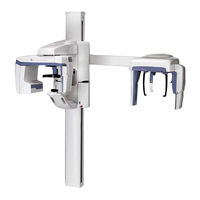
Instrumentarium Orthopantomograph OP200 D User Manual (154 pages)
Brand:
Instrumentarium
| Category:
Dental equipment
| Size: 15.75 MB
Table of Contents
Table of Contents
5
Introduction
9
General
9
Markings and Graphics Symbols
10
Type and Version
11
Options, Accessories and Manuals
13
Radiation Protection Guidelines
14
Protection by Distance
14
Laser Lights
15
Control from a Protected Environment
15
Emergency Stop Switch
16
Manufacturer's Liability
16
Disposal
17
OP200 D Controls and Accessories
19
OP200 D Main Parts
19
OC200 D Main Parts
23
Control Panel
24
Positioning Panels
27
Patient Positioning Accessories
28
Disposables & Service Accessories
30
Changing the Fuses
32
Equipment Care and Preparations
33
Care Instructions
33
Cleaning Recommendations
33
Cleaning
33
Disinfection and Sterilization
34
Autoclave
34
Steam Sterilization
34
Ethylene Oxide Sterilization
35
Other Sterilization Processes
35
Dry Heat Sterilization
35
Liquid Chemical Sterilant Gases
35
Chemical Sterilant Gases
35
Connecting and Disconnecting the CCD Sensor
36
Preparation for Panoramic Image Acquisition
38
Selecting Collimator Height with Automatic Collimator
40
Panoramic Procedures
41
P1: Standard Panoramic Exposure
41
P2: Pediatric Panoramic Exposure
49
P3: Ortho Zone Enhanced Panoramic Exposure
52
P4: Orthogonal Exposure
54
P5: Wide Arch Panoramic Exposure
56
Special Imaging Procedures
59
BW: Bitewing Exposure
59
P6: TMJ, Lateral Projection
60
P6: Ortho TMJ, Axial Corrected Lateral Projection (Optional)
64
P7: TMJ, Posterioranterior Projection
68
P8: Maxillary Sinus View
69
Cephalometric Procedures (Optional)
73
Preparing the Operation
73
P9A: Cephalo Core Lateral Projection P9B: Lateral Projection
73
P10: Cephalo Postero-Anterior (PA) Projection
76
P10: Reverse Towne Projection Exposure
78
P10: Waters View Exposure
79
P10: Carpus View Exposure (Holder Optional)
80
Imaging Technique
83
Automatic Exposure Control (AEC)
83
AEC Test
84
Exposure Technique Factors
84
Manual Mode
86
Free Selection of Kv and Ma
87
Test Mode
88
Measurements from the Image
89
Special Features
91
Basic Quality Assurance
91
Advanced QA (Optional)
92
Exposure Counter
93
Preventive Maintenance Reminder
93
Understanding the OP200 D Image
95
Failure Diagnostics
97
Failure Messages
97
Kv Display
97
Ma Display
98
Time Display
98
Resetting a Failure
98
Failure Codes
100
Diagnosing Image Quality Problems
101
Patient Positioning Problems
101
Image Appearance Problems
104
Artefacts
105
Unit Operation
106
How to Use the User Programming Mode
109
General
109
Installation and Unit Configuration Programs
109
Programs Affecting Image Quality
110
Other Pr Programs
111
How to Use the User Programming Mode
111
User Program Features
113
Pr 50 S3D: Volumetric Tomography Settings
113
Pr 51 PUS: Power up Settings
114
Pr 52 Pco and Pr 52 Gco: Constant Contrast & Density Settings
114
Pr 53 Nor: Resume Normal Settings
117
Pr 54 Arn: Rotating Unit Autoreturn
118
Pr 57 Hon: Patient Positioning Side
118
Pr 58 CON: Vertebrae Shadow Compensation
119
Pr 59 PSE: Preventative Maintenance Reminder
121
Pr 60 Bep: Panel Beep
122
Pr 61 CLC: Clear Exposure Counter
123
Pr 62 ERR: Last Failure Code
123
Pr 63 CEL: Cephalostat Exposure Limit
124
Pr 64 Fst: Fast Scanning Selection
124
Pr 65 Dos: Dose / Time Display Selection
125
Pr 66 COU: Exposure Counters
127
Pr 67 Qua: Quality Assurance
128
User Statement
129
Dose Area Product (DAP)
134
Technical Specifications
137
Electromagnetic Compatibility (EMC) Tables
146
Maintenance
153
Maintenance Schedule
153
Monthly Inspection by User
153
Preventive Maintenance Reminder
154
Advertisement
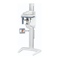
Instrumentarium Orthopantomograph OP200 D Installation Manual (141 pages)
Brand:
Instrumentarium
| Category:
Dental equipment
| Size: 43.83 MB
Table of Contents
Table of Contents
5
Introduction
9
General
9
Graphics Symbols
11
Type and Version
13
Radiation Protection Guidelines
15
Protection by Distance
15
Control from a Protected Environment
16
Laser Lights
16
Emergency Stop Switch
17
Unit Identification Labels
18
Manufacturer's Liability
20
Disposal
21
Installation Requirements and Dimensions
23
Column Options
23
Column Mounting Options
24
OP/OC200 D Recommended Minimum Installation Dimensions
25
Unit Orientation Options
26
Site Requirements and Dimensions
27
Radiation Shielding
27
Radiation Safety
27
Package Dimensions
27
Door Width
27
Patient Access Area
27
Location
28
Unit Mounting
28
Floor
28
Remote Exposure Button (Optional)
28
Mains Connection
28
Protective Ground
29
Tools and Hardware
29
Preparing for the Installation
31
Checking the Shipment
31
Checking the Boxes
31
Opening the Boxes
31
Unpacking the Column
31
Unpacking the Carriage
33
Hardware Installation
35
Column Installation
35
Wall Mount Bracket
35
Optional Fork Stand Installation
38
Erecting the Column
40
Vertical Carriage Installation
42
Lifting and Fastening the Carriage
42
Adjusting and Fastening the Unit
46
Electrical Connections
47
Rotation Lock Removal
49
Carriage Locking Plate Removal
50
Digital Cephalostat Installation (Optional)
52
Preparing the Unit for Cephalostat Installation
52
Unpacking the Cephalostat
52
Cephalostat Arm Mounting
54
Cephalostat Electrical Connections
58
Cephalostat Head Mechanical Adjustments
59
Finalizing the Hardware Installation
62
Mains Voltage Connection
62
Changing the Mains Voltage from 230 V to 110 V
64
Removing Counterweight Transport Security Bolts
66
Control Panel
67
Remote Exposure Button (Optional)
67
Installing the Unit Covers
68
PCI-Board and Fiber-Optic Cable Installation
68
Connecting the CCD Sensor
69
Application Software Installation
70
Powering up the Unit for the First Time
70
Digital Unit Adjustments and Calibration
75
General Instructions
75
STEP 1: Panoramic Adjustments and Calibrations
76
Panoramic Beam Alignment Check
76
Panoramic Beam Adjustment with Autocollimator
78
Image Layer Check and Alignment
81
Patient Positioning Laser Lights Check and Alignment
83
AEC Calibration Check and Adjustment
89
STEP 2: Optional Cephalostat Adjustment and Calibration
91
Cephalostat Beam Passing the Panoramic CCD Sensor
91
Cephalostat Beam Check and Alignment
92
Secondary Collimator Check and Adjustment
95
Beam Alignment Board Sensors Sensitivity Check and Adjustment
98
Ear Holder Check and Alignment
100
Patient Positioning Laser Lights Alignment
103
Calibrating the Nasion Frequency
103
Installing Cephalostat Covers
104
Handing over the Unit
107
Panel Functions
107
Dose Settings
108
Quality Checks
108
Activating Panoramic QA-Mode
108
Activating Cephalostat QA-Mode
108
QA Test Mode Selection
109
QA-Image
109
IEC Quality Assurance
111
Accessories and Disposables
114
Application Training
114
Verifying Real Image Quality
115
Software Settings for Image Viewing
115
Appendix A, OP200 D Installation Check List
117
Appendix B, Unit Orientation Change
119
Panoramic Patient Positioning Orientation Change
119
Cephalostat Orientation Change
123
Appendix C, Cephalostat Upgrade
127
Cephalostat Upgrade Kit Content
127
Unpacking Instructions
129
Counter Weight
129
Adding Trim Weights
129
Collimator and Tubehead Cover
132
Installation of the Cephalostat
133
Alignments
133
Appendix D, Re-Packing Instructions
135
Preparing the Unit for Re-Packing
135
Cephalostat Head
135
Carriage
136
Cephalostat Package
138
Carriage Package
139
Column Package
141
Instrumentarium Orthopantomograph OP200 D Service Program Manual (42 pages)
Brand:
Instrumentarium
| Category:
Medical Equipment
| Size: 0.55 MB
Table of Contents
Table of Contents
5
1 Introduction
7
General
7
Exhibition Mode
7
Service Program Quick Reference
8
How to Use the Service Programs
10
2 Service Program Features
11
Sr 70 Log: Display Error Log
11
Approved: Äärynen Teemu 2008-05-19
12
Sr 71 Pay: Set Lease Period
13
Sr 72 LCA: Adjust Lateral TMJ Image Area (Film Units Only)
14
Sr 74 IOC: Display CPU Input/Output Signal Check
16
Reviewed: Rintamäki Markus 2008-05-16
21
Sr 76 PUP: X-Ray Tube Warm-Up
22
Sr 77 Prh: Adjust the Preheat Setting
24
Sr 78 Tha: Set Dose Calibration Constant (DCC)
25
Sr 79 SUP: Display Line Voltage
26
Sr 80 Crl: Test Motor Movement
26
Reviewed: Rintamäki Markus 2008-05-16
26
Sr 81 Bpl: Display Biteplate Properties (Volumetric Tomography Option Only)
28
Sr 82 COL: Set/Display Collimator Information
29
Sr 86 Sto: Store Settings
31
Sr 87 LAL: Set Linear Adjustment Value for VT
31
Sr 88 CAL: Disable Automatic Cephalostat Alignment Correction (Digital Units Only)
32
Sr 88 CAL: Set Cephalostat Alignment Value (Film Units Only)
33
Sr 89 COP: Set Country Options
33
Sr 90 PIN: Panorama Installation Program
36
Sr 91 CIN: Cephalostat Installation Program (Digital Units Only)
37
Sr 92 CHE: Set Level of Self-Checks
38
Sr 93 BAL: Adjust Beam Alignment Board Sensitivity
39
Advertisement
Advertisement
Related Products
Instrumentarium Orthopantomograph OP200
Instrumentarium Orthoceph OC200
Instrumentarium Orthoceph OC200 D
Instrumentarium Orthoceph OC100 D
Instrumentarium Orthopantomograph OP100 D
Instrumentarium Datex B-DISP
Instrumentarium Datex B-DVGA
Instrumentarium Datex D-LCC10
Instrumentarium Datex D-VNC15
Instrumentarium Datex K-VNC15
Instrumentarium Categories
Dental equipment
Medical Equipment
More Instrumentarium Manuals
Login
Sign In
OR
Sign in with Facebook
Sign in with Google
Upload manual
Upload from disk
Upload from URL