Sign In
Upload
Manuals
Brands
ILX Lightwave Manuals
Portable Generator
LDX-36000 Series
ILX Lightwave LDX-36000 Series Manuals
Manuals and User Guides for ILX Lightwave LDX-36000 Series. We have
1
ILX Lightwave LDX-36000 Series manual available for free PDF download: User Manual
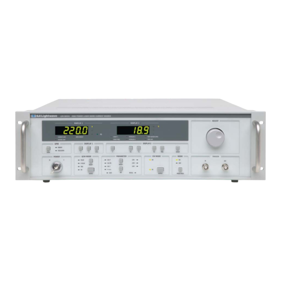
ILX Lightwave LDX-36000 Series User Manual (158 pages)
High Power Laser Diode Current Source
Brand:
ILX Lightwave
| Category:
Portable Generator
| Size: 2.16 MB
Table of Contents
Table of Contents
3
Safety Information and the Manual
11
General Safety Considerations
11
Safety Marking Symbols
13
Comments, Suggestions, and Problems
15
Chapter 1 Introduction and Specifications
17
Product Overview
18
Figure 1.1 LDX-36000 Series Front Panel
19
Figure 1.2 LDX-36000 Series Rear Panel, <50 a
19
Figure 1.3 LDX-36000 Series Rear Panel, >50 a
19
Installation
20
Initial Inspection
20
Grounding Requirements
20
AC Power Requirements
20
GPIB Communications
20
Tilt-Foot Adjustment
21
Shipping Kit
21
External Interlocks
21
Obtaining Repair Services
22
Options and Accessories
22
Table 1.1 Options and Accessories
22
Specifications
23
Table 1.2 LDX-36000 Series Specifications
25
Chapter 2 Safety
33
Laser Safety
34
Optical Safety
34
Safety Features and Compliance to Government Regulations
36
Laser Classification (as Appropriate)
36
Protective Housing (as Appropriate)
36
Laser Emission Indicators (as Appropriate)
36
Operating Controls (as Appropriate)
37
Location of Safety Labels
37
Figure 2.1 LDX-36000 Series Rear Panel Labels, <50 a
37
Figure 2.2 LDX-36000 Series Rear Panel Labels, >50 a
38
Chapter 3 Operation
39
Power-Up
39
Power-Up Sequence
39
Power-On State
40
Connections for General Operation
40
Table 3.1 LDX-36000 Series Default Configuration
40
Inductance
41
Figure 3.1 Laser and Photodiode Connections
42
Laser Current Source Output
42
Figure 3.2 LDX-36000 Output and Measurement Connector Pin
43
Figure 3.3 LDX-36000 Output and Measurement Connector Pin
43
External Interlocks
44
Figure 3.4 External Interlocks
44
Forward Voltage Measurement
44
External Photodiode Measurement
45
Grounding Considerations
45
Temperature Measurement
45
Front Panel Operation
46
The Adjust Knob
46
Display 1
46
Figure 3.5 Adjust Knob
46
Figure 3.6 Display 1
46
Display 2
47
Figure 3.7 Display 2
47
Temperature Measurement Setup
48
Table 3.2 Display Indicators
48
Table 3.3 Typical 10 Kw @ 25°C Thermistor Calibration Values
49
Limit Setup
50
Figure 3.8 Selecting Parameters
50
Configuring the Operational Mode
51
Adjusting Current Setpoint
51
Enabling CW Output
51
Figure 3.9 Mode Selection
51
Figure 3.10 CW Mode Box
51
QCW (Pulsed) Mode Setup
52
Table 3.4 Configuring QCW Parameters
52
Figure 3.11 QCW Current Ramp Enabling Output
53
Figure 3.12 QCW Current Ramp with Output Enabled
53
Figure 3.13 QCW Mode Box
54
QCW-Pulse Mode
54
QCW-Trig Mode
55
Figure 3.14 QCW Timing Diagram
56
Hard Pulse Mode
56
Automatic Shutoff Conditions for Current Output
57
Additional Functions and Features
57
Adjusting Current Setpoint in Terms of Optical Power
57
Figure 3.15 Determining Output Current Setpoint
58
Configuring External Photodiode Power Measurements
59
Adjustable Photodiode Bias
59
LIV Sweep Mode
59
Table 3.5 Automated L-I-V Mode GPIB Commands
60
Pulse out
61
Trigger in
61
Trigger out
61
Saving and Recalling from the Front Panel
62
Chapter 4 Remote Operation
63
Command Syntax
67
Letters
67
White Space
67
Table 4.1 Acceptable Spelling
67
Table 4.2 White Space
67
Terminators
68
Command Separators
68
Parameters
68
Table 4.3 Query Formatting
68
Table 4.4 Parameters
69
Table 4.5 Substitute Parameter Values
69
Command Tree Structure
70
Figure 4.4 Command Path Structure
70
Syntax Summary
71
Table 4.6 Invalid Syntax Command Strings
71
Figure 4.5 Common Command Diagrams
72
IEEE-488.2 Command Commands
72
Table 4.7 LDX-36000 IEEE Common Commands
73
LDX-36000 Commonly Used Commands
74
Table 4.8 LDX-36000 Commonly Used Commands
74
Status Reporting
76
Event Condition Registers
76
Operation Complete Definition
77
Figure 4.6 Status Reporting Scheme
77
Output off Register
78
Figure 4.7 Laser Output off Register
78
Table 4.9 Default Output off Register Settings
78
Command Timing
79
Sequential / Overlapped Commands
79
Query Response Timing
79
Chapter 5 Command Reference
81
Remote Command Reference Summary
82
Table 5.1 Remote Command Summary Reference List
82
Command Reference
87
Electrical Safety
33
Basic GPIB Concepts
63
Data and Interface Messages
63
Talkers, Listeners, and Controllers
64
GPIB Cable Connections
64
The GPIB Connector
64
Figure 4.1 GPIB Cable Connections
64
Figure 4.2 GPIB Connector Diagram
65
Reading the GPIB Address
66
Changing the GPIB Address
66
Changing Operation from Local to Remote
66
Figure 4.3 GPIB Local Button
66
Chapter 6 Calibration and Troubleshooting
140
Calibration Overview
140
Beginning Calibration
141
Laser Diode Current Setpoint Calibration
142
QCW Calibration
143
Laser Diode Voltage Measurement Calibration
144
Voltage Limit Setpoint
145
Photodiode Current (PDI) Measurement
146
Thermistor Calibration
147
Troubleshooting
149
Table 6.1 Symptoms and Corrective Actions
149
Error Messages
151
Table 6.2 Error Code Classifications
151
Table 6.3 Error Messages
152
Error
153
Appendix A Allowed QCW Space
156
Allowed QCW Operating Region
156
Allowed QCW Operating Region for 36125-24
158
Appendix B Allowed QCW Space - LDX-36125-24
158
Figure A.1 Allowed QCW Operating Region
158
Figure B.1 Allowed QCW Operating Region for LDX-36125-24
158
Advertisement
Advertisement
Related Products
ILX Lightwave LDX-36010-12
ILX Lightwave LDX-36050-12
ILX Lightwave LDX-36025-12
ILX Lightwave LDX-36125-12
ILX Lightwave LDX-36085-12
ILX Lightwave LDX-3620
ILX Lightwave LDX-3620B
ILX Lightwave LDX-3210
ILX Lightwave LDX-3412
ILX Lightwave LDX-3207
ILX Lightwave Categories
Controller
Temperature Controller
Portable Generator
Measuring Instruments
Control Unit
More ILX Lightwave Manuals
Login
Sign In
OR
Sign in with Facebook
Sign in with Google
Upload manual
Upload from disk
Upload from URL