Sign In
Upload
Manuals
Brands
ICS Manuals
Chiller
iC 305
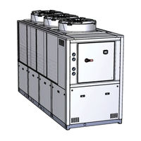
ICS iC 305 Industrial Water Chiller Manuals
Manuals and User Guides for ICS iC 305 Industrial Water Chiller. We have
1
ICS iC 305 Industrial Water Chiller manual available for free PDF download: Operating And Maintenance Manual
ICS iC 305 Operating And Maintenance Manual (72 pages)
Brand:
ICS
| Category:
Chiller
| Size: 1.53 MB
Table of Contents
- User's Quick Guide
2
Unit Start/Stop
2
Start from the Keypad
2
Start-Up from a Digital Input
2
Setpoint
3
Display the Setpoint
3
Change the Setpoint
3
Alarms Display and Reset
3
Table of Contents
4
Able of
4
General Information
7
Safety
8
General
8
User Circuit Liquids
8
Lifting and Transport Precautions
9
Precautions to be Adopted During Installation
10
Precautions to be Adopted During Operation
11
Maintenance Precautions
11
Refrigerant Gases
12
Refrigerants Safety Datasheet
12
Technical Data
14
Declaration of Conformity
15
Data for Standard Units
16
Dimensions
16
Characteristics of Pumps and Fans
16
Sound Level Measurements
18
Description
20
Components
20
Refrigerant Circuit
20
Compressors
20
Condenser
21
Evaporator
21
Tank
21
Pump
21
Fans
21
Axial
21
Axial for /HE Version (Only on High Efficiency Models, Where Envisaged)
22
High Pressure Axial Flow Fans
22
Centrifugal
22
Cabinet
22
Materials in Contact with the Liquid to be Cooled
22
Overall Dimensions and Minimum Clearances with Respect to Walls
22
Electrical Circuit
22
Sub-Zero Ambient Temperatures
23
Installation
24
Inspection
24
Location
24
Freeze Protection
25
Operating Limits
25
Hydraulic Connections
26
Expansion Vessel
27
Electrical Connections
28
Phase Monitor
29
Starting
30
Electronic Controller
32
User Interface
32
Function of Buttons
32
Function of Combined Buttons
33
Remote Terminal
33
Probes Key
33
Unit Start/Stop
34
Start from the Keypad
34
Start from a Digital Input
34
Setpoint
34
Display the Setpoint
34
Change the Setpoint
34
Dynamic Setpoint Function (with Anti-Freeze Heater Only)
35
How to Display the Internal Values of a Circuit
36
Functions Menu Button "Menu
36
Cren - Enable or Disable the Single Circuit
36
Coen - Enable or Disable the Single Compressor
37
Cosn - Display and Reset the Number of Compressor Starts
37
Hour - Display and Reset the Running Hours of the Loads
37
Cond - Display of Percentage / Number of Condensing Steps
38
Tank Heater Probe Display
38
Alarms
38
Alarms Display and Reset (Alrm Function)
38
7 . 1 1 . 2 H O W T O M U T E T H E B U Z Z E R
39
7 . 1 1 . 3 G E N E R a L a L a R M S L I S T
39
7 . 1 1 . 4 I N D I C a T I O N S T a B L E
40
7 . 1 1 . 5 P R O B E F a U L T y
40
7 . 1 1 . 6 H I G H P Re S S U R E S W I T C H a L a R M
40
7 . 1 1 . 7 H I G H P R E S S U R E S W I T C H a L a R M a N D / O R C O M P R E S S O R T H E R M a L a L a R M
41
7 . 1 1 . 8 L O W P R E S S U R E S W I T C H a L a Rm
41
7 . 1 1 . 9 H I G H P Re S S U R E
41
Low Pressure
41
Anti-Freeze Alarm
41
Chiller Mode Anti-Freeze Alarm
42
Water Differential Pressure Switch Alarm
42
Compressors Thermal Alarm
42
Fan Thermal Alarm
43
High Condensing Pressure Unloading Indication in Chiller Mode
43
High Condensing Pressure Recovery Disabling Indication in Chiller Mode
43
Evaporator Inlet High Water Temperature Unloading Indication
43
Evaporator Water Pump Group Thermal Alarm
43
Phase Monitor Alarm
44
Compressors Maintenance Alarm
44
Pumps Maintenance Alarm
44
Eeprom Alarm
44
Remote Terminal Alarm
44
Remote Terminal Alarm
45
Alarm Relay / Open - Collector / Buzzer Notes
45
Display and Delete the Alarms Log in the Memory (ALOG Function)
45
Programming from Keypad
45
Access to Parameters
46
How to Change a Parameter Value
47
Use of the Hot-Key (Function UPL)
47
Programming the Board with the Hot-Key
47
Hot-Key Programming
47
Unit Adjustment and Control
47
7.14.1 Compressors Control
47
Choice of Compressors Control Type
47
Proportional Control
47
Compressors Proportional Control Diagram
48
Neutral Zone Control (Factory Setting)
48
Compressors Rotation
48
Forced Compressors Rotation
48
Compressors Starting Time Limitation
49
Unloading Function
49
Anti-Freeze Heaters
49
Fans Control
49
Units Configured with "STEP" Fans
49
Units Configured with Fan Speed Control
50
Fan Control Diagrams
50
Hydraulic Unit
50
Anti-Freeze Pump Management (if Ambient Probe Is Installed)
51
Modbus
51
Automatic Restart
51
Parameters Description-Settings
51
Description of Parameters
51
7 . 2 2 . 2 P a R a M E T E R S S E T T I N G
55
7 . 2 2 . 3 P a R a M E T E Rs D E P E N D E N T O N R E M O T E T E R M I N a L K I T
56
Other Components
57
Compressor Motor Protection
57
Refrigerant High and Low Pressure Switches
57
Fan Pressure Switches (Models IC 215÷540)
57
Electronic Thermostatic Valve (Optional)
58
Pressure Transducers
58
Level Sensor
59
Operation and Maintenance
60
Operation
60
Maintenance
60
Access to the Unit
60
Draining the Process Water Circuit
61
Maintenance Schedule
62
Troubleshooting
63
Isk Analysis : Residual Risk
69
Advertisement
Advertisement
Related Products
ICS iC 303
ICS iC 220
ICS iC 412
ICS iC 520
ICS iC 530
ICS iC 535
ICS iC 538
ICS iC 640
ICS iC 660
ICS iC 770
ICS Categories
Chainsaw
Saw
Measuring Instruments
Computer Hardware
Controller
More ICS Manuals
Login
Sign In
OR
Sign in with Facebook
Sign in with Google
Upload manual
Upload from disk
Upload from URL