Sign In
Upload
Manuals
Brands
IBM Manuals
Network Storage Server
SAN512B-6
IBM SAN512B-6 Manuals
Manuals and User Guides for IBM SAN512B-6. We have
1
IBM SAN512B-6 manual available for free PDF download: Installation, Service And User Manual
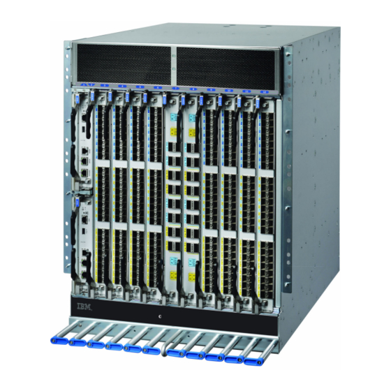
IBM SAN512B-6 Installation, Service And User Manual (286 pages)
IBM Storage Networking
Brand:
IBM
| Category:
Network Storage Server
| Size: 17.38 MB
Table of Contents
Table of Contents
5
Figures
9
Tables
11
Accessibility Features
13
Getting Help
13
Read this First
13
How to Send Your Comments
14
Cautions
15
Safety and Environmental Notices
15
Safety Notices and Labels
15
Danger Notices
17
Safety Labels
20
Attention Notices
22
Environmental Notices
22
ESD Precautions
22
Rack Safety
22
About this Document
23
Brocade Documents
23
Product Documents
23
IBM and Brocade Product Matrix
24
Brocade and IBM Product and Model Number Matrix
24
Chapter 1. Introducing the SAN512B-6
25
Product Features
25
Hardware Components
26
Port-Side View of Device
27
Port Side of the SAN512B-6
28
Port-Side Slot Numbering
29
Nonport-Side View of the Device
29
Nonport Side of the SAN512B-6
30
Chapter 2. Preparing for the Installation
31
Safety Precautions
31
Lifting Precautions
33
Facility Requirements
34
Time and Items Required for Installation
35
Installation Tasks, Time, and Items Required
36
Quick Installation Checklists
37
Installation and Basic System Configuration
37
Items Shipped
39
Chapter 3. Mounting the Device
41
Mounting Options
41
Mounting Precautions
41
Unpacking and Transporting the Device
43
Port-Side Slot Numbering
44
Installing the 14U Rack Mount Kit for Four-Post Racks
44
Time and Items Required
44
Refer to "Installing the 14U Rack Mount Kit for Four-Post Racks
44
Parts List
45
Parts List - NEBS Kit
46
Rack Kit Parts
46
Assembling the Rack Hardware
47
NEBS Kit Parts List
47
Left and Right Shelf Brackets Installed on Rails
48
Nut and Screw Locations for Mounting the Device
49
Installing the Device in the Rack
50
Positioning the Device for Installation in a Rack
51
Installing the 14U Chassis MID-Mount Rack Kit for Two-Post Racks
52
Time and Items Required
52
Attaching Port Side of Device to Rack Rails
52
Parts List
53
Assembling the Rack Hardware
54
Rack Kit Parts
54
Attaching the Rear Tray to the Rack Rails
55
Installing the Device in the Rack
56
Attaching the Front Tray to the Rack Rails
56
Removing the Protective Cover
58
Attaching Trays to the Device
58
Removing Protective Cover from SAN512B-6
59
Caution
59
Chapter 4. Initial Setup and Verification
61
Configuration and Verification Task Guide
61
Configuration
61
Configuration and Verification Tasks
61
Items Required
62
Providing Power to the Device
63
Connecting Power Cord to AC Power Supplies
63
Connecting Power Cord to HVAC/HVDC Power
64
Supplies
64
Establishing a Serial Connection to the Device
70
Configuring the IP Addresses
72
Establishing an Ethernet Connection to the Device
73
Port
73
Setting the Domain ID
74
Setting the Date and Time
74
Setting the Time Zone
75
Synchronizing Local Time with an External Source
76
Example: Tstimezone Command Parameter Selection for the US Time Zones
76
Customizing the Chassis and Switch Name
77
Veifying the PID Mode
77
Verifying Installed Licenses and License Key
78
Verifying Correct Operation
78
Backing up the Configuration
79
Powering down the Chassis
80
Chapter 5. Installing Transceivers and Cables
81
Supported Transceivers and Cables
81
Blade
81
Core Routing Blades
82
QSFP Transceiver with Separate Cable
82
Km QSFP 16 Gbps with Integrated Cable
83
Time and Items Required
84
Km LWL QSFP Transceiver with Integrated Cable
84
Female-To-Female Patch Cable for QFSP
84
Precautions Specific to Transceivers and Cables
85
Cleaning the Fiber-Optic Connectors
85
Optical Transceiver Extraction Tool
85
Cable Management
86
Installing an SFP+ Transceiver
86
Installing an SFP+ Transceiver with Pull Tab
87
Installing an SFP+ Transceiver with Bail Latch
87
Replacing an SFP+ Transceiver
88
Replacing a SFP+ Optical Transceiver with Pull Tab into Blade Port
88
Installing a QSFP Transceiver
89
Installing an SFP+ Transceiver with Bail Latch
89
Replacing a QSFP Transceiver
90
Installing a QSFP Transceiver into Blade Port
90
Installing a QSFP Optical Transceiver into Blade
91
Verifying the Operation of New Transceivers
92
Chapter 6. Monitoring the Switch
93
Interpreting Port Blade Leds
93
FC32-48 Port Blade Leds
94
Port Blade LED Descriptions
94
Interpreting Extension Blade Leds
96
SX6 Extension Blade Leds
96
Extension Blade LED Descriptions
97
Interpreting Control Processor Blade Leds
98
CP Blade LED Descriptions
99
Interpreting Core Routing Blade Leds
101
CR32-8 Core Routing Blade Leds
101
Interpreting WWN Card Leds
102
Core Routing Blade LED Descriptions
102
Interpreting Power Supply Leds
103
WWN Card LED Descriptions
103
Interpreting Fan Assembly Leds
106
Fan Assembly Leds
107
Fan Assembly LED Descriptions
107
Interpreting POST and Boot Results
108
Post
108
Boot
109
Using Monitoring Commands
109
Chassisshow
110
Errdump and Errshow
113
Fanshow
114
Hashow
114
Historyshow
115
Psshow
116
Sensorshow
116
Slotshow
116
Sfpshow
117
Switchshow
123
Supportsave
124
Tempshow
125
Running Diagnostic Tests
127
Chapter 7. Port and Extension Blades
129
Port Blade Overview
129
FC32-48 Blade Port Numbering and Trunking
129
FC32-48 Blade Port Numbering
130
Extension Blade Overview
131
Extension Features
132
SX6 Blade Port Numbering and Trunking
133
SX6 Extension Blade Port Numbering
133
Precautions Specific to the Blade
134
Faulty Blade Indicators
135
Time and Items Required for Removal and Installation
135
Removing a Blade
135
Removing and Replacing Port or Extension
137
Installing a Blade
138
Verifying Blade Operation
139
Chapter 8. Core Routing Blades
141
Core Routing Blade Overview
141
CR32-8 Port Numbering
141
Connections
141
CR32-8 Core Routing Blade Port Numbering
142
ICL Trunking Groups
143
External Port to Slotshow Port Mapping for Core Blades
143
ICL Cabling Configurations
144
ICL Cable Connections (Sample Configuration)
145
Precautions Specific to the Blade
146
Faulty Core Routing Blade Indicators
147
Removing a Core Routing Blade
148
Removing and Installing a Core Routing Blade
150
Time and Items Required
148
Installing a Core Routing Blade
151
Verifying Blade Operation
152
Chapter 9. Control Processor Blades
153
Control Processor Blade Overview
153
CPX6 Port Identification
154
CPX6 Blade Port Identification
154
Precautions Specific to the Blade
155
Blade Fault Indicators
155
Blade Replacement Task Guide
156
Time and Items Required for Replacement
157
Preparing for Replacement
157
Replacing a CP Blade
158
Hot-Swap Procedure
159
Removal and Replacement of the Control Processor Blade (CPX6)
160
Cold-Swap Procedure
165
Removal and Replacement of the Control Processor Blade (CPX6)
166
Completing the Replacement
167
Verifying Blade Operation
168
Chapter 10. WWN Cards
171
WWN Card Overview
171
WWN Card Location and Numbering
171
Precautions Specific to WWN Cards
172
WWN Card Fault Indicators
172
WWN Card Location and Numbering
172
Messages that May Indicate WWN Card
173
WWN Card Replacement Task Guide
174
Time and Items Required for Replacement
174
Using the Wwnrecover Utility
175
Raslog Messages from WWN Card Audit
175
Preparing for WWN Card Replacement
176
Hot-Swap Replacement
177
Cold-Swap Replacement
178
Removing the WWN Card and Bezel
180
Configuring Airflow Direction on WWN Cards
181
Removing and Installing WWN Cards
181
Verifying WWN Card Operation
183
Chapter 11. Power Supply Assemblies
185
AC Power Supply Overview
185
Fan and Power Supply Airflow
186
Airflow Labels
186
Power Supply Assembly Numbering
187
HVAC/HVDC Power Supply Overview
188
HVAC/HVDC Power Supply Assembly
189
Precautions Specific to Power Supply Assembly
190
Power Supply Assembly Fault Indicators
190
HVAC/HVDC Power Cable
190
Power Supply Assembly Task Guide
191
Time and Items Required
192
Removing a Power Supply
192
Installing a Power Supply
193
Removing and Installing Power Supply Assembly
193
Verifying Power Supply Operation
194
Chapter 12. Fan Assemblies
197
Fan Assembly Overview
197
Fan and Power Supply Airflow
198
Fan Assembly
198
Airflow Labels
199
Fan Assembly Numbering
200
Precautions Specific to Fan Assemblies
200
Fan Assembly Fault Indicators
201
Fan Assembly Task Guide
201
Time and Items Required
202
Removing a Fan Assembly
202
Installing a Fan Assembly
203
Removing and Installing a Fan Assembly
203
Verifying Fan Operation
204
Chapter 13. Blade Filler Panels
205
Blade Filler Panel Removal and Replacement
205
Removing a Filler Panel
205
Installing a Filler Panel
206
Removing and Installing the Blade Filler Panel
206
Removing and Installing the Blade Filler Panel
207
Chapter 14. Cable Management Comb
209
Cable Management Comb Overview
209
Time and Items Required for Removal and Installation
209
Removing Cable Management Comb
209
Installing Cable Management Comb
210
Removing or Installing Cable Management
210
Chapter 15. Chassis Door
211
Chassis Door Overview
211
Time and Items Required
211
Removing a Chassis Door
211
Installing a Chassis Door
212
Removal and Replacement of the Chassis Door
212
Removing Protective Cover from SAN512B-6 Chassis
213
Removal and Replacement of the Chassis Door
214
Chapter 16. Replacing the Chassis
215
Chassis Replacement Overview
215
Precautions Specific to Chassis Replacement
215
Configuration
215
Chassis Replacement Task Guide
216
Customer Replacement Responsibilities
217
Critical Information Checklist
219
IBM Service Replacement Responsibilities
227
Chapter 17. Removing the Battery
231
Location of Battery Holder
231
Appendix A. SAN Rack
233
Installing the IBM SAN Rack
233
Step 1. Position the Rack
234
Step 2. Level the Rack
234
Caster Wheel
234
Step 3. Attach the Stabilizers
235
Adjusting the Leveling Feet
235
Step 4. Attach the Rack to a Concrete Floor
236
Attaching the Rack to a Concrete Floor
236
Beneath a Raised Floor
238
Leveling the Rack
238
Step 5. Attach the Rack to a Concrete Floor Beneath a Raised Floor
238
Attaching the Rack to a Raised Floor
239
Step 6. Attach the Mounting Plates
241
Step 7. Attach the Front Door
241
Attaching the Mounting Plate
241
Step 8. Check the Customer's Ac Power Source
242
Attaching the Front Door
242
Step 9. Check the Intelligent Power Distribution Units
243
Step 10. Connect Switch and Device Cables
245
Step 11. Power on the Rack
245
Power Cord Cabling (Rack Side View)
245
Service Procedures
246
Director Power-Off Procedure
246
Removing and Replacing the Ipdus
247
SAN Rack with Ipdu Locations
247
Removing and Replacing the Front or Rear Rack
248
Door
249
Relocating the Rack
249
Removing the Rack Door
249
Parts Information
250
Power Cables for Side-Mount Ipdus
255
Items Supplied with the 14U Director Chassis Mount Kit
255
Ipdu Locations
256
SAN Rack Specifications
257
Ipdu (PN 00FW787) for Director Attachment
257
IBM SAN Rack Specifications
257
Appendix B. Product Specifications
259
Environmental Requirements
265
Notices
275
Electronic Emission Notices
276
Federal Communications Commission Statement
276
Industry Canada Compliance Statement
277
Australia and New Zealand Class a Statement
277
European Union Electromagnetic Compatibility Directive
277
Germany Electromagnetic Compatibility Directive
278
People's Republic of China Class a Statement
280
Taiwan Class a Statement
280
Taiwan Contact Information
280
Japan Voluntary Control Council for Interference Class a Statement
280
Japan Electronics and Information Technology Industries Association Statement
281
Korean Communications Commission Class a Statement
281
Russia Electromagnetic Interference Class a Statement
282
Homologation Statement
276
Trademarks
276
Index
283
Advertisement
Advertisement
Related Products
IBM SAN06B-R
IBM SAN256B-6
IBM SAN50C-R
IBM SAN04B-R - System Storage Router
IBM 2498B24 - System Storage SAN24B-4 Switch
IBM SAN40B-4 - System Storage Switch
IBM SAN32M1
IBM SAN384B
IBM SAN24B-6
IBM SAN768C-6
IBM Categories
Server
Desktop
Storage
Laptop
Monitor
More IBM Manuals
Login
Sign In
OR
Sign in with Facebook
Sign in with Google
Upload manual
Upload from disk
Upload from URL