Sign In
Upload
Manuals
Brands
Hypertherm Manuals
Welding System
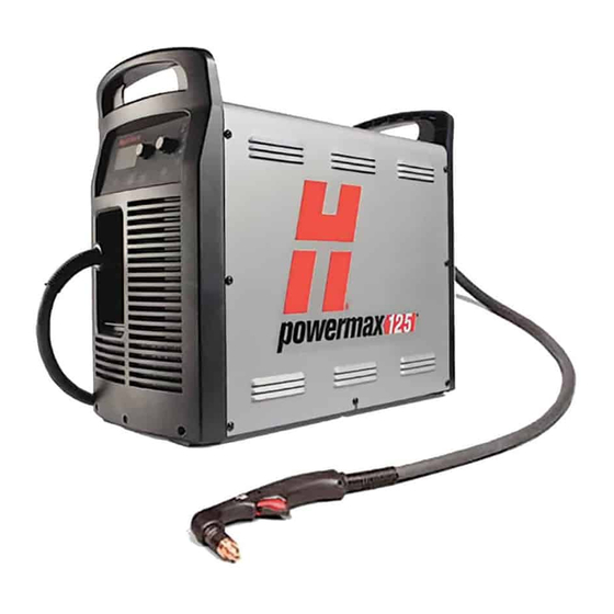
Powermax 125
User Manuals: Hypertherm Powermax 125 Plasma Cutter
Manuals and User Guides for Hypertherm Powermax 125 Plasma Cutter. We have
4
Hypertherm Powermax 125 Plasma Cutter manuals available for free PDF download: Service Manual, Field Service Bulletin
Hypertherm Powermax 125 Service Manual (317 pages)
Plasma Arc Cutting System
Brand:
Hypertherm
| Category:
Welding System
| Size: 18.11 MB
Table of Contents
Table of Contents
7
Electromagnetic Compatibility (EMC
15
Assessment of Area
15
Installation and Use
15
Introduction
15
Methods of Reducing Emissions
15
Mains Supply
15
Cutting Cables
16
Earthing of the Workpiece
16
Equipotential Bonding
16
Maintenance of Cutting Equipment
16
Screening and Shielding
16
Attention
17
General
17
Warranty
17
Insurance
18
Liability Cap
18
Limitation of Liability
18
National and Local Codes
18
Patent Indemnity
18
Transfer of Rights
18
Specifications
19
Safety Information
19
Powermax125 System Description
19
Power Supply Dimensions
20
Component Weights (125 a Systems)
21
Hypertherm Power Supply Ratings
22
Contents
23
Duramax Hyamp 85° Hand Torch Dimensions
23
Duramax Hyamp 15° Hand Torch Dimensions
23
Duramax Hyamp 180° Full-Length Machine Torch Dimensions
24
Duramax Hyamp 180° Mini Machine Torch Dimensions
24
Powermax125 Cutting Specifications
25
Symbols and Markings
26
Noise Levels
27
IEC Symbols
28
Power Supply Setup
29
Unpack the Powermax System
29
Claims
29
Contents
30
Position the Power Supply
30
Prepare the Electrical Power
31
Install a Line-Disconnect Switch
31
Requirements for Grounding
31
Power Connection for the Powermax125
32
Three-Phase Power Cord and Plug Installation
33
Decrease Output Current for Lower-Rated Power Plugs
33
Extension Cord Recommendations
35
Engine-Driven Generator Recommendations
35
Prepare the Gas Supply
36
Additional Gas Filtration
36
Connect the Gas Supply
37
Gas Flow Rates
38
Minimum Inlet Pressure (While Gas Is Flowing)
38
Basic System Operations
39
Controls and Indicators
39
Rear Controls
39
Front Controls and Leds
40
Leds
40
Selectors
40
Amperage Adjustment Knob
41
Operating Mode Switch
41
Status Screen
41
Fault Codes and Icons
42
Gas Pressure Indicators
42
System Status Icons
42
Powermax125 Service Manual
43
Operating the Powermax
44
Connect the Electrical Power, Gas Supply, and Torch Lead
44
Attach the Work Lead to the Power Supply
45
Attach the Ground Clamp to the Workpiece
46
Turn on the System
46
Check the Indicators
47
Set the Operating Mode Switch
47
Adjusting the Current (Amperage)
48
Manually Adjusting the Gas Pressure
48
Electrode End-Of-Life Detection Feature
49
Understanding Duty-Cycle Limitations
50
Hand Torch Setup
51
Introduction
51
Consumable Life
51
Hand Torch Components
52
Duramax Hyamp 85° Hand Torch
52
Duramax Hyamp 15° Hand Torch
52
Choose the Hand Torch Consumables
52
Drag-Cutting 105/125 a Consumables
53
Drag-Cutting 45 a and 65 a Consumables
53
Finecut Consumables
53
Gouging Consumables
53
Install the Hand Torch Consumables
54
Connecting the Torch Lead
55
Hand Cutting
57
Using the Hand Torch
57
Operate the Safety Trigger
58
Hand Torch Cutting Guidelines
58
Start a Cut from the Edge of the Workpiece
59
Pierce a Workpiece
60
Gouge a Workpiece
62
Gouge Profile
63
Varying the Gouge Profile
64
125 A Gouging Profile Chart
64
Common Hand-Cutting Faults
66
Contents
67
Machine Torch Setup
67
Introduction
67
Consumable Life
67
Machine Torch Components
68
Duramax Hyamp 180° Machine Torch
68
Duramax Hyamp 180° Mini Machine Torch
68
Disassemble the Machine Torch
69
Convert a Full-Length Machine Torch to a Mini Machine Torch
71
Mount the Torch
72
Choose the Machine Torch Consumables
73
Machine Torch Consumables
73
Mechanized Shielded 105 A/125 a Consumables
73
Mechanized Shielded 45 a and 65 a Consumables
73
Mechanized Shielded with Ohmic 105 A/125 a Consumables
74
Mechanized Shielded with Ohmic 45 a and 65 a Consumables
74
Gouging Consumables
74
Finecut Shielded Consumables
74
Finecut Shielded with Ohmic Consumables
75
Install the Machine Torch Consumables
75
Aligning the Torch
75
Connecting the Torch Lead
76
Using the Cut Charts
77
Estimated Kerf-Width Compensation
78
Estimated Kerf-Width Compensation - Metric (MM)
78
Estimated Kerf-Width Compensation - English (Inches)
79
125 A Shielded Consumables
80
125 A Shielded Cutting - Mild Steel
81
125 A Shielded Cutting - Stainless Steel
82
125 A Shielded Cutting - Aluminum
83
105 A Shielded Consumables
84
105 A Shielded Cutting - Mild Steel
85
105 A Shielded Cutting - Stainless Steel
86
105 A Shielded Cutting - Aluminum
87
65 A Shielded Consumables
88
65 A Shielded Cutting - Mild Steel
89
65 A Shielded Cutting - Stainless Steel
90
65 A Shielded Cutting - Aluminum
91
45 A Shielded Consumables
92
45 A Shielded Cutting - Mild Steel
93
45 A Shielded Cutting - Stainless Steel
94
45 A Shielded Cutting - Aluminum
95
Finecut Consumables
96
Powermax125 Service Manual
96
Finecut - Mild Steel
97
Finecut - Stainless Steel
98
Mechanized Cutting
99
Connecting an Optional Remote-Start pendant
99
Connecting the Machine Interface Cable
100
Machine Interface Pinout
102
Setting the Five-Position Voltage Divider
103
Accessing Raw Arc Voltage
104
Connecting an Optional RS-485 Serial Interface Cable
104
Serial Port Cables
105
Using the Machine Torch
105
Setting up the Torch and Table
105
Understand and Optimize Cut Quality
105
Cut or Bevel Angle
106
Dross
106
Piercing a Workpiece Using the Machine Torch
107
Common Machine-Cutting Faults
107
Troubleshooting and System Tests
109
Controls and Indicators
109
Rear Panel
109
Front Panel
110
Status Screen
110
Theory of Operation
111
400 V CE, 380 V CCC 3-Phase Power Supply Functional Description
111
480 V and 600 V CSA 3-Phase Power Supply Functional Description
111
Sequence of Operation
112
Troubleshooting Preparation
113
Test Equipment
113
Troubleshooting Procedures and Sequence
113
External Inspection
115
Internal Inspection
115
Initial Resistance Check
115
Check the Power Switch
115
Hypertherm IGBT Tester
118
IGBT Test Preparation
119
Indicator Leds and Device Tests
119
IGBT Device Test Using the Hypertherm Tester
121
Troubleshoot the Hypertherm IGBT Tester
121
Contents
122
IGBT Device Test Using a Non-Hypertherm Tester
122
Fault Codes
128
Important Fault Icons
128
Displaying the Service Screen
128
Run a Gas Test
130
Perform a Cold Restart
131
Fault Codes and Solutions
131
Fault Code Format - 0-00-0
131
Fault Code Format - 0-Nn-N
132
Fault Code Format - 1-Nn-N
138
Fault Code Format - 2-Nn-N
138
Fault Code Format - 3-Nn-N
139
Torch-Related Faults - Continuity Check
142
Troubleshooting Guide
143
System Tests
149
Test 1 - Voltage Input
150
Test 2 - DC Power Bus
152
Resistance Check
152
Voltage Check
152
Test 3 - Output Diodes
154
Test 4 - Inverter Temperature Sensor
154
For Operational Fault Codes 0-40-2 and 0-40-3 or Power Board Faults 2-10-0 and 2-10-1
155
Test 5 - Flyback Circuit (DC Minor Voltages)
156
Test 6 - Torch Stuck Open/Torch Stuck Closed
158
Test 7 - Start Signal
160
Test 8 - Torch Cap Switch
161
Test 9 - Electronic Regulator
162
Test 10 - Pressure Sensor
163
Test 11 - Fan
164
Test 12 - aux Switch
164
Power Supply Component Replacement
165
Installing a Machine Interface Cable for Raw Arc Voltage
166
Disconnect the Power and Gas Supply
166
Replacing the Gas Filter Element
167
Replacing the Work Lead Connector
169
Installing the Optional Filter Kit
170
Replacing the Power Supply Cover
172
Replacing the Component Barrier
173
Replacing the End Panel Bracket
174
Powermax125 Service Manual
175
Replacing the Machine Interface Cable with Voltage Divider Board
176
Set the Voltage Divider Board
181
Installing the Machine Interface Cable
182
Installing the RS-485 Serial Interface Cable
183
Replacing the Power Cord and Strain Relief
190
Replacing the Power Switch
197
Replacing the Control Board
201
Replacing the DSP Board
203
Replacing the Power Board
205
Replacing the Input Diode Bridge
209
Replacing the Output Diode Bridge
210
Replacing the Pilot Arc IGBT
211
Replacing the Inverter IGBT Module
212
Replacing the Snubber Resistor
213
Replacing the Thermal Sensor
214
Replacing the Fan Shroud
216
Replacing the Fan
217
Replacing the Pressure Transducer
219
Replacing the Pressure Switch
221
Replacing the Gas Filter Assembly
223
Replacing the Solenoid Valve
225
Replacing the Gas Tubing
227
Replacing the Bulk Capacitors
229
Replacing the Torch Quick Disconnect Receptacle
231
Replacing the Work Lead Receptacle
236
Replacing the Output Inductor
238
Replacing the Transformer
244
Replacing the PFC Inductor
249
Replacing the Front Panel
252
Replacing the Rear Panel
257
Torch Component Replacement
265
Disconnect the Power, Gas Supply, and Torch
266
Hand Torches
267
Replacing the Handle
269
Replacing the Trigger Assembly
274
Replacing the Torch Body
276
Replacing the Start Switch
278
Replacing the Cap-Sensor Switch
280
Replacing the Torch Lead
281
Contents
284
Machine Torches
284
Replacing the Mounting Sleeve
285
Replacing the Cap Sensor Switch
287
Replacing the Torch Body
288
Replacing the Coupler and Positioning Sleeve (Full-Length Only) or Adapter (Mini Only)
289
Replacing the Torch Lead
290
Replacing the Quick Disconnect Housing
291
Parts
293
Power Supply Parts
294
Exterior, Front
294
Exterior, Rear
295
Interior, Power Board Side
297
480 V, 600 V Csa
297
400 V Ce/380 V CCC
298
Interior, Fan Side
299
Interior, Heatsink Assembly
300
Duramax Hyamp 85° Hand Torch Replacement Parts
301
Duramax Hyamp 15° Hand Torch Replacement Parts
302
Hand Torch Consumables
303
Drag Cutting
303
Gouging
303
Finecut
303
Duramax Hyamp 180° Full-Length Machine Torch Replacement Parts
304
Duramax Hyamp 180° Mini Machine Torch Replacement Parts
305
Machine Torch Consumables
306
Shielded
306
Gouging
306
Finecut
307
Accessory Parts
307
Powermax125 Labels
308
Safety-Critical Parts
310
Power Supply, Power Board Side
310
Power Supply, Fan Side
312
Recommended Spare Parts
313
Wiring Diagrams
315
Powermax Generic Timing Chart
316
Powermax125 Schematic Diagram
317
Advertisement
Hypertherm Powermax 125 Field Service Bulletin (40 pages)
Machine Interface Receptacle with Voltage Divider PCB
Brand:
Hypertherm
| Category:
Welding System
| Size: 5.57 MB
Hypertherm Powermax 125 Field Service Bulletin (20 pages)
Brand:
Hypertherm
| Category:
Welding System
| Size: 1.43 MB
Advertisement
Hypertherm Powermax 125 Field Service Bulletin (13 pages)
Wheel Kit Operation
Brand:
Hypertherm
| Category:
Welding System
| Size: 1.05 MB
Advertisement
Related Products
Hypertherm Powermax 1100
Hypertherm Powermax 1650
Hypertherm Powermax 1000
Hypertherm Powermax 1250
Hypertherm Powermax 105
Hypertherm Powermax 105 SYNC
Hypertherm powermax1250
Hypertherm powermax1650
Hypertherm Powermax125
Hypertherm Powermax1100
Hypertherm Categories
Welding System
Cutter
Flashlight
Industrial Equipment
Controller
More Hypertherm Manuals
Login
Sign In
OR
Sign in with Facebook
Sign in with Google
Upload manual
Upload from disk
Upload from URL