Sign In
Upload
Manuals
Brands
Hypertherm Manuals
Cutter
HyPerformance Plasma HPR260
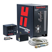
Hypertherm HyPerformance Plasma HPR260 Manuals
Manuals and User Guides for Hypertherm HyPerformance Plasma HPR260. We have
3
Hypertherm HyPerformance Plasma HPR260 manuals available for free PDF download: Instruction Manual, Field Service Bulletin
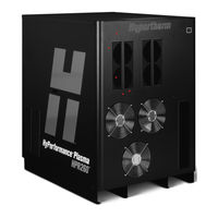
Hypertherm HyPerformance Plasma HPR260 Instruction Manual (251 pages)
for cutting mild steel, stainless steel and aluminum
Brand:
Hypertherm
| Category:
Cutter
| Size: 29.54 MB
Table of Contents
English
9
Electromagnetic Compatibility (EMC
5
Warranty
7
Table of Contents
9
Safety
15
Recognize Safety Information
16
Follow Safety Instructions
16
Cutting Can Cause Fire or Explosion
16
Electric Shock Can Kill
17
Static Electricity Can Damage Circuit Boards
17
Toxic Fumes Can Cause Injury or Death
18
A Plasma Arc Can Cause Injury and Burns
19
Arc Rays Can Burn Eyes and Skin
19
Grounding Safety
19
Compressed Gas Equipment Safety
20
Gas Cylinders Can Explode if Damaged
20
Noise Can Damage Hearing
20
Pacemaker and Hearing Aid Operation
20
A Plasma Arc Can Damage Frozen Pipes
20
Additional Safety Information
20
Warning Labels
22
Français
23
Section 1A
23
Sécurité
23
Identifier Les Consignes de Sécurité
24
Suivre Les Instructions de Sécurité
24
Le Coupage Peut Provoquer un Incendie Ou Une Explosion
24
Les Chocs Électriques Peuvent Être Fatals
25
L'électricité Statique Peut Endommager Les Cartes de Circuits Imprimés
25
Les Vapeurs Toxiques Peuvent Provoquer des Blessures Ou la Mort
26
L'arc Plasma Peut Provoquer des Blessures Ou des Brûlures
27
Les Rayons de L'arc Peuvent Brûler Les Yeux Et la Peau
27
Mise À la Masse Et À la Terre
27
Sécurité des Bouteilles de Gaz Comprimé
28
Les Bouteilles de Gaz Comprimé Peuvent Exploser en Cas de Dommages
28
Le Bruit Peut Provoquer des Problèmes Auditifs
28
Pacemakers Et Prothèses Auditives
28
Un Arc Plasma Peut Endommager Les Tuyaux Gelés
28
Étiquettes de Sécurité
30
Español
31
Seguridad
31
Section 1B SEGURIDAD
31
Reconocimiento de Información de Seguridad
32
Siga las Instrucciones de Seguridad
32
Los Cortes Pueden Provocar Incendios O Explosiones
32
El Choque Eléctrico Puede Provocar la Muerte
33
Electricidad Estática Puede Dañar Tablillas de Circuito
33
Humos Tóxicos Pueden Causar Lesiones O Muerte
34
El Arco de Plasma Puede Causar Lesiones y Quemaduras
35
Los Rayos del Arco Pueden Producir Quemaduras en Los Ojos y en la Piel
35
Seguridad de Toma a Tierra
35
Seguridad de Los Equipos de Gas Comprimido
36
Los Cilindros de Gas Pueden Explotar si Están Dañados
36
El Ruido Puede Deteriorar la Audición
36
Operación de Marcapasosy de Audífonos
36
Un Arco Plasma Puede Dañar Tubos Congelados
36
Etiquetas de Advertencia
37
Specifications
39
Section 2 SPECIFICATIONS
39
System Description
41
General
41
Power Supply
41
Ignition Console
41
Gas Console
41
Off-Valve Assembly
41
Torch
41
Off-Valve
41
Specifications
42
System Gas Requirements
42
Power Supply
43
Ignition Console - 078172
44
Gas Console - 078170
46
Off-Valve - 129816
47
Torch - 128818
48
Installation
49
Section 3 INSTALLATION
49
Upon Receipt
51
Claims
51
Installation Requirements
51
Noise Levels
51
Placement of System Components
51
Torque Specifications
51
Installation Requirements
52
System Components
53
Cables and Hoses
53
Supply Gas Hoses
53
Customer Supplied Power Cable
53
Recommended Grounding and Shielding Practices
54
Introduction
54
Types of Grounding
54
Steps to Take
55
Placement of the Power Supply
59
Install the Ignition Console
60
Placement of the Gas Console
62
Install the Off-Valve
63
Power Supply to Ignition Console Leads
64
Pilot Arc Lead
64
Negative Lead
64
Ignition Console Power Cable
66
Ignition Console Coolant Hoses
67
Power Supply to Gas Console Cables
68
Control Cable
68
Power Cable
68
Gas Console to Off-Valve Connections
70
Cable and Gas Hose Assembly
70
Gas Console to Off-Valve Cable
70
Off-Valve Cable
70
Power Supply to CNC Interface Cable
72
Optional Multi-System CNC Interface Cable
72
Notes to CNC Interface Cable Run List
73
Examples of Output Circuits
74
Examples of Input Circuits
75
Remote On/Off Switch
76
Torch Lead Assembly
77
Work Lead
78
Torch Connections
79
Connect the Torch to the Torch Lead Assembly
79
Connect the Torch to the Quick-Disconnect
82
Torch Mounting and Alignment
83
Mounting the Torch
83
Torch Alignment
83
Torch Lifter Requirement
83
Power Requirements
84
General
84
Line Disconnect Switch
84
Power Cable
84
Connect the Power
85
Torch Coolant Requirements
86
Standard Installation
86
Coolant for Cold Operating Temperatures
87
Coolant for Hot Operating Temperatures
88
Water Purity Requirements
88
Fill the Power Supply with Coolant
89
Gas Requirements
90
Setting the Supply Regulators
90
Gas Regulators
91
Supply Gas Plumbing
92
Connect the Supply Gases
92
Supply Gas Hoses
93
Operation
94
Section 4 OPERATION
94
Daily Start-Up
95
Check Torch
95
Controls and Indicators
96
General
96
Main Power Switch
96
Power Indicators
96
Manual Gas Console Operation
97
Consumable Selection
98
Mild Steel
98
Stainless Steel
99
Aluminum
99
Install Consumables
100
Cut Charts
101
Bevel Cutting
101
Marking
101
Consumables for Mirror-Image Cutting
101
Estimated Kerf Width Compensation
102
Changing Consumable Parts
126
Remove Consumables
126
Inspect Consumables
127
Inspect Torch
128
Inspect Electrode Pit Depth
129
Replace Torch Water Tube
130
Common Cutting Faults
131
How to Optimize Cut Quality
132
Tips for Table and Torch
132
Plasma Set-Up Tips
132
Maximize the Life of Consumable Parts
132
Additional Factors of Cut Quality
133
Additional Improvements
134
Maintenance
135
Section 5 MAINTENANCE
135
Introduction
137
Routine Maintenance
137
System Description
138
Control and Signal Cables
138
Sequence of Operation
139
Gas System Valve Usage
140
Gas System Purge Cycle
140
Error Codes
144
Error Code Troubleshooting - 10 of 10
145
Error Code Troubleshooting - 1 of 10
146
Error Code Troubleshooting - 2 of 10
147
Error Code Troubleshooting - 3 of 10
148
Error Code Troubleshooting - 4 of 10
149
Error Code Troubleshooting - 5 of 10
150
Error Code Troubleshooting - 6 of 10
151
Error Code Troubleshooting - 7 of 10
152
Error Code Troubleshooting - 8 of 10
153
Error Code Troubleshooting - 9 of 10
154
Error Code Troubleshooting
154
Power Supply States
155
Plasma System Operation with Pump Timeout
156
CNC Operation with Pump Timeout
157
Initial Checks
158
Power Measurement
159
Power Supply Coolant System Servicing
160
Draining the Coolant System
160
Coolant System Filter
161
Filter Replacement
161
Coolant Flow Troubleshooting Chart
162
Coolant Flow Tests
163
Before Testing
163
Using the Hypertherm Flow Meter
163
Manual Pump Operation
164
Test 1 - Return Line
165
Test 2 - Supply Line at Ignition Console
165
Test 3 - Change the Torch
166
Test 4 - Supply Line to the Torch Receptacle
166
Test 5 - Return Line from the Torch Receptacle
166
Test 6 - Bucket Test at the Pump
167
Test 7 - Bypass the Check Valve
167
Pump and Motor Troubleshooting
168
Testing the Flow Switch
169
Gas Leak Tests
170
Power Supply Control Board PCB3
171
Power Supply Power Distribution Board PCB2
172
Start Circuit PCB1
173
Operation
173
Start Circuit Functional Schematic
173
Start Circuit Troubleshooting
173
Pilot Arc Current Levels
175
Gas Console Control Board PCB2
176
Gas Console Power Distribution Board PCB1
177
Gas Console AC Valve-Driver Board PCB3
178
Chopper Tests
179
Phase-Loss Detection Test
181
Torch Lead Test
182
Preventive Maintenance
183
Cooling System
184
Power Supply
187
Section 6 PARTS LIST
190
Power Supply
191
Ignition Console
196
Gas Console - 1 of 2
197
Gas Console - 2 of 2
198
Off-Valve
198
Hyperformance Torch
199
Torch Assembly
199
Torch Leads
199
Consumable Parts Kit - 228027
200
Consumables for Mirror-Image Cutting
201
Recommended Spare Parts
202
Wiring Diagrams
203
Introduction
203
Appendix A BEN ZOTRIAZOLE / PROPYLENE G LYCOL SAFETY DATA
225
Section 1 Chemical Product and Company Identification
225
Section 2 Composition / Information on Ingredients
225
Section 3 Hazards Identification
225
Chemical Product and Company Identification
225
Information on Ingredients
225
Hazards Identification
225
Section 4 First Aid Measures
226
Section 5 Fire Fighting Measures
226
Section 6 Accidental Release Measures
226
Section 7 Handling and Storage
226
First Aid Measures
226
Fire Fighting Measures
226
Accidental Release Measures
226
Handling and Storage
226
Section 8 Exposure Controls / Personal Protection
227
Section 9 Physical and Chemical Properties
227
Section 10 Stability and Reactivity
227
Section 11 Toxicological Information
227
Exposure Controls / Personal Protection
227
Physical and Chemical Properties
227
Stability and Reactivity
227
Toxicological Information
227
Section 12 Ecological Information
228
Section 13 Disposal Considerations
228
Section 14 Transport Information
228
Section 15 Regulatory Information
228
Section 16 Other Information
228
Ecological Information
228
Disposal Considerations
228
Transport Information
228
Regulatory Information
228
Other Information
228
Freezing Point of Propylene Glycol Solution
229
Functional Description of Software
230
Appendix B FUNCTIONAL de SCRI PTION of SOFTWARE
235
Appendix Cbevel CUTTING
235
Bevel Torch Dimensions
235
Bevel Cutting Definitions
236
Cut Charts
237
Torch Connections
243
Connect the Torch Lead Assembly to the Quick-Disconnect Assembly
243
Parts List
245
Consumables
245
Part Selection
246
Advertisement
Hypertherm HyPerformance Plasma HPR260 Field Service Bulletin (10 pages)
Replacement Transformer Wiring
Brand:
Hypertherm
| Category:
Transformer
| Size: 0.82 MB
Hypertherm HyPerformance Plasma HPR260 Field Service Bulletin (6 pages)
Control Board Replacement
Brand:
Hypertherm
| Category:
Power Supply
| Size: 0.19 MB
Advertisement
Advertisement
Related Products
Hypertherm HyPerformance HPR400XD
Hypertherm HyPerformance Plasma HPR800XD
Hypertherm HyPerformance Plasma HPR400
Hypertherm HyDefinition HD3070
Hypertherm HT4001
Hypertherm HT4400
Hypertherm HyDefinition HD4070
Hypertherm HPR130
Hypertherm HyPerformance HPR130XD
Hypertherm HPR260XD
Hypertherm Categories
Welding System
Cutter
Flashlight
Industrial Equipment
Controller
More Hypertherm Manuals
Login
Sign In
OR
Sign in with Facebook
Sign in with Google
Upload manual
Upload from disk
Upload from URL