Sign In
Upload
Manuals
Brands
horiba Manuals
Measuring Instruments
GA-370
horiba GA-370 Manuals
Manuals and User Guides for horiba GA-370. We have
1
horiba GA-370 manual available for free PDF download: Instruction Manual
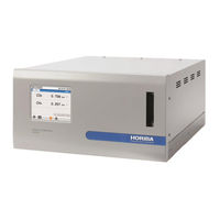
horiba GA-370 Instruction Manual (95 pages)
Trace Gas Monitor
Brand:
horiba
| Category:
Measuring Instruments
| Size: 6.97 MB
Table of Contents
Product Handling Information
8
Manual Information
10
Table of Contents
11
Figures
14
Overview
17
Introduction
17
Names and Functions of Parts
18
Front Panel
18
Fig. 1 Front Panel
18
Table 1 Names and Functions of Parts of Front Panel
18
Rear Panel
19
Fig. 2 Rear Panel
19
Table 2 Names and Functions of Parts of Rear Panel
19
Operation Screens
20
Fig. 3 Operation Screen (Measurement Value Display)
20
Table 3 Names and Functions of Buttons (Operation Screens)
20
Fig. 4 Function Buttons and Corresponding Screens
21
Table 4 Functions of Function Buttons
21
Screen Flow and Key Operations
22
Fig. 5 Screen Flow
22
Preparations
23
Contact for Installation
23
Installation Conditions
23
Cables
24
Fig. 6 Rear Panel Cable Connectors
24
Table 5 Cable Connector List
24
Tubing
25
Tube Connectors on Rear Panel
25
Fig. 7 Rear Panel Tube Connectors
25
Table 6 Tube Connector List
25
Connections
26
About Reference Gas
26
Fig. 8 Tube Connection Diagram
26
Table 7 Reference Gas List (Base Gas same as Sample Gas)
26
Analyzer Operation Preparations
27
Analyzer Startup
27
Fig. 9 Startup Screen
27
Locking and Unlocking the Keys
28
About the Key Lock
28
How to Change the Key Lock State
29
Fig. 10 KEY LOCK Setting Screen
29
Fig. 11 KEY UNLOCK Input Screen
29
Main Unit Settings
30
Table 8 Setting Items at Initial Startup
30
Operations
31
Operation Flow
31
Checking the Flow Rates
32
Checking the Sample Gas Flow Rate
32
Checking the Reference Gas Flow Rate
32
Calibration
33
Fig. 12 CALIBRATION MENU Screen
33
CALIBRATION Screen
34
Fig. 13 Various CALIBRATION Screens
34
Table 9 Various Names and Functions (CALIBRATION Screen)
35
Calibration Preparations
36
Fig. 14 CALIBRATION RANGE Screen
36
Fig. 15 Calibration Range Selection Screen
36
Fig. 16 SPAN GAS CONC. Screen
37
Fig. 17 Span Gas Concentration Value Input Screen
37
Switching Mode
38
Fig. 18 Mode Selection Screen
38
Table 10 Selection Items in Mode Selection Screen
38
Zero Calibration
39
Fig. 19 Example after Mode Selected (ZERO CALIBRATION Screen 1)
39
Fig. 20 Zero Calibration Screen 2 (Calibration Execution)
39
Span Calibration
40
Fig. 21 SPAN CALIBRATION Screen 2 (Calibration Execution)
40
Canceling Calibration Alarms
41
Fig. 22 CALIBRATION Screen 3 (When Calibration Alarm Occurrence)
41
Fig. 23 Confirmation Message (Calibration Alarm Clear)
41
Calibration Coefficient History Check
42
Fig. 24 DATA MENU Screen
42
Fig. 25 CAL. COEF. HISTORY Screen
42
Fig. 26 CAL COEF. HISTORY Screen of Selected Component
43
Table 11 Display Items of CAL COEF. HISTORY Screen
43
Ending Calibration
44
Fig. 27 CALIBRATION Screen (During Replacement)
44
Measurement
45
MEASUREMENT Screen
45
Fig. 28 MEASUREMENT Screen (Measurement Value and Graph Display)
45
Table 12 Various Names and Functions (MEASUREMENT Screen)
45
Measurement Operation
46
Fig. 29 MEASUREMENT Screen
46
Changing Display of MEASUREMENT Screen
47
Range Settings
47
Fig. 30 MEASUREMENT MENU Screen
47
Fig. 31 RANGE CHANGE Screen
47
Fig. 32 RANGE CHANGE Screen
48
Table 13 Selection Items in RANGE CHANGE Screen
48
Graph Scale Setting
49
Fig. 33 MEASUREMENT Screen (Graph Display)
49
Fig. 34 Horizontal Axis Scale Setting Screen
49
Event Check
50
Fig. 35 MEASUREMENT Screen (When Event Occurring)
50
Table 14 Classification of Events
50
Fig. 36 EVENTS Screen
51
Stopping the Analyzer
52
Fig. 37 SYSTEM SHUTDOWN Screen
52
Fig. 38 Confirmation Message Screen (System Shutdown)
52
Various Functions
53
MENU Screen
53
Fig. 39 MENU Screen
53
Table 15 Common Operations of MENU Screens
53
Calibration Menu
54
Fig. 40 CALIBRATION MENU Screen
54
Table 16 Menu Name List
54
Table 17 Setting Items of CALIBRATION MENU Screen
54
Measurement Menu
55
Data Menu
55
Fig. 41 MEASUREMENT MENU Screen
55
Fig. 42 DATA MENU Screen
55
Table 18 Setting Items of MEASUREMENT MENU Screen
55
Table 19 Setting Items of DATA MENU Screen
55
Periodic Replacement Parts Management
56
Fig. 43 PARTS MANAGEMENT Screen
56
Fig. 44 each PART MANAGEMENT Screen
57
Fig. 45 LIMIT TIME Setting Screen
57
Table 20 each PART MANAGEMENT Screen Display Items
57
Fig. 46 Reset Confirmation Screen (Example: PARTS MANAGEMENT Screen)
58
Analog Input Value Check
59
Fig. 47 ANALOG INPUT Screen
59
Analog Output Value Check
60
Fig. 48 ANALOG OUTPUT Screen
60
Calibration Coefficient History Check
61
Fig. 49 CAL COEF. HISTORY Screen (Component Selection)
61
Fig. 50 CAL COEF. HISTORY Screen of Selected Component
61
Table 21 Display Items of CAL. COEF. HISTORY Screen
61
Event History Check
62
Fig. 51 EVENT HISTORY Screen
62
Table 22 Event History Display Items
62
System Menu
63
Fig. 52 SYSTEM MENU Screen
63
Table 23 Setting Items of SYSTEM MENU Screen
63
Time and Date
64
Fig. 53 TIME and DATE Screen
64
Fig. 54 TIME and DATE Selection Screen
64
Table 24 Time and Date Setting Items
64
Fig. 55 DATE FORMAT Selection Screen
65
Table 25 Time and Date Setting Ranges
65
LCD Settings
66
Fig. 56 LCD Screen
66
Table 26 LCD Items
66
Fig. 57 DISPLAY off TIME Setting Screen
67
Table 27 Setting Items of DISPLAY off TIME
67
Touch Panel Adjustment
68
Fig. 58 TOUCH PANEL ADJUSTMENT Screen
68
Fig. 59 TOUCH PANEL ADJUSTMENT Screen (after Adjustment Completed)
68
Password Settings
69
Fig. 60 TOUCH PANEL ADJUSTMENT Screen (When Failed)
69
Fig. 61 PASSWORD Screen
69
Fig. 62 Current PASSWORD Input Screen
70
Fig. 63 New PASSWORD Input Screen
70
Fig. 64 New PASSWORD (Confirm) Input Screen
70
Analyzer Information Check
71
Fig. 65 Password Input Error Screen
71
Fig. 66 about ANALYZER Screen
71
Maintenance
72
Contact for Maintenance
72
Daily Checks
72
Replacement of Parts
73
How to Replace the Filters and Packing
73
Fig. 67 Rear Panel Filter Section
73
Troubleshooting
74
Before Troubleshooting
74
Failure Causes and Remedial Actions
74
No Sensitivity
74
Low Sensitivity
75
Noise and Reading Variations
75
Slow Response Speed
75
Significant Drift
76
Over Range Reading
76
Lower Output Signal Level
76
Higher Output Signal Level
77
Reading Unstable
77
Screen Not Displayed
77
Power Does Not Turn on
77
Settings Cannot be Changed
78
Remedial Actions When Events Occur
78
Types of Information and Remedial Actions
78
Table 28 Types of Information
78
Types of Alarms and Remedial Actions
79
Table 29 Types of Alarms and Remedial Actions
79
Types of Cautions and Remedial Actions
80
Table 30 Types of Cautions and Remedial Actions
80
External Input/ Output
81
Analog Signal Output (ANALOG out Connector)
81
Fig. 68 ANALOG out Connector
81
Table 31 ANALOG out Connector Pin Assignment (Analog Output)
81
Contact Output (DIGITAL out Connector)
82
Fig. 69 DIGITAL out Connector
82
Table 32 DIGITAL out Connector Pin Assignment (Contact Output)
82
Contact Input (DIGITAL in Connector)
84
Fig. 70 DIGITAL in Connector
84
Table 33 DIGITAL in Connector Pin Assignment (Contact Input)
84
Reference
85
Measuring Principles
85
Fig. 71 Configuration Diagram
86
Specifications
87
Replacement Parts List (Standard Accessories and Consumables)
88
Table 34 Replacement Periods of Consumables
88
Removing and Fixing the Fixtures for Transport
89
Related Diagrams
91
Advertisement
Advertisement
Related Products
horiba Yumizen G200
horiba Yumizen G400
horiba Yumizen G400 DDi
horiba Yumizen G405
horiba 1300047272
horiba 1300052253
horiba 1300077981
horiba 1300093769
horiba Categories
Measuring Instruments
Security Sensors
Test Equipment
Laboratory Equipment
Monitor
More horiba Manuals
Login
Sign In
OR
Sign in with Facebook
Sign in with Google
Upload manual
Upload from disk
Upload from URL