Sign In
Upload
Manuals
Brands
HORIBA ABX Manuals
Medical Equipment
PENTRA 80 RAA022B
User Manuals: HORIBA ABX PENTRA 80 RAA022B Autoloader
Manuals and User Guides for HORIBA ABX PENTRA 80 RAA022B Autoloader. We have
1
HORIBA ABX PENTRA 80 RAA022B Autoloader manual available for free PDF download: Technical Manual
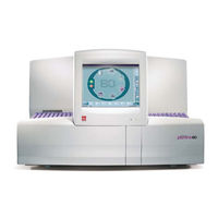
HORIBA ABX PENTRA 80 RAA022B Technical Manual (375 pages)
Large capacity autoloader (100 tubes)
Brand:
HORIBA ABX
| Category:
Medical Equipment
| Size: 19.37 MB
Table of Contents
Environment
3
Grounding
3
Location
3
Working Conditions
3
Table of Contents
5
Specifications
5
1 Technical Specifications
6
Parameters
6
Throughput Analyses
6
Tube Identification
6
Reagents
7
Internal Computer
7
Measurements and Computation
7
2 Physical Specifications
7
Power Requirements
7
Operating Temperature and Humidity
7
Dimension and Weight
7
Minimum Specimen Volume
8
Hgb Measurement
8
Counting Aperture Diameters
8
Reagent Consumption (Ml)
8
Dilution Ratios
8
3 Summary of Performance Data
9
Repeatability
9
Linearity
9
Carryover
9
4 Reagents Specification
10
Abx Diluent
10
Abx Lyse
10
Abx Biolyse
10
Abx Cleaner
11
Abx Eosinofix
11
Abx Basolyse II
11
Waste Handling Precautions
12
5 Limitations
12
Blood Specimens
12
Known Interfering Substances
12
Maintenance
12
Hydraulic & Pneumatic Principles
15
Hydropneumatic Connections
16
Instrument Tubing
19
Tube List
19
Connectors and Integrated Tubings List
21
Function of Valves
21
Hydraulic Circuit
22
Cleaner Circuit
23
Basolyse 2 Circuit
24
Eosinofix Circuit
25
Lyse Circuit
26
Diluent Circuit
27
Diluent Prime Circuit
28
Counting Circuit
29
LMNE Transfer Circuit
30
LMNE Injection Circuit
31
Pneumatic Diagram
32
Electric & Electronic Principles
35
Main Board General View
37
Motor Board General View
38
Connectors and Other Boards
38
CBC008A Barcode Reader
39
DAD075AS Flat Cable 350Mm. 14Pts
40
DAD107AS Flat Cable 480Mm. 14Pts
41
DAD109A Flat Cable 560Mm. 14Pts
42
DAD112AS Flat Cable 930Mm. 26Pts
43
DAD119AS Flat Cable 950Mm. 8Pts
44
DAD120A Flat Cable 800Mm. 14Pts
45
DAD121A Flat Cable 700Mm. 44Pts
46
DAD122A Flat Cable 650Mm. 14Pts
47
DAD123A DSUB 25Pts Flat Cable 1000Mm
48
DAD124A DSUB 9Pts Flat Cable 1000Mm
49
XAA428C Carriage Board
50
XAA429A Leds Board
51
XAA456A Main Board
52
XAA458A LMNE Amplifier Board
53
XAA459A Motor Board
54
XAA478A Solenoid Board
55
XBA322B External Waste Level Detection
56
XBA342A Infrared Sensor
57
XBA387A Reagent Heating Coil
58
XBA389A Hemoglobin Photometer
59
XBA393A Upper Fan
60
XBA396A Infrared 260Mm
61
XBA398B RBC&WBC Electrode Coaxial Cable
62
XBA399B LMNE Flowcell Coaxial Cable
63
XBA425A Chamber Heating
64
XBA427A Emergency Position Assy
65
XBA431A Infrared Photocell 600Mm. (no Tab)
66
XBA432A Infrared Photocell 600Mm. (2 Tabs)
67
XBA433A Infrared Photocell 600Mm. (1 Tab)
68
XBA458A Switch JST 300Mm
69
XBA459A Switch JST 400Mm
70
XBA460A Switch Jst 500Mm
71
XBA461A Switch Jst 700Mm
72
XBA462A Motor Jst 300Mm
73
XBA463A Motor Jst 400Mm
74
XBA464A Motor Jst 500Mm
75
XBA465A Motor Jst 700Mm
76
XBA469A Horizontal Carriage Cell Extension
77
XBA470A Solenoid JST 700Mm
78
XBA471A Solenoid Molex 230Mm
79
XBA478A Horizontal Carriage Motor
80
XBA486A Leds Extension JST 1000Mm
81
XBA487A LED JST 200Mm
82
XBA488A Waste Level Detection
83
XDA605A Diluent Reservoir with Level Detection
84
XDA751C 12 Valves Assy (LV1-6 & LV7-12)
85
XDA752C 7 Valves Assy (LV13-19)
86
XDA753C Carriage Valves Assy (LV20-23)
87
XDA754C 7 Valves Assy (LV24-30)
88
XDA755C 5 Valves Assy (LV31-35)
89
Pentra 80 Synoptic
89
Analysis Cycle Technology
91
Analysis Cycle Description
92
Measuring Principles
94
Multi Distribution Sytem (MDSS)
94
CBC Mode
94
Diff Mode
94
CBC Detection Principles
95
Rbc/Plt
95
RDW Calculation
96
Rbc\Plt Dilutions
96
MCV, MCH, MCHC Calculation
97
MPV Measurement
97
Pct Calculation
97
PDW Calculation
97
BASO/WBC Count
98
Wbc\Baso Count
98
LMNE Matrix
99
WBC Counts
99
Absorbance Measurement
100
Software Release
103
Service Software Overview
104
Super User Menu
104
Mechanical
104
Hydraulic
104
Miniclean
105
Concentrated Cleaning
105
Autoclean
105
Technician Menu
105
Windows Explorer Access
106
Gains
106
Others
106
Software Releases
106
Alarms & Error List
107
Analyzer Error Types and Help Messages
108
Transfer Error Types an Help Messages
109
STAT Mode Error Type and Help Messages
110
Environment Error Type and Help Messages
110
User Error Types and Help Messages
111
Expiration Date Error Types and Help Messages
111
Environment Error Types and Help Messages
111
Analyzer Internal Barcode Error Types and Help Messages
112
Maintenance
113
Daily Customer Maintenance
114
Maintenance Table
114
Introduction
114
Month Maintenance Kit
115
Yearly Maintenance Kit
115
Pistons Maintenance Kit
115
Fitting Kit
116
Screws Kit
116
Maintenance Procedures
116
Required Tools and Products
116
Procedures Chart Table
117
Training Department Procedure List
119
Transport and Installation
125
Lifting Handles Installation
125
Plastic Rails
125
Electrical & Computer Connections
126
Holding Plates
126
Computer’s Wiring
127
Reagents Installation
128
First Start of the Instrument
128
Racks
128
Check Keyboard Setup
129
Check Date\Time
129
Check Printer Configuration
129
Prime Reagents
129
Mechanic Check
130
Calibration
130
Control
130
Config. Save and Print
130
6 Month Maintenance
131
Rinsing Block
132
O'ring Replacement
132
Reagent Syringes
133
Draining & Counting Syringes
135
Instrument Cleaning
138
Concerned Assemblies
138
Filter
138
Yearly Maintenance Procedure
139
Yearly Maintenance Kit
140
Sampling Needle Replacement
140
Sampling Syringe O’ring Replacement
141
5DIFF Syringe O’ring Replacement
142
Optical Bench Lamp Replacement
143
LMNE Flowcell Coaxial Replacement
144
Optical Bench Lamp 6V Voltage Check
145
Diluent Reservoir Joint & Washer Replacement
146
Draining Chambers O’ring Replacement
147
Counting Heads RBC\WBC Coaxial Cable O’ring Replacement
148
Counting Head Aperture Joint Replacement
149
Tape on Trays
150
Check up after Intervention
150
Piston Kit Replacement Procedure
151
Piston & Needle Kit
152
Percutor (GBG169A) Replacement
152
Reagent Syringe Pistons Replacement
153
Draining Syringe 1 Piston Replacement
155
Draining Syringe 2 Piston Replacement
157
Counting Syringe Piston Replacement
157
Decontamination and Rinse Procedure
159
Manual Decontamination
160
Analysis Circuit Decontamination
160
Instrument Rinse
161
Chambers Adjustment Procedure
163
Alignment Check and Adjustment
164
Probe Adjustment Procedure
167
MDSS Adjustment Menu
168
Needle Adjustment
168
Needle Home Check
168
Needle Home Adjustment
169
Needle Position Check
169
Carriage Adjustment
171
Carriage Home Check & Adjustment
171
Needle Position Adjustment
171
Carriage Position Check
173
Carriage Positions Adjustment
173
Main Board Adjustment Procedure
177
How to Access Main Board
178
Main Board Check
180
Power Supply Check
180
High Voltage Supply Check
180
Main Board Adjustment
181
Hgb Blank Adjustment
181
Rbc\Plt Gain Adjustment
181
Wbc\Baso Gain Adjustment
182
Liquid Sensors Adjustment
182
Motor Current Adjustment
183
Threshold Adjustment
183
Motor Current
183
Motor Board Adjustment Procedure
185
How to Access to the Motor Board
186
Motor Board Check and Adjustment
188
Temperature Adjustment Procedure
189
Reagent Heating Coil Check & Adjustment
190
Reagent Heating Coil Temperature Check
190
Reagent Heating Coil Temperature Adjustment
191
Thermostatic Compartment Temperature Check
191
Thermostatic Compartment Temperature Adjustment
192
Vacuum Adjustment Procedure
195
Draining Syringe Vacuum Check (no Adjustment Available)
196
Counting Syringe Vacuum Check and Adjustment
198
Counting Syringe Vacuum Adjustment
199
Bubbling Adjustment Procedure
201
LMNE Flowcell Adjustment Procedure
203
LMNE Flowcell Adjustment Check
204
Clean Cycle
205
LMNE Adjustment
205
Sample the Latex
206
LMNE Adjustment Screen
206
Target Values
206
LMNE Flowcell Position Adjustment
207
Mother Board
208
Optical Bench Adjustment
208
LMNE Balance Adjustment Procedure
211
LMNE Menu
212
Stat Mode Button
212
Fresh Blood Tube
212
Old Coef
213
Auto Calibration Screen
213
New Coef
214
Calibration Coefficients
214
Tube Holder Adjustment Procedure
215
Tube Holder General View
216
Tube Holder Assembly Replacement
216
Tube Holder Dimantling
217
Tube Holder Pre-Adjustment
217
Tube Holder Adjsutments
218
Tube Holder Centering Check
218
Tube Holder Centering Adjsutment
218
Tube Holder Play Adjustment
219
Tube Holder Locker
219
Opening Speed Adjustment
220
Adjustment Check
220
Compatible Tube List
221
Compatible Tube List for Rack
224
Power Supply Replacement Procedure
225
Power Supply Front Screws
227
Power Supply Back Screws
227
Power Supply Voltages
227
Test Points
228
Check up after Intervention Procedure
229
Optical Bench Dismantling & Replacement Procedure
233
Optical Bench Dismantling
234
LMNE Syringe and Valves Disconnection
234
Optical Bench Lamp Disconnection
235
Optical Bench Electronic Board Dismantling
235
Optical Bench Fixation Screws
235
Control of the Optical Bench
236
Emission Gun Control of Position
236
Optical Bench Cover Dismantling
236
Front Panel & Covers Dismantling Procedure
239
Front Left Cover
240
Front Right Cover
240
Right Door
241
Right Side Cover
241
Reagent Cover
242
Left Side Cover
242
Left Panel
243
Loading Tray
243
Rear Panel
244
Bottle Support
244
Motor Board Protection
245
Ejection Tray
246
Upper Cover
246
Internal Barcode Adjustment Procedure
247
Barcode Reader Adjustment Check
248
Barcode Screen
248
Barcode Reader Adjustment
249
Barcode Configuration
250
Typology and Ckeck Digit
250
Settings Parameters Meaning
251
Troubleshooting
251
Labels Are Never Read
251
Labels Are Read, but an Added Digit Appears on the Right Side
251
External Barcode Configuration Procedure
253
Barcode Reader Configuration Check
254
INTERLEAVED 2 of 5 (no «Check Digit» Control)
254
CODE 39 (no «Check Digit» Control)
254
CODE 128 (Control Without «Check Digit» Transmission)
254
Barcode Reader Setup
255
Heater Assy Replacement Procedure
257
Heater Assy Dismantling
258
Thermostatic Room Dismantling
258
Chamber Assembly Dismantling
258
Heater Replacement
259
Heater Disconnection
259
CTN Disconnection
259
Mixer Replacement Procedure
261
Mixer Assembly Dismantling
262
Top Sampler Transfer Rail Dismantling
262
Reagent Syringe Dismantling
262
Plastic Protection
263
Mixer Disconnection
263
Mixer Assembly Replacement
263
Mixer Location
263
Technical Adjustment Screen
264
Vertical Position
265
Horizontal Position
265
Automatic Sampler
267
Loading Mechanism Check & Adjustment
268
Max Rack Loading
268
Stop Rack Loading
269
Max Rack Loading Gap
269
Rack and Front Plate Play
269
Mixer Mechanism Check & Adjustment
270
Transfer Mechanism Check & Adjustment
270
Transfer Home
270
Stop Transfer
271
Carriage Position
271
Rack Ejection
272
End of Transfer
272
First Transfer
273
Internal PC Replacement Procedure
275
PC Dismantling
276
PC Disconnection
276
LED Connector
277
Righthand Side PC Fixation Screws
277
PC Installation
278
Lefthand Side PC Fixation Screws
278
PC Hard Disk Replacement Procedure
279
Cover Plate + Fan
280
Hd Assy Screws
280
Flat Cable Disconnection
281
Floppy Disk Reader Connection
281
Drives Support
282
Hard Disk Screws
282
Hard Disk
282
Hard Disk Connector
283
PC Mother Board Replacement Procedure
285
TFT Board
288
FPC Flat Cable Connection
289
SDRAM Disconnection
289
PC Floppy Disk Reader Replacement Procedure
291
PC CD-ROM Drive Replacement Procedure
295
CD-ROM Board
299
PC Touch Screen Replacement Procedure
301
Touch Screen Dismantling
302
Touch Screen Interface Board
302
Touch Screen Connection
302
New Touch Screen Installation
303
Interface Board Connection
303
For a Pentra 80
304
For a Pentra XL80
304
Instrument Mother Board Replacement Procedure
305
Mother Board Access
306
Mother Board Dismantling
306
Mother Board Replacement
307
Main Board Connections
307
Motor Board Replacement Procedure
309
How to Access to Motor Board
310
Motor Board Dismantling
310
Motor Board Replacement
310
Sensors Check and Adjustment Procedure
311
Sensor Check
312
Loading Area
312
Stop Rack Loading Sensor Right
312
Sampler Transfer Rail
313
Tube Sensor
313
Left Rack Locker / Right Rack Locker
313
Unloading Area
314
Rack End Transfer
314
Unloading Area Full
314
Covers
315
Waste
315
Front Cover
315
Thermic Panel
315
Sensors Adjustment
316
Stop Rack Loading Sensors Adjustment
316
Switch Wheel Position
316
Tube Holder Cam
320
Home Loader Switch
320
Save and Restore Settings
321
Analyser Setting
322
Analyser Setting Save
322
Analyser Setting Restore
323
Workstation Setting
323
Print
324
Print Analyzer Settings
324
Print Settings
324
Print both
324
Exploded Views
325
Spare Part List
370
Advertisement
Advertisement
Related Products
HORIBA ABX PENTRA 80 RAA022AA
HORIBA ABX Categories
Laboratory Equipment
Medical Equipment
More HORIBA ABX Manuals
Login
Sign In
OR
Sign in with Facebook
Sign in with Google
Upload manual
Upload from disk
Upload from URL