Sign In
Upload
Manuals
Brands
Honeywell Manuals
Transmitter
STT750 SmartLine
Honeywell STT750 SmartLine Manuals
Manuals and User Guides for Honeywell STT750 SmartLine. We have
4
Honeywell STT750 SmartLine manuals available for free PDF download: User Manual, Quick Start Installation Manual, Quick Start Manual
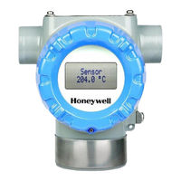
Honeywell STT750 SmartLine User Manual (72 pages)
Temperature Transmitter
Brand:
Honeywell
| Category:
Transmitter
| Size: 3.57 MB
Table of Contents
Table of Contents
7
1 Introduction
11
Overview
11
Features and Options
11
Physical Characteristics
11
Table 1 - Features and Options
11
Functional Characteristics
12
Figure 1 - STT750 Major Assemblies
12
Figure 2 - Electronics Housing Components
12
STT750 Smartline Transmitter Nameplate
13
Safety Certification Information
13
Transmitter Adjustments
13
Figure 3 -Typical STT750 Nameplate
13
Display
14
Optional 3-Button Assembly
14
Table 2 - Available Display Characteristics
14
Revision
14
2 Application Design
15
Overview
15
Safety
15
Accuracy
15
Diagnostic Messages
15
Table 3 - STT750 Standard Critical Diagnostics Messages
16
Table 4 - STT750 Standard Non-Critical Diagnostics Messages
16
3 Installation and Startup
17
Installation Site Evaluation
17
Honeywell MC Toolkit
17
Display Installation Precautions
17
Mounting STT750 Smartline Temperature Transmitters
18
Summary
18
Figure 4 - STT750 with Adapter Housing - Horizontal Wall Mounting
18
Figure 5 - STT750 No-Adapter Horizontal Wall Mounting
18
Figure 6 - STT750 Pipe Mount with Adapter Housing - Horizontal & Vertical
19
Figure 7 - STT750 Pipe Mount, Vertical
19
Mounting Dimensions
20
Figure 8 - STT750 with Adapter Housing - Dimensions
20
Figure 9 - STT750 no Adapter Housing Dimensions
21
Bracket Mounting Procedure
22
Figure 10 - Pipe Mounting Bracket Secured to a Horizontal or Vertical Flat Pipe and Angle Pipe
22
Wiring a Transmitter
23
Loop Power Overview
23
Figure 11 - HART/DE Transmitter Operating Ranges
23
Figure 12 - Transmitter 9-Screw Terminal Board and Grounding Screw
24
Wiring Variations
25
Loop Wiring Procedure
25
Grounding and Lightning Protection
26
Explosion-Proof Conduit Seal
26
Input Sensor Wiring
27
Figure 13 - STT750 Thermocouple, RTD, MV, Ohm and Volt Connections
27
Startup
28
Overview
28
Startup Tasks
28
Output Check Procedures
28
Constant Current Source Mode Procedure
29
Figure 14 - Current Loop Test Connections
29
4 Operation
30
Overview
30
Three-Button Operation
30
Figure 15 - Three-Button Option
30
Data Entry
31
Menu Navigation
31
Table 5 - Three-Button Option Functions
31
Editing a Numeric Value
32
Selecting a New Setting from a List of Choices
32
Table 6 - Three-Button Data Entry
32
Table 7 - the Display Menus
33
The Display Menu
33
Three Button Operation with no Display Installed
37
Zero Adjustment
37
Span Adjustment
37
Changing the Default Failsafe Direction
38
Procedure to Establish Failsafe Operation
38
Figure 16 - Locating the Failsafe and Write Protect Jumpers
38
Table 8 - HART Failsafe and Write Protect Jumpers
39
Monitoring the Display
40
Display
40
Figure 17 - Display with Process Variable Format
40
5 Maintenance
41
Overview
41
Preventive Maintenance Practices and Schedules
41
Replacing the Communication Module
41
Figure 18 - PWA Replacement
41
6 Calibration
44
Recommendations for Transmitter Calibration
44
Calibration Procedures
44
7 Troubleshooting
45
Overview
45
Critical Diagnostics Screens
45
Fault Conditions and Recommended Corrective Actions
45
Table 9 - Fault Conditions and Recommended Corrective Actions
45
8 Parts List
46
Overview
46
Table 10 - Summary List of Recommended Spare Parts
46
Figure 19 - Pipe and Wall Bracket Parts
47
Figure 20 - Electronic Housing, Display End
48
Table 11 - Pipe and Wall Bracket Parts
48
Table 12 - Transmitter Major Assemblies
48
Figure 21 - Electronic Housing, Terminal Block End
49
Appendix A. PRODUCT CERTIFICATIONS
50
Warnings and Cautions
59
9 Appendix B - Security
67
How to Report Security Vulnerability
67
Glossary
68
Advertisement
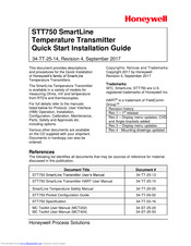
Honeywell STT750 SmartLine Quick Start Installation Manual (20 pages)
SmartLine Temperature Transmitter
Brand:
Honeywell
| Category:
Transmitter
| Size: 1.24 MB
Table of Contents
Table of Contents
2
Installation
3
Features and Options
3
Figure 1 - Electronics Housing Components
3
Mounting the Transmitter
4
Figure 2 - STT750 with Adapter Housing - Horizontal Wall Mounting
4
Figure 3 - STT750 Pipe Mount, Vertical
4
Bracket Mounting
5
Figure 4 - STT750 Pipe Mount with Adapter Housing - Horizontal & Vertical
5
Optional Mounting Bracket
6
Figure 5: Flat and Angle Mounting Brackets Secured to Horizontal or Vertical Pipe
7
Conduit Entry Plugs and Adapters
8
Figure 6: Electronic Housing Conduit Entries
8
Wiring Connections and Power up
9
Figure 7 STT750 HART/DE Transmitter Operating Ranges
9
Figure 8: Transmitter 9-Screw Terminal Board and Grounding Screw
10
Figure 9 - STT750 Thermocouple, RTD, MV, Ohm and Volt Connections
11
Input Sensor Wiring
11
Wiring Variations
11
Explosion-Proof Conduit Seal
12
Set the Jumpers for HART
13
Setting Failsafe Direction and Write Protect Jumpers
13
Table 1 - Jumper Settings
14
Figure 10: Jumper Location HART
14
Configuration Guide
15
Table 2 - Available Display Characteristics
15
Table 3 - Basic Display Configuration
15
Honeywell STT750 SmartLine Quick Start Manual (11 pages)
Temperature Transmitter
Brand:
Honeywell
| Category:
Transmitter
| Size: 1.88 MB
Table of Contents
Table of Contents
1
Url
1
Note
1
Installation
1
Features and Options
1
Mounting the Transmitter
1
Bracket Mounting
2
Optional Mounting Bracket
2
Conduit Entry Plugs and Adapters
2
Wiring Connections and Power up
2
Wiring Variations
3
Note: after Wiring, Torque the Screws to Around 4 to 5(Lb-In). Maximum Should Not Exceed 1.1 Nm (10 Lb-In). Don't Pull the Wires after Connecting to the Screw Terminals
3
Input Sensor Wiring
3
Digital Output Wiring
4
Setting Failsafe Direction and Write Protect Jumpers
4
Write Protect Jumper on Foundation Fieldbus (FF)
5
Advertisement
Honeywell STT750 SmartLine Quick Start Manual (8 pages)
Brand:
Honeywell
| Category:
Transmitter
| Size: 1.56 MB
Table of Contents
Table of Contents
1
Url
1
Note
1
Installation
1
Features and Options
1
Mounting the Transmitter
1
Figures Figure 1 - Electronics Housing Components
1
Bracket Mounting
2
Optional Mounting Bracket
2
Conduit Entry Plugs and Adapters
2
Wiring Connections and Power up
2
Wiring Variations
3
Input Sensor Wiring
3
Digital Output Wiring
4
Setting Failsafe Direction and Write Protect Jumpers
4
Write Protect Jumper on Foundation Fieldbus (FF)
5
Advertisement
Related Products
Honeywell STT850 SMARTLINE
Honeywell STT25D
Honeywell STT25H
Honeywell STT25M
Honeywell STT850 Series
honeywell STT700 SmartLine
Honeywell SmartLine STT700 DE
Honeywell STT700 STT700
Honeywell STGW73L
Honeywell STFW132
Honeywell Categories
Thermostat
Controller
Control Unit
Security Camera
Accessories
More Honeywell Manuals
Login
Sign In
OR
Sign in with Facebook
Sign in with Google
Upload manual
Upload from disk
Upload from URL