Sign In
Upload
Manuals
Brands
Honeywell Manuals
Receiver
MX8000
Honeywell MX8000 Manuals
Manuals and User Guides for Honeywell MX8000. We have
1
Honeywell MX8000 manual available for free PDF download: Installation And Operation Manual
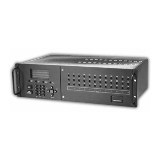
Honeywell MX8000 Installation And Operation Manual (192 pages)
Digital Alarm Receiver
Brand:
Honeywell
| Category:
Receiver
| Size: 1.9 MB
Table of Contents
Table of Contents
2
Section 1 System Overview
9
Features
9
Optional Accessories
9
Formats Compatible with the MX8000
10
Table 1-1: Optional Accessories for the MX8000 Receiver
10
Table 1-2: Formats Compatible with the MX8000
10
MX8000 Supported SIA Digital I-III Levels
11
How to Use this Manual
11
Table 1-3: MX8000 and SIA Levels I-III Comparison
11
Terminology
12
What's in the Box
12
General Recommendations, Notes, and Limitations
13
How to Contact Technical Support
16
Section 2 Agency Requirements
17
Telephone Requirements
17
FCC Statement
17
Industry Canada Statements
17
UL Requirements
18
Hardware Requirements
18
Operational Requirements
19
Programming Requirements
19
Section 3 Installation
21
Quick Start
21
Environmental Specifications
21
Electrical Specifications
21
Overview
22
Figure 3-1: MX8000 Front View
22
Figure 3-2: MX8000 Front View Without Front Plate Attached
22
Figure 3-3: MX8000 Rear View
22
Rack Mounting
23
Figure 3-4: Rack Mount Enclosure, Front View
23
Hot Swapping of Line Cards
24
Figure 3-5: Rack Mount Enclosure, Rear View
24
Line Card Installation
25
Figure 3-6: Line Card Locations
25
Figure 3-7: Line Card Position and Components
26
Removing Line Cards
27
Telephone Line Connection
27
3.10 Parallel Printer Connection
27
3.10.1 Printer Cable Pin-Outs
28
Table 3-1: External Printer Cable Pin Description
28
Figure 3-8: Parallel Printer Cable Connection to MX8000
28
Figure 3-9: Wiring Sequence for Parallel Printer Port Interface
28
Com Ports 1 and 2
29
3.10.3 Remote Alert Output
29
3.11 AC Power Cord Connection
29
3.11.1 Switching to a 240 VAC Power Supply
29
Figure 3-10: MX8000 Remote Alert Output/Backup Battery Connection
29
3.11.2 How to Verify Earth Ground
30
Figure 3-11: CPU, PS, User Interface Assembly Retaining Screw Locations
30
Figure 3-12: Side View of CPU, PS, User Interface Assembly
30
3.12 Battery Connection
31
Figure 3-13: Outlet Voltage Measurement Points
31
Figure 3-14: Battery Connections
31
3.13 Automation Computer Connection
32
3.13.1 Computer Port Baud Rate Selection
32
3.14 Master/Slave Receiver Linking
32
3.14.1 Receiver Linking Cabling Connections
32
Figure 3-15: 25-Pin Null Modem Cable Connection
32
Figure 3-16: 9-Pin Null Modem Cable Connection
32
3.14.2 Master/Slave Linking Programming
33
Figure 3-17: MX8000 Master/Slave Receiver Linking Cabling Connections
33
Figure 3-18: SBUS Receiver Linking Cable
34
Section 4 Operation
37
Touchpad Function Buttons
37
Figure 4-1: MX8000 Front Panel
37
Figure 4-2: Touchpad Layout
37
Displays
38
Table 4-1: Touchpad Buttons Description
38
LED Displays
39
VFD Status Display
39
Table 4-2: LED Description
39
Figure 4-3: VFD Display
39
Initial System Power up
40
Table 4-3: VFD and Printer Abbreviations
40
Figure 4-4: Power-Up Routine
40
Log on / Log off
41
Installer Profile
41
Operator Profile
41
Default User Codes
41
How to Log on the System
41
Table 4-4: Main Menu Option Items by Profile
41
Table 4-5: Default User Codes
41
How to Log off the System
42
Modes of Operation
42
Normal Mode
42
Program Mode
43
Main Menu
43
How to Display the Main Menu
43
Figure 4-5: Main Menu Display
43
How to Maneuver through Main Menu
44
Call History
44
Figure 4-6: Main Menu Controls
44
Figure 4-7: View of a Call History Screen
44
System History
45
System Info
45
Set Time & Date
45
Figure 4-8: System History Display Sequence
45
Figure 4-9: System Information Display
45
System Restart
46
Figure 4-10: Setting Time and Date Program Sequence
46
Figure 4-11: System Restart Display
46
Printer Menu
47
Table 4-6: Printer Menu Choices
47
Figure 4-12: Print Menu Items
47
Figure 4-13: Print Report Menu Items
48
Figure 4-14: Call History Options
48
Figure 4-15: System Configuration Print Items
49
Table 4-7: Event Format Choices and Meaning
50
Figure 4-16: Event Format Menu Items
50
Configure Printer
51
Program Menu
52
4.6.10 Diagnostics Menu
52
Table 4-8: Phantom Signals Formats List
52
Figure 4-17: Program Menu Items
52
Figure 4-18: Diagnostics Menu Items
52
Figure 4-19: Message Queue Level
53
Figure 4-20: Event Log Display
53
Figure 4-21: Diagnostic Formats
53
Figure 4-22: Select LC Debug Mode by Line Card
53
Figure 4-23: Line Statistics Display
54
Figure 4-24: Port Status View of Serial Port
54
Figure 4-25: Parallel Port Status View
54
Listen-In and Hang up
55
Extend Manual (Common) Listen-In Operation
55
Table 4-9: Abbreviation Display Character Meanings/High Low Status
55
PBX Operation
56
Testing the System
56
Figure 4-26: Phone Connector Pin-Out and Listen-In Wiring Diagram
56
Section 5 Programming
57
UL 864 Programming Requirements
57
How to Enter Program Mode
57
Programming Fields
57
Table 5-1: Types of Programming Fields
57
How to Maneuver Around in Program Mode
58
Programming Choices
58
General Options
58
Figure 5-1: Programming Controls
58
Figure 5-2: Program Menu Choices
58
Figure 5-3: General Options Display
58
Table 5-2: General Options Items and Description
59
Operation Mode
62
Table 5-3: Operation Mode Choices and Descriptions
62
Figure 5-4: Normal Operating Mode Display Indicating Manual Operation
62
Display Options
63
Table 5-4: Display Options and Descriptions
63
Figure 5-5: View of Display Options
63
How to Change Language Display
64
Communications
68
Table 5-5: Communications Options and Description
68
Figure 5-6: Communications Options Menu
68
Figure 5-7: Initialization String Display
72
Table 5-6: Initialization String Characters
73
Table 5-7: ITI Automation Format Options
76
Table 5-8: On-Board Annunciator and Auxiliary Relay Options
77
System Options
78
Table 5-9: System Options
78
Figure 5-8: System Options Display
78
Table 5-10: 685, CAPS, and CP-220 1-9/A-Z Entries
79
Message Queue Options
81
Figure 5-9: Message Queue Display
81
Slave List
82
Figure 5-10: Slave List Display
82
Virtual Receiver/Line Numbers
83
Figure 5-11: Virtual Receiver/Line Numbers Display
83
View Slave
83
Line Device Menu
84
Figure 5-12: Choosing Line Device Menu and Line Device Program Menu Items
84
Table 5-11: Line Device Menu Options
85
Add Line Device
94
Edit Line - MX8000-LC3 (3 Line)
94
Table 5-12: MX8000-LC3 Edit Line List Items and Description
95
Figure 5-13: MX8000-LC3 Handshake Sequence Menu
95
Figure 5-14: MX8000-LC3 Handshake Order Number
95
Figure 5-15: MX8000-LC3 Line Options Menu
98
Table 5-13: Valid Programmable String Characters
100
Figure 5-16: MX8000-LC3 Listen Mode Menu Display
100
Table 5-14: Account Characters
101
Figure 5-17: MX8000-LC3 Listen in Accounts Menu
101
Figure 5-18: MX8000-LC3 Miscellaneous Phone Line Options
102
Figure 5-19: MX8000-LC3 Ring Options
104
Figure 5-20: MX8000-LC3 ADEMCO Auto Output Options
105
Figure 5-21: MX8000-LC3 Line Gain Options
107
Edit Line - MX8000-LRR
109
Figure 5-22: MX8000-LRR Line Edit
110
Table 5-15: Hexadecimal Alarmnet Number to Decimal Conversion
111
Edit Line - MX8000-LC1 (1 Line)
112
Table 5-16: MX8000-LC1 Edit Line List Items and Description
112
Figure 5-23: MX8000-LC1 Handshake Sequence Menu
113
Figure 5-24: MX8000-LC1 Handshake Order Number
113
Figure 5-25: MX8000-LC1 Line Options Menu
116
Figure 5-26: MX8000-LC1 Listen Mode Menu Display
118
Figure 5-27: MX8000-LC1 Listen in Accounts Menu
120
Figure 5-28: MX8000-LC1 Miscellaneous Phone Line Options
121
Figure 5-29: MX8000-LC1 ADEMCO Auto Output Options
123
Copy Device(S)
124
Clear Device
126
View Devices
126
Figure 5-30: Visual Steps to Clear a Line from the Receiver
126
User List
127
Adding a User
127
Table 5-17: User List Menu Items and Steps
127
Figure 5-31: User List Menu Items
127
Editing a User
128
Table 5-18: Available Characters
128
Clearing a User out of the Receiver
129
Section 6 Compatible Reporting Formats
131
Formats by Communication Group
131
Table 6-1: Formats Compatible with the MX8000
131
Format Numbers Used in Printer Output
133
Table 6-2: Formats by Report Number
133
Section 7 Troubleshooting
135
Error Messages
135
Table 7-1: Error Messages
135
Unrecognized Reports
138
Troubleshooting Process
138
Removing the CPU, PS, User Interface Assembly
139
Replacing the CPU, PS, User Interface Assembly
139
Safe Mode
139
Figure 7-1: User CPU, PS, User Interface Assembly Retaining Screw Locations
139
Section 8 Automation Communication Formats
141
Introduction
141
Conventions Observed in this Section
141
MX8000 Automation Protocols
141
Table 8-1: Automation Protocol Listing
141
Reporting Formats and Automation Protocol Support
142
Table 8-2: Reporting Formats and Automation Protocol Support
142
Ademco 8000
143
AE Header Block
143
Call Message Block
143
Table 8-3: AE Header Block Components Description
143
Table 8-4: Call Message Components and Description
143
Table 8-5: Dialer Format Types by Code
144
Table 8-6: Panel Data Identifiers and Descriptions
144
Table 8-7: Call Message Components
145
Table 8-8: Call Message with Listen-In Data
146
System Message Block
147
Table 8-9: Bad Data Field Indicator Components
147
Table 8-10: System Message Components
147
Heart Beat Message Block
148
Table 8-11: System Messages
148
Validation Byte (V-Byte)
149
Acking and Nacking Data
149
Commands Initiated by the Automation Computer
149
Table 8-12: Link Test Components
149
Table 8-13: Response Messages by the MX8000 Receiver
150
Table 8-14: Command Requests by Identifiers
150
Table 8-15: Log-In Request Components
150
Table 8-16: Log-Off Request Components
151
Table 8-17: Force Hang-Up Request Components
151
Table 8-18: Add Listen-In Account Request Components
151
Table 8-19: Delete a Listen-In Account Request Components
151
Table 8-20: Extend Listen-In Period Request Components
152
Table 8-21: End Listen-In Period Request Components
152
Table 8-22: Delete a Listen-In Account Request Components
152
ADEMCO 685 Automation Protocol
153
Link Test Request
153
Low Speed 3X1, 4X1, and 4X1 Express Automation Protocols
153
Low Speed 4X2 and 4X2 Express Automation Protocols
153
ADEMCO High Speed Automation Protocols
153
Figure 8-1: 685 3X1, 4X1, 4X1 Express Protocol
153
Figure 8-2: 685 4X2 and 4X2 Express Protocol
153
685 Contact ID
154
Figure 8-3: 685 ADEMCO High Speed Protocol
154
Figure 8-4: 685 Contact ID Protocol
154
Table 8-23: Contact ID Event Definition Codes
155
MX8000/685 System Messages
160
CAPS Automation Protocol
160
Figure 8-5: CAPS 4X2 and 4X2 Express Protocol
160
Table 8-24: MX8000/685 System Messages
161
FBII CP-220 Automation Protocol
162
3X1, 4X1, and 4X2 Automation Protocols
162
Acron 11 Digit with Zero or Space
162
FBII Superfast
162
Contact ID
162
Figure 8-6: CP-220 3X1, 4X1, 4X2 Protocol
162
Figure 8-7: CP-220 Acron 11 Digit Protocol
162
Figure 8-8: CP-220 FBII Superfast Protocol
162
CP-220/Silent Knight
163
Figure 8-9: CP-220 Contact ID Protocol
163
Figure 8-10: CP-220/Silent Knight Format 0
163
Figure 8-11: CP-220/Silent Knight Format 1 (FSK 1)
163
MX8000/CP-220 System Messages
164
Table 8-25: MX8000/CP-220 System Messages
164
Figure 8-12: CP-220/Silent Knight Format 6 (FSK 2)
164
SK9000 Protocol
165
Data String Description and Special Characters
165
Table 8-26: Data String Description
165
Table 8-27: Special Characters Used in the Protocol
165
Calls from Panels
166
Long Calls
166
Figure 8-13: SK9000 Example Message
166
Bad Data
167
Good Data with Bad Data
167
Validation Byte (V-Byte)
167
Figure 8-14: Long Event Data
167
System Messages
168
Communication from a Computer to the MX8000
168
Table 8-28: System Messages
168
Figure 8–15: System Message
168
ITI Generic Computer Format
169
Convention Used in this Section
169
Report Record
169
Table 8-29: Number and ITI Digit Equivalent
169
Table 8-30: Report Record Components
169
Table 8-31: Upper Nibble Description
170
Table 8-32: Lower Nibble Description
170
Table 8-33: Extended Panel ID Codes (XID)
170
Log Record
171
Table 8-34: Alarm Code and Description
171
Table 8-35: Log Record Components and Description
171
Test Record
172
OKAY Record
172
Acking and Nacking Data
172
8.10 ITI Computer Interface Format
172
8.10.1 Convention Used in this Section
172
Table 8-36: Test Record Components and Description
172
Table 8-37: Okay Record Components and Description
172
8.10.2 General Record Structure
173
8.10.3 Report Record
173
Table 8-38: Number and ITI Digit Equivalent
173
Table 8-39: Type of Record Identifiers
173
Table 8-40: Record Components
173
Table 8-41: Report Record Components and Description
174
Table 8-42: Information Field Identifiers
174
Table 8-43: Panel Type Characters
175
8.10.4 Test Record
176
Table 8-44: Condition Codes and Descriptions
176
Table 8-45: Test Record Information Fields and Descriptions
176
8.10.5 Supervisory Record
177
8.10.6 Log Records
177
8.10.7 Checksum/Control Field
177
Table 8-46: Log Record Information Fields and Descriptions
177
8.11 US ASCII Character Code
178
Table 8-47: Checksum Verification Process
178
Table 8-48: US ASCII Character Code
178
Appendix A Programming Quick Chart
179
Table A-1: Programming Quick Chart
179
Appendix B Receiver Update Procedure
187
Appendix C Index
189
Limited Warranty
191
Advertisement
Advertisement
Related Products
Honeywell MX8
Honeywell MX7 Tecton
Honeywell MX9
Honeywell MX3PLUS
Honeywell Solaris MS7820
Honeywell MN10 Series
Honeywell MN13CHESWW
Honeywell MN series IM
Honeywell MVN713A0000
Honeywell Modutrol IV M6285A4009
Honeywell Categories
Thermostat
Controller
Control Unit
Security Camera
Accessories
More Honeywell Manuals
Login
Sign In
OR
Sign in with Facebook
Sign in with Google
Upload manual
Upload from disk
Upload from URL